ASRock ALiveNF5-VSTA User Manual
ASRock ALiveNF5-VSTA Manual
 |
View all ASRock ALiveNF5-VSTA manuals
Add to My Manuals
Save this manual to your list of manuals |
ASRock ALiveNF5-VSTA manual content summary:
- ASRock ALiveNF5-VSTA | User Manual - Page 1
ALiveNF5-VSTA User Manual Version 1.0 Published January 2007 Copyright©2007 ASRock INC. All rights reserved. 1 - ASRock ALiveNF5-VSTA | User Manual - Page 2
any form or by any means, except duplication of documentation by the purchaser for backup purpose, without written consent of ASRock Inc. Products and corporate names appearing in this manual may or may not be registered trademarks or copyrights of their respective companies, and are used only for - ASRock ALiveNF5-VSTA | User Manual - Page 3
24 2.10 Hot Plug and Hot Swap Functions for SATA / SATAII HDDs .... 24 2.11 Driver Installation Guide 24 2.12 Installing Windows® 2000 / XP / XP 64-bit / VistaTM / VistaTM 64-bit Without RAID Functions 25 2.12.1 Installing Windows® 2000 / XP / XP 64-bit Without RAID Functions 25 2.12.2 Installing - ASRock ALiveNF5-VSTA | User Manual - Page 4
3.3 Advanced Screen 32 3.3.1 CPU Configuration 32 3.3.2 Chipset Configuration 35 3.3.3 ACPI Configuration 36 3.3.4 IDE Screen 45 4 . Software Support 46 4.1 Install Operating System 46 4.2 Support CD Information 46 4.2.1 Running Support CD 46 4.2.2 Drivers Menu 46 4.2.3 Utilities Menu - ASRock ALiveNF5-VSTA | User Manual - Page 5
cards and CPU support lists on ASRock website as well. ASRock website http://www.asrock.com 1.1 Package Contents 1 x ASRock ALiveNF5-VSTA Motherboard (ATX Form Factor: 12.0-in x 7.6-in, 30.5 cm x 19.3 cm) 1 x ASRock ALiveNF5-VSTA Quick Installation Guide 1 x ASRock ALiveNF5-VSTA Support CD 1 x Ultra - ASRock ALiveNF5-VSTA | User Manual - Page 6
Technology (see CAUTION 3) - 4 x DDRII DIMM slots - Support DDRII800/667/533 - Max. capacity: 8GB (see CAUTION 4) - CPU Frequency Stepless Control (see CAUTION 5) - ASRock U-COP (see CAUTION 6) - Boot Failure Guard (B.F.G.) - ASRock AM2 Boost: ASRock Patented Technology to boost memory performance - ASRock ALiveNF5-VSTA | User Manual - Page 7
CAUTION 10) - 4Mb AMI BIOS - AMI Legal BIOS - Supports "Plug and Play" - ACPI 1.1 Compliance Wake Up Events - Supports jumperfree - SMBIOS 2.3.1 Support - Drivers, Utilities, AntiVirus Software (Trial Version) - CPU Internal Temperature Sensing - CPU Ambient Temperature Sensing - Chassis Temperature - ASRock ALiveNF5-VSTA | User Manual - Page 8
when you install the PC system. 7. This motherboard supports ASRock AM2 Boost overclocking technology. If you enable this function in the BIOS setup, the memory performance will improve up to 12.5%, but the effect still depends on the AM2 CPU you adopt. Enabling this function will overclock the - ASRock ALiveNF5-VSTA | User Manual - Page 9
and users who purchase this motherboard and plan to submit Windows® VistaTM Premium and Basic logo, please follow the below table for minimum hardware requirement. CPU Memory VGA Sempron 2800+ 512MB Single Channel DX9.0 with WDDM Driver with 128bit VGA memory (Premium) with 64bit VGA memory (Basic - ASRock ALiveNF5-VSTA | User Manual - Page 10
module) DDRII_1 (64/72 bit, 240F-pSinBm8o0d0ule) FSB1GHz PARALLEL PORT PS2 Keyboard VGA1 SOCKET AM2 32 31 30 29 28 27 26 25 24 Top: REAR SPK Center: SIDE SPK Dual Core CPU RoHS RAID Dual Channel PCI LAN EXPRESS PHY PCIE2 PCIE1 ALiveNF5-VSTA ` ATA133 CMOS BATTERY 4Mb BIOS 1 IR1 - ASRock ALiveNF5-VSTA | User Manual - Page 11
1.5 HD 8CH I/O Panel 1 13 12 11 2 3 6 4 7 5 8 10 9 1 Parallel Port 2 RJ-45 Port 3 Side Speaker (Gray) 4 Rear Speaker (Black) 5 Central / Bass (Orange) 6 Line In (Light Blue) * 7 Front Speaker (Lime) 8 Microphone (Pink) 9 USB 2.0 Ports (USB01) 10 USB 2.0 Ports (USB23) 11 Serial Port: - ASRock ALiveNF5-VSTA | User Manual - Page 12
2. Installation This is an ATX form factor (12.0-in x 7.6-in, 30.5 cm x 19.3 cm) motherboard. Before you install the motherboard, study the configuration of your chassis to ensure that the motherboard fits into it. Pre-installation Precautions Take note of the following precautions before you - ASRock ALiveNF5-VSTA | User Manual - Page 13
. Make sure that the CPU and the heatsink are securely fastened and in good contact with each other. Then connect the CPU fan to the CPU FAN connector (CPU_FAN1, see Page 10, No. 3). For proper installation, please kindly refer to the instruction manuals of the CPU fan and the heatsink. 13 - ASRock ALiveNF5-VSTA | User Manual - Page 14
2.3 Installation of Memory Modules (DIMM) This motherboard provides four 240-pin DDRII (Double Data Rate II) DIMM slots, and supports Dual Channel Memory Technology. For dual channel configuration, you always need to install identical (the same brand, speed, size and chiptype) DDRII DIMM pair in - ASRock ALiveNF5-VSTA | User Manual - Page 15
Installing a DIMM Please make sure to disconnect power supply before adding or removing DIMMs or the system components. Step 1. Step 2. Unlock a DIMM slot by pressing the retaining clips outward. Align a DIMM on the slot such that the notch on the DIMM matches the break on the slot. notch break - ASRock ALiveNF5-VSTA | User Manual - Page 16
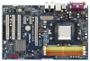
with x16 lane width graphics cards. PCIE2 / PCIE3 (PCIE x1 slot) is used for PCI Express cards with x1 lane width cards, such as Gigabit LAN card, SATA2 card, etc. Installing an expansion card Step 1. Before installing the expansion card, please make sure that the power supply is switched off or - ASRock ALiveNF5-VSTA | User Manual - Page 17
and pin3 on CLRCMOS1 for 5 seconds. However, please do not clear the CMOS right after you update the BIOS. If you need to clear the CMOS when you just finish updating the BIOS, you must boot up the system first, and then shut it down before you do the clear-CMOS action - ASRock ALiveNF5-VSTA | User Manual - Page 18
ATA 66/100/133 cable Note: Please refer to the instruction of your IDE device vendor for the details. SATAII_1 SATAII_3 (SATAII_4: see p.10, No. 12) These four Serial ATAII (SATAII) connectors support SATAII or SATA hard disk for internal storage devices. The current SATAII interface allows - ASRock ALiveNF5-VSTA | User Manual - Page 19
allows convenient connection and control of audio devices. 1. High Definition Audio supports Jack Sensing, but the panel wire on the chassis must support HDA to function correctly. Please follow the instruction in our manual and chassis manual to install your system. 2. If you use AC'97 audio panel - ASRock ALiveNF5-VSTA | User Manual - Page 20
wire to the ground pin. Though this motherboard provides 4-Pin CPU fan (Quiet Fan) support, the 3-Pin CPU fan still can work successfully even without the fan speed control function. If you plan to connect the 3-Pin CPU fan to the CPU fan connector on this motherboard, please connect it to Pin - ASRock ALiveNF5-VSTA | User Manual - Page 21
ATX 12V Power Connector (4-pin ATX12V1) (see p.10, No. 2) Please note that it is necessary to connect a power supply with ATX 12V plug to this connector. Failing to do so will cause power up failure. Game Port Header (15-pin GAME1) (see p.10, No. 22) HDMI_SPDIF Header (3-pin HDMI_SPDIF1) (see p.10 - ASRock ALiveNF5-VSTA | User Manual - Page 22
Guide of HDMI VGA card, please refer to the installation guide on page 16. Step 2. Connect the black end (A) VGA card, please refer to the user manual of HDMI VGA card vendor. Incorrect connection may card. Please refer to the VGA card user manual for connector usage in advance. Connect the HDMI - ASRock ALiveNF5-VSTA | User Manual - Page 23
guide. Some default setting of SATAII hard disks may not be at SATAII mode, which operate with the best performance. In order to enable SATAII function, please follow the below instruction website for details: http://www.hitachigst.com/hdd/support/download.htm The above examples are just for your - ASRock ALiveNF5-VSTA | User Manual - Page 24
the SATA / SATAII HDDs while the system is still power-on and in working condition. 2.11 Driver Installation Guide To install the drivers to your system, please insert the support CD to your optical drive first. Then, the drivers compatible to your system can be auto-detected and listed on the - ASRock ALiveNF5-VSTA | User Manual - Page 25
Mode" option to [AHCI]. STEP 2: Make a SATA / SATAII driver diskette. A. Insert the ASRock Support CD into your optical drive to boot your system. B. During POST at the beginning of system boot-up, press key, and then a window for boot devices selection appears. Please select CD- ROM as - ASRock ALiveNF5-VSTA | User Manual - Page 26
to boot your system, and follow the instruction to install Windows® VistaTM / Windows® VistaTM 64-bit OS on your system. When you see "Where do you want to install Windows?" page, please insert the ASRock Support CD into your optical drive, and click the "Load Driver" button on the left on the - ASRock ALiveNF5-VSTA | User Manual - Page 27
/ Windows® XP / Windows® XP 64-bit on your SATA / SATAII HDDs with RAID functions, please follow below steps. STEP 1: Set Up BIOS. A. Enter BIOS SETUP UTILITY Advanced screen IDE Configuration. B. Set the "SATA Operation Mode" option to [RAID]. STEP 2: Make a SATA / SATAII driver diskette - ASRock ALiveNF5-VSTA | User Manual - Page 28
to boot your system, and follow the instruction to install Windows® VistaTM / Windows® VistaTM 64-bit OS on your system. When you see "Where do you want to install Windows?" page, please insert the ASRock Support CD into your optical drive, and click the "Load Driver" button on the left on the - ASRock ALiveNF5-VSTA | User Manual - Page 29
Mode" to [RAID] in BIOS first. Then, please set the RAID configuration by using the Windows RAID installation guide in the following path in the Support CD: .. \ RAID Installation Guide 2.14 Untied Overclocking Technology This motherboard supports Untied Overclocking Technology, which means - ASRock ALiveNF5-VSTA | User Manual - Page 30
up the system time/date information Advanced To set up the advanced BIOS features H/W Monitor To display current hardware status Boot To set up To set up the security features Exit To exit the current screen or the BIOS SETUP UTILITY Use < > key or < > key to choose among the selections - ASRock ALiveNF5-VSTA | User Manual - Page 31
Boot Security Exit System Overview System Time System Date [17:00:09] [Fri 11/03/2006] BIOS Version : ALiveNF5-VSTA BIOS P1.0 Processor Type : AMD Athlon(tm) 64 Processor 3500+ (64bit supported) Processor Speed : 2200 MHz Microcode Update : 40FF2/0 L1 Cache Size : 128KB L2 Cache Size : 512KB - ASRock ALiveNF5-VSTA | User Manual - Page 32
CPU Configuration BIOS SETUP UTILITY Advanced CPU Configuration AM2 Boost Overclock Mode CPU Frequency (MHz) PCIE Frequency (MHz) Boot Failure Guard CPU the rated frequency/voltage. If Manual, multiplier and voltage will be AM2 Boost If you set this option to [Enabled], you will enable ASRock AM2 - ASRock ALiveNF5-VSTA | User Manual - Page 33
and [Disabled]. If you install Windows® VistaTM and want to enable Manual], you may adjust the value of Processor Multiplier and Processor Voltage. However, it is recommended to keep the default value for system stability. BIOS SETUP UTILITY Advanced CPU Configuration AM2 Boost Overclock Mode CPU - ASRock ALiveNF5-VSTA | User Manual - Page 34
the value of this item. Processor Voltage This item will show when "Multiplier/Voltage Change" is set to [Manual]; otherwise, it will be hidden. The range of the value depends on the CPU you adopt on this motherboard. However, for safety and system stability, it is not recommended to adjust the - ASRock ALiveNF5-VSTA | User Manual - Page 35
BIOS SETUP UTILITY Advanced Chipset Settings Onboard LAN Onboard HD Audio Front Panel CD-In Primary Graphics Adapter CPU-NB Link Speed CPU- OnBoard HD Audio. If you plan to use this motherboard to submit Windows® VistaTM logo test, please disable this option. Primary Graphics Adapter This - ASRock ALiveNF5-VSTA | User Manual - Page 36
Auto]. 3.3.3 ACPI Configuration BIOS SETUP UTILITY Advanced ACPI Settings Suspend To RAM Repost Video on STR Resume Away Mode Support Restore on AC / to suspend to RAM.) Away Mode Support Use this item to enable or disable Away Mode support under Windows® XP Media Center OS. The default value - ASRock ALiveNF5-VSTA | User Manual - Page 37
this motherboard to submit Windows® VistaTM certification. 3.3.4 IDE Configuration Advanced BIOS SETUP UTILITY IDE Configuration can not be accessed until you finish configuring RAID functions in NVIDIA BIOS / Windows RAID Utility. IDE Device Configuration You may set the IDE configuration for - ASRock ALiveNF5-VSTA | User Manual - Page 38
BIOS SETUP UTILITY Advanced IDE Master Device Vendor Size LBA Mode Block Mode PIO Mode Async DMA Ultra DMA S.M.A.R.T. :Hard Disk :MAXTOR 6L080J4 :80.0 GB :Supported :16Sectors :4 :MultiWord DMA-2 :Ultra DMA-6 :Supported hard disk > 512 MB under DOS and Windows; for Netware and UNIX user, select [ - ASRock ALiveNF5-VSTA | User Manual - Page 39
Enabled]. 32Bit Data Transfer Use this item to enable 32-bit access to maximize the IDE hard disk data transfer rate. 3.3.5 PCIPnP Configuration BIOS SETUP UTILITY Advanced Advanced PCI / PnP Settings WARNING: Setting wrong values in below sections may cause system to malfunction. Value in units - ASRock ALiveNF5-VSTA | User Manual - Page 40
Channel Parallel Port IRQ OnBoard Game Port OnBoard MIDI Port [Enabled] [3F8 / IRQ4] [Disabled] [378] [ECP + EPP] [1.9] [DMA3] [IRQ7] [Enabled] [Disabled] Allow BIOS to Enable or Disable Floppy Controller. +F1 F9 F10 ESC Select Screen Select Item Change Option General Help Load Defaults Save and - ASRock ALiveNF5-VSTA | User Manual - Page 41
the MIDI Port or disable it. Configuration options: [Disabled], [300], and [330]. 3.3.8 USB Configuration BIOS SETUP UTILITY Advanced USB Configuration USB Controller USB 2.0 Support Legacy USB Support [Enabled] [Enabled] [Disabled] To enable or disable the onboard USB controllers. +F1 F9 F10 - ASRock ALiveNF5-VSTA | User Manual - Page 42
there is no USB device connected, "Auto" option will disable the legacy USB support. 3.4 Hardware Health Event Monitoring Screen In this section, it allows you to of the CPU temperature, motherboard temperature, CPU fan speed, chassis fan speed, and the critical voltage. BIOS SETUP UTILITY - ASRock ALiveNF5-VSTA | User Manual - Page 43
General Help F9 Load Defaults F10 Save and Exit ESC Exit v02.54 (C) Copyright 1985-2003, American Megatrends, Inc. 3.5.1 Boot Settings Configuration BIOS SETUP UTILITY Boot Boot Settings Configuration Boot From Network Bootup Num-Lock [Disabled] [On] To enable or disable the boot from network - ASRock ALiveNF5-VSTA | User Manual - Page 44
you may set or change the supervisor/user password for the system. For the user password, you may also clear it. BIOS SETUP UTILITY Main Advanced H/W Monitor Boot Security Exit Security Settings Supervisor Password : Not Installed User Password : Not Installed Change Supervisor Password - ASRock ALiveNF5-VSTA | User Manual - Page 45
and exit setup?" Select [OK] to save the changes and exit the BIOS SETUP UTILITY. Discard Changes and Exit When you select this option, it message, "Discard changes and exit setup?" Select [OK] to exit the BIOS SETUP UTILITY without saving any changes. Discard Changes When you select this option - ASRock ALiveNF5-VSTA | User Manual - Page 46
4.1 Install Operating System This motherboard supports various Microsoft® Windows® operating systems: 2000 / XP / XP Media Center / XP 64-bit / VistaTM / VistaTM 64-bit. Because motherboard settings and hardware options vary, use the setup procedures in this chapter for general reference only - ASRock ALiveNF5-VSTA | User Manual - Page 47
feature, please make sure to install "AMD Processor Driver" from the "Support CD" first. If you are using Windows® 2000/XP operating system, please follow the instruction below to enable AMD's Cool 'n' QuietTM technology: 1. From the Windows® 2000/XP operating system, click the Start button. Select
-
 1
1 -
 2
2 -
 3
3 -
 4
4 -
 5
5 -
 6
6 -
 7
7 -
8
-
9
-
10
-
11
-
12
-
13
-
14
-
15
-
16
-
17
-
18
-
19
-
20
-
21
-
22
-
23
-
24
-
25
-
26
-
27
-
28
-
29
-
30
-
31
-
32
-
33
-
34
-
35
-
36
-
37
-
38
-
39
-
40
-
41
-
42
-
43
-
44
-
45
-
46
-
47
 |
 |

1
ALiveNF5-VSTA
User Manual
Version 1.0
Published January 2007
Copyright©2007 ASRock INC. All rights reserved.