ASRock ALiveNF5-eSATA2 User Manual
ASRock ALiveNF5-eSATA2 Manual
 |
View all ASRock ALiveNF5-eSATA2 manuals
Add to My Manuals
Save this manual to your list of manuals |
ASRock ALiveNF5-eSATA2 manual content summary:
- ASRock ALiveNF5-eSATA2 | User Manual - Page 1
ALiveNF5-eSATA2+ User Manual Version 1.0 Published January 2007 Copyright©2007 ASRock INC. All rights reserved. 1 - ASRock ALiveNF5-eSATA2 | User Manual - Page 2
purchaser for backup purpose, without written consent of ASRock Inc. Products and corporate names appearing in this manual may or may not be registered trademarks or copyrights USA ONLY The Lithium battery adopted on this motherboard contains Perchlorate, a toxic substance controlled in Perchlorate - ASRock ALiveNF5-eSATA2 | User Manual - Page 3
Windows® VistaTM Premium and Basic Logo 9 1.4 Motherboard Layout 10 1.5 HD 8CH I/O 11 2 . Installation 12 Pre-installation Precautions 12 2.1 CPU Installation 13 2.2 Installation of CPU SATA / SATAII HDDs .... 30 2.12 Driver Installation Guide 30 2.13 Installing Windows® 2000 / XP / XP 64-bit - ASRock ALiveNF5-eSATA2 | User Manual - Page 4
3.2 Main Screen 37 3.3 Advanced Screen 38 3.3.1 CPU Configuration 38 3.3.2 Chipset Configuration 42 3.3.3 ACPI Configuration 43 3.3.4 52 4 . Software Support 53 4.1 Install Operating System 53 4.2 Support CD Information 53 4.2.1 Running Support CD 53 4.2.2 Drivers Menu 53 4.2.3 Utilities - ASRock ALiveNF5-eSATA2 | User Manual - Page 5
of this manual occur, the updated version will be available on ASRock website without further notice. You may find the latest VGA cards and CPU support lists on ASRock website as well. ASRock website http://www.asrock.com 1.1 Package Contents 1 x ASRock ALiveNF5-eSATA2+ Motherboard (ATX Form Factor - ASRock ALiveNF5-eSATA2 | User Manual - Page 6
® nForce 520 - Dual Channel DDRII Memory Technology (see CAUTION 3) - 4 x DDRII DIMM slots - Support DDRII800/667/533 - Max. capacity: 8GB (see CAUTION 4) - CPU Frequency Stepless Control (see CAUTION 5) - ASRock U-COP (see CAUTION 6) - Boot Failure Guard (B.F.G.) - ASRock AM2 Boost: ASRock Patented - ASRock ALiveNF5-eSATA2 | User Manual - Page 7
CAUTION 11) - 4Mb AMI BIOS - AMI Legal BIOS - Supports "Plug and Play" - ACPI 1.1 Compliance Wake Up Events - Supports jumperfree - SMBIOS 2.3.1 Support - Drivers, Utilities, AntiVirus Software (Trial Version) - CPU Internal Temperature Sensing - CPU Ambient Temperature Sensing - Chassis Temperature - ASRock ALiveNF5-eSATA2 | User Manual - Page 8
. To improve heat dissipation, remember to spray thermal grease between the CPU and the heatsink when you install the PC system. 7. This motherboard supports ASRock AM2 Boost overclocking technology. If you enable this function in the BIOS setup, the memory performance will improve up to 12.5%, but - ASRock ALiveNF5-eSATA2 | User Manual - Page 9
For system integrators and users who purchase this motherboard and plan to submit Windows® VistaTM Premium and Basic logo, please follow the below table for minimum hardware requirement. CPU Memory VGA Sempron 2800+ 512MB Single Channel DX9.0 with WDDM Driver with 128bit VGA memory (Premium) with - ASRock ALiveNF5-eSATA2 | User Manual - Page 10
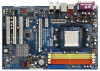
PS2_USB_PW1 Jumper 19 System Panel Header (PANEL1) 2 ATX 12V Power Connector (ATX12V1) 20 Chassis Speaker Header (SPEAKER 1) 3 CPU Fan Connector (CPU_FAN1) 21 NVIDIA nForce 520 Single Chip 4 AM2 940-Pin CPU Socket 22 Flash Memory 5 CPU Heatsink Retention Module 23 Floppy Connector (FLOPPY1 - ASRock ALiveNF5-eSATA2 | User Manual - Page 11
1.5 ASRock 8CH_eSATAII I/O 1 2 3 6 4 7 5 8 13 12 11 10 9 1 Parallel Port 2 RJ-45 Port 3 Side Speaker (Gray) 4 Rear 2nd output" to use front panel audio. Free Bundle ASRock provides you with one USB+1394 bracket, which can support 2 additional USB 2.0 ports and 1 IEEE 1394 port. 11 - ASRock ALiveNF5-eSATA2 | User Manual - Page 12
, peripherals, and/or components. 1. Unplug the power cord from the wall socket before touching any component. 2. To avoid damaging the motherboard components due to static electricity, NEVER place your motherboard directly on the carpet or the like. Also remember to use a grounded wrist strap - ASRock ALiveNF5-eSATA2 | User Manual - Page 13
Corner Small Triangle STEP 2 / STEP 3: Match The CPU Golden Triangle To The Socket Corner Small Triangle STEP 4: Push Down And Lock The Socket Lever 2.2 Installation of CPU Fan and Heatsink After you install the CPU into this motherboard, it is necessary to install a larger heatsink and cooling - ASRock ALiveNF5-eSATA2 | User Manual - Page 14
2.3 Installation of Memory Modules (DIMM) This motherboard provides four 240-pin DDRII (Double Data Rate II) DIMM slots, and supports Dual Channel Memory Technology. For dual channel configuration, you always need to install identical (the same brand, speed, size and chiptype) DDRII DIMM pair in - ASRock ALiveNF5-eSATA2 | User Manual - Page 15
matches the break on the slot. notch break notch break The DIMM only fits in one correct orientation. It will cause permanent damage to the motherboard and the DIMM if you force the DIMM into the slot at incorrect orientation. Step 3. Firmly insert the DIMM into the slot until the retaining - ASRock ALiveNF5-eSATA2 | User Manual - Page 16
the expansion card and make necessary hardware settings for the card before you start the installation. Step 2. Remove the system unit cover (if your motherboard is already installed in a chassis). Step 3. Remove the bracket facing the slot that you intend to use. Keep the screws for later use. Step - ASRock ALiveNF5-eSATA2 | User Manual - Page 17
short pin2 and pin3 on CLRCMOS1 for 5 seconds. However, please do not clear the CMOS right after you update the BIOS. If you need to clear the CMOS when you just finish updating the BIOS, you must boot up the system first, and then shut it down before you do the clear-CMOS action - ASRock ALiveNF5-eSATA2 | User Manual - Page 18
motherboard connect the black end to the IDE devices 80-conductor ATA 66/100/133 cable Note: Please refer to the instruction of your IDE device vendor for the details. Serial ATA II (PORT0) These four Serial ATAII (SATAII) connectors support SATA data cables for internal storage devices. The - ASRock ALiveNF5-eSATA2 | User Manual - Page 19
support SATA data cables for external SATAII function. The current eSATA II interface allows up to 3.0 Gb/s data transfer rate. Serial ATA (SATA) Data Cable (Optional) Either end of the SATA data cable can be connected to the SATA / SATAII hard disk or the SATAII connector on the motherboard - ASRock ALiveNF5-eSATA2 | User Manual - Page 20
allows convenient connection and control of audio devices. 1. High Definition Audio supports Jack Sensing, but the panel wire on the chassis must support HDA to function correctly. Please follow the instruction in our manual and chassis manual to install your system. 2. If you use AC'97 audio - ASRock ALiveNF5-eSATA2 | User Manual - Page 21
fan (Quiet Fan) support, the 3-Pin CPU fan still can work successfully even without the fan speed control function. If you plan to connect the 3-Pin CPU fan to the CPU fan connector on this motherboard, please connect it to Pin 1-3. Pin 1-3 Connected 3-Pin Fan Installation ATX Power Connector (20 - ASRock ALiveNF5-eSATA2 | User Manual - Page 22
+12V RXTPBP_0 GND RXTPAP_0 There are two IEEE 1394 headers on this motherboard, including one front panel IEEE 1394 header (FRONT_1394) and one back panel IEEE 1394 header (BACK_1394). Each IEEE 1394 header can support one IEEE 1394 port. 1 GND +5V SPDIFOUT HDMI_SPDIF header, providing - ASRock ALiveNF5-eSATA2 | User Manual - Page 23
the black end (A) of HDMI_SPDIF cable to the HDMI_SPDIF header on the motherboard. Then connect the white end (B or C) of HDMI_SPDIF cable to (3-pin) SPDIFOUT GND blue black USB+1394 Bracket This USB+1394 bracket can support 2 additional USB 2.0 ports and 1 IEEE 1394 port. Please connect the blue - ASRock ALiveNF5-eSATA2 | User Manual - Page 24
motherboard with a HDMI_SPDIF header. This motherboard motherboard. For the proper installation of HDMI VGA card, please refer to the installation guide manual of HDMI VGA card vendor. Incorrect connection may cause permanent damage to this motherboard Otherwise, the motherboard and the user manual for - ASRock ALiveNF5-eSATA2 | User Manual - Page 25
If you set "SATA Operation Mode" option in BIOS setup to non-RAID mode, Hot Plug function is not supported with eSATAII devices. If you still want to eSATAII_BOTTOM 1. If you just plan to install one eSATAII device to this motherboard, it is recommended to enable the bottom eSATAII port of the I/O - ASRock ALiveNF5-eSATA2 | User Manual - Page 26
connector (SATAII_RED (PORT1)) Connect the SATA data cable to the red eSATAII connector (eSATAII_BOTTOM) 2. If you plan to install two eSATAII devices to this motherboard, you need to enable both the top and the bottom eSATAII ports of the I/O shield. In order to enable the top and the bottom - ASRock ALiveNF5-eSATA2 | User Manual - Page 27
3. Use the eSATAII device cable to connect eSATAII device and the eSATAII port of the I/O shield according to the eSATAII connector that you connect the SATA data cable. Connect one end of the eSATAII device cable to eSATAII device Connect the other end of the eSATAII device cable to eSATAII port - ASRock ALiveNF5-eSATA2 | User Manual - Page 28
guide. Some default setting of SATAII hard disks may not be at SATAII mode, which operate with the best performance. In order to enable SATAII function, please follow the below instruction website for details: http://www.hitachigst.com/hdd/support/download.htm The above examples are just for your - ASRock ALiveNF5-eSATA2 | User Manual - Page 29
) Hard Disks Installation This motherboard adopts NVIDIA® nForce 520 chipset that supports Serial ATA (SATA) / Serial ATAII (SATAII) hard disks and RAID functions. You may install SATA / SATAII hard disks on this motherboard for internal storage devices. This section will guide you to install the - ASRock ALiveNF5-eSATA2 | User Manual - Page 30
Swap Functions for SATA / SATAII HDDs and eSATAII Devices This motherboard supports Hot Plug and Hot Swap functions for SATA / SATAII / eSATAII Devices in RAID / AHCI mode. NVIDIA® nForce 520 chipset provides hardware support for Advanced Host controller Interface (AHCI), a new programming interface - ASRock ALiveNF5-eSATA2 | User Manual - Page 31
Mode" option to [AHCI]. STEP 2: Make a SATA / SATAII driver diskette. A. Insert the ASRock Support CD into your optical drive to boot your system. B. During POST at the beginning of system boot-up, press key, and then a window for boot devices selection appears. Please select CD- ROM as - ASRock ALiveNF5-eSATA2 | User Manual - Page 32
to boot your system, and follow the instruction to install Windows® VistaTM / Windows® VistaTM 64-bit OS on your system. When you see "Where do you want to install Windows?" page, please insert the ASRock Support CD into your optical drive, and click the "Load Driver" button on the left on the - ASRock ALiveNF5-eSATA2 | User Manual - Page 33
/ VistaTM 64-bit are subject to change. Please visit our website for the updates of Windows® VistaTM / VistaTM 64-bit driver and related information in the future. 2. Before installing Windows® 2000 to your system, your Windows® 2000 optical disk is supposed to include SP4. If there is no SP4 - ASRock ALiveNF5-eSATA2 | User Manual - Page 34
Support CD: .. \ RAID Installation Guide STEP 3: Install Windows® VistaTM / VistaTM 64-bit OS on your system. Insert the Windows® VistaTM / Windows® VistaTM 64-bit optical disk into the optical drive to boot your system, and follow the instruction to install Windows® VistaTM / Windows® VistaTM - ASRock ALiveNF5-eSATA2 | User Manual - Page 35
Mode" to [RAID] in BIOS first. Then, please set the RAID configuration by using the Windows RAID installation guide in the following path in the Support CD: .. \ RAID Installation Guide 2.15 Untied Overclocking Technology This motherboard supports Untied Overclocking Technology, which means - ASRock ALiveNF5-eSATA2 | User Manual - Page 36
the BIOS SETUP UTILITY to configure your system. The Flash Memory on the motherboard stores the BIOS SETUP UTILITY. You may run the BIOS SETUP off and then back on. Because the BIOS software is constantly being updated, the following BIOS setup screens and descriptions are for reference purpose - ASRock ALiveNF5-eSATA2 | User Manual - Page 37
Overview System Time System Date [17:00:09] [Fri 01/12/2007] BIOS Version : ALiveNF5-eSATA2+ BIOS P1.0 Processor Type : AMD Athlon(tm) 64 X2 Dual Core Processor 4400+ (64bit supported) Processor Speed : 2892MHz Microcode Update : 60FB1/0 L1 Cache Size : 256KB L2 Cache Size : 1024KB Total Memory - ASRock ALiveNF5-eSATA2 | User Manual - Page 38
CPU Configuration BIOS SETUP UTILITY Advanced CPU Configuration AM2 Boost Overclock Mode CPU Frequency (MHz) PCIE Frequency (MHz) Boot Failure Guard CPU the rated frequency/voltage. If Manual, multiplier and voltage will be AM2 Boost If you set this option to [Enabled], you will enable ASRock AM2 - ASRock ALiveNF5-eSATA2 | User Manual - Page 39
], [Enabled] and [Disabled]. If you install Windows® VistaTM and want to enable this function, please Core AM2 CPU on this motherboard. C1E is an enhanced power saving state which is supported by AM2 dual ] by default. If it is set to [Manual], you may adjust the value of Processor Multiplier and - ASRock ALiveNF5-eSATA2 | User Manual - Page 40
BIOS SETUP UTILITY Advanced CPU Configuration AM2 Boost Overclock Mode CPU Frequency (MHz) PCIE Frequency (MHz) Boot Failure Guard CPU Change" is set to [Manual]; otherwise, it will be hidden. The range of the value depends on the CPU you adopt on this motherboard. However, for safety and system - ASRock ALiveNF5-eSATA2 | User Manual - Page 41
TRRD Use this to adjust TRRD values. Configuration options: [Auto], [2T], [3T], [4T], and [5T]. The default value is [Auto]. TRC Use this to adjust TRC values. Configuration options: [11T] to [26T]. The default value is [Auto]. MA Timing Use this to adjust values for MA timing. Configuration options - ASRock ALiveNF5-eSATA2 | User Manual - Page 42
BIOS SETUP UTILITY Advanced Chipset Settings Onboard LAN Onboard IEEE 1394 Onboard HD Audio Front Panel CD-In Primary Graphics Adapter CPU-NB Link Speed CPU of OnBoard HD Audio. If you plan to use this motherboard to submit Windows® VistaTM logo test, please disable this option. Primary Graphics - ASRock ALiveNF5-eSATA2 | User Manual - Page 43
3.3.3 ACPI Configuration BIOS SETUP UTILITY Advanced ACPI Settings Suspend To RAM Repost Video on STR Resume Away Mode Support Restore on AC STR refers to suspend to RAM.) Away Mode Support Use this item to enable or disable Away Mode support under Windows® XP Media Center OS. The default value is - ASRock ALiveNF5-eSATA2 | User Manual - Page 44
this motherboard to submit Windows® VistaTM certification. 3.3.4 IDE Configuration Advanced BIOS SETUP support RAID functions. IDE Device Configuration You may set the IDE configuration for the device that you specify. We will use the "IDE Master" as the example in the following instruction - ASRock ALiveNF5-eSATA2 | User Manual - Page 45
BIOS SETUP UTILITY Advanced IDE Master Device Vendor Size LBA Mode Block Mode PIO Mode Async DMA Ultra DMA S.M.A.R.T. :Hard Disk :MAXTOR 6L080J4 :80.0 GB :Supported :16Sectors :4 :MultiWord DMA-2 :Ultra DMA-6 :Supported hard disk > 512 MB under DOS and Windows; for Netware and UNIX user, select [ - ASRock ALiveNF5-eSATA2 | User Manual - Page 46
Enabled]. 32Bit Data Transfer Use this item to enable 32-bit access to maximize the IDE hard disk data transfer rate. 3.3.5 PCIPnP Configuration BIOS SETUP UTILITY Advanced Advanced PCI / PnP Settings WARNING: Setting wrong values in below sections may cause system to malfunction. Value in units - ASRock ALiveNF5-eSATA2 | User Manual - Page 47
Channel Parallel Port IRQ OnBoard Game Port OnBoard MIDI Port [Enabled] [3F8 / IRQ4] [Disabled] [378] [ECP + EPP] [1.9] [DMA3] [IRQ7] [Enabled] [Disabled] Allow BIOS to Enable or Disable Floppy Controller. +F1 F9 F10 ESC Select Screen Select Item Change Option General Help Load Defaults Save and - ASRock ALiveNF5-eSATA2 | User Manual - Page 48
the MIDI Port or disable it. Configuration options: [Disabled], [300], and [330]. 3.3.8 USB Configuration BIOS SETUP UTILITY Advanced USB Configuration USB Controller USB 2.0 Support Legacy USB Support [Enabled] [Enabled] [Disabled] To enable or disable the onboard USB controllers. +F1 F9 F10 - ASRock ALiveNF5-eSATA2 | User Manual - Page 49
you to monitor the status of the hardware on your system, including the parameters of the CPU temperature, motherboard temperature, CPU fan speed, chassis fan speed, and the critical voltage. BIOS SETUP UTILITY Main Advanced H/W Monitor Boot Security Exit Hardware Health Event Monitoring - ASRock ALiveNF5-eSATA2 | User Manual - Page 50
General Help F9 Load Defaults F10 Save and Exit ESC Exit v02.54 (C) Copyright 1985-2003, American Megatrends, Inc. 3.5.1 Boot Settings Configuration BIOS SETUP UTILITY Boot Boot Settings Configuration Boot From Network Bootup Num-Lock [Disabled] [On] To enable or disable the boot from network - ASRock ALiveNF5-eSATA2 | User Manual - Page 51
you may set or change the supervisor/user password for the system. For the user password, you may also clear it. BIOS SETUP UTILITY Main Advanced H/W Monitor Boot Security Exit Security Settings Supervisor Password : Not Installed User Password : Not Installed Change Supervisor Password - ASRock ALiveNF5-eSATA2 | User Manual - Page 52
and exit setup?" Select [OK] to save the changes and exit the BIOS SETUP UTILITY. Discard Changes and Exit When you select this option, it message, "Discard changes and exit setup?" Select [OK] to exit the BIOS SETUP UTILITY without saving any changes. Discard Changes When you select this option - ASRock ALiveNF5-eSATA2 | User Manual - Page 53
install the necessary drivers to activate the devices. 4.2.3 Utilities Menu The Utilities Menu shows the applications software that the motherboard supports. Click on a specific item then follow the installation wizard to install it. 4.2.4 Contact Information If you need to contact ASRock or want to - ASRock ALiveNF5-eSATA2 | User Manual - Page 54
this feature, please make sure to install "AMD Processor Driver" from the "Support CD" first. If you are using Windows® 2000/XP operating system, please follow the instruction below to enable AMD's Cool 'n' QuietTM technology: 1. From the Windows® 2000/XP operating system, click the Start button
-
 1
1 -
 2
2 -
 3
3 -
 4
4 -
 5
5 -
 6
6 -
 7
7 -
8
-
9
-
10
-
11
-
12
-
13
-
14
-
15
-
16
-
17
-
18
-
19
-
20
-
21
-
22
-
23
-
24
-
25
-
26
-
27
-
28
-
29
-
30
-
31
-
32
-
33
-
34
-
35
-
36
-
37
-
38
-
39
-
40
-
41
-
42
-
43
-
44
-
45
-
46
-
47
-
48
-
49
-
50
-
51
-
52
-
53
-
54
 |
 |

1
ALiveNF5-eSATA2+
User Manual
Version 1.0
Published January 2007
Copyright©2007 ASRock INC. All rights reserved.