ASRock ALiveNF5SLI-1394 User Manual
ASRock ALiveNF5SLI-1394 Manual
 |
View all ASRock ALiveNF5SLI-1394 manuals
Add to My Manuals
Save this manual to your list of manuals |
ASRock ALiveNF5SLI-1394 manual content summary:
- ASRock ALiveNF5SLI-1394 | User Manual - Page 1
ALiveNF5SLI-1394 User Manual Version 1.1 Published August 2007 Copyright©2007 ASRock INC. All rights reserved. 1 - ASRock ALiveNF5SLI-1394 | User Manual - Page 2
purchaser for backup purpose, without written consent of ASRock Inc. Products and corporate names appearing in this manual may or may not be registered trademarks or copyrights USA ONLY The Lithium battery adopted on this motherboard contains Perchlorate, a toxic substance controlled in Perchlorate - ASRock ALiveNF5SLI-1394 | User Manual - Page 3
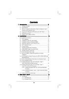
Table for Windows® VistaTM Premium 2007 and Basic Logo 9 1.4 Supported PCI Express VGA Card List for SLITM Mode 10 1.5 Motherboard Layout 11 1.6 ASRock 1394_eSATAII I/O Plus 12 2 . Installation 13 Pre-installation Precautions 13 2.1 CPU Installation 14 2.2 Installation of CPU Fan and - ASRock ALiveNF5SLI-1394 | User Manual - Page 4
3.2 Main Screen 41 3.3 Advanced Screen 42 3.3.1 CPU Configuration 42 3.3.2 Chipset Configuration 46 3.3.3 ACPI Configuration 47 3.3.4 56 4 . Software Support 57 4.1 Install Operating System 57 4.2 Support CD Information 57 4.2.1 Running Support CD 57 4.2.2 Drivers Menu 57 4.2.3 Utilities - ASRock ALiveNF5SLI-1394 | User Manual - Page 5
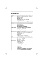
of this manual occur, the updated version will be available on ASRock website without further notice. You may find the latest VGA cards and CPU support lists on ASRock website as well. ASRock website http://www.asrock.com 1.1 Package Contents 1 x ASRock ALiveNF5SLI-1394 Motherboard (ATX Form - ASRock ALiveNF5SLI-1394 | User Manual - Page 6
® nForce 560 SLI - Dual Channel DDRII Memory Technology (see CAUTION 2) - 4 x DDRII DIMM slots - Support DDRII800/667/533 - Max. capacity: 8GB (see CAUTION 3) - CPU Frequency Stepless Control (see CAUTION 4) - ASRock U-COP (see CAUTION 5) - Boot Failure Guard (B.F.G.) - ASRock AM2 Boost: ASRock - ASRock ALiveNF5SLI-1394 | User Manual - Page 7
- 1 x IEEE 1394 header - CPU/Chassis FAN connector - 20 pin ATX power connector - 4 pin 12V power connector - SLI/XFIRE power connector - CD in header - Front panel audio connector - 2 x USB 2.0 headers (support 4 USB 2.0 ports) (see CAUTION 11) - 4Mb AMI BIOS - AMI Legal BIOS - Supports "Plug and - ASRock ALiveNF5SLI-1394 | User Manual - Page 8
. To improve heat dissipation, remember to spray thermal grease between the CPU and the heatsink when you install the PC system. 6. This motherboard supports ASRock AM2 Boost overclocking technology. If you enable this function in the BIOS setup, the memory performance will improve up to 12.5%, but - ASRock ALiveNF5SLI-1394 | User Manual - Page 9
SATAII connector, please read the "SATAII Hard Disk Setup Guide" on page 32 to adjust your SATAII hard disk drive to SATAII mode. You can also connect SATA hard disk to SATAII connector directly. 10. This motherboard supports eSATAII interface, the external SATAII specification. Please read "eSATAII - ASRock ALiveNF5SLI-1394 | User Manual - Page 10
PX7300GS TDH * MSI 7300GT-TD256EH Chipset Name GeForce 8800GTX GeForce 8600GT GeForce 7950GX2 GeForce Windows® XP / XP 64-bit OS. For the latest updates of the supported PCI Express VGA card list for SLITM Mode, please visit our website for details. ASRock website: http://www.asrock.com/support - ASRock ALiveNF5SLI-1394 | User Manual - Page 11
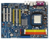
AM2 940-Pin CPU Socket 23 Infrared Module Header (IR1) 6 NVIDIA nForce 560 SLI Chipset 24 Front Panel IEEE 1394 Header 7 ATX 12V Power Connector (ATX12V1) (FRONT_1394) 8 2 x 240-pin DDRII DIMM Slots 25 Floppy Connector (FLOPPY1) (Dual Channel A: DDRII_1, DDRII_2; Yellow) 26 Game Port Header - ASRock ALiveNF5SLI-1394 | User Manual - Page 12
1.6 ASRock 1394_eSATAII I/O Plus 1 PS/2 Mouse Port (Green) 2 Parallel Port 3 IEEE 1394 Port 4 RJ-45 Port 5 Side Speaker (Gray) 6 Rear Speaker (Black) 7 Central / Bass (Orange) 8 Line In (Light Blue) * 9 Front Speaker (Lime) 10 Microphone (Pink) 11 USB 2.0 Ports (USB23) 12 USB 2.0 Ports (USB01) 13 - ASRock ALiveNF5SLI-1394 | User Manual - Page 13
, peripherals, and/or components. 1. Unplug the power cord from the wall socket before touching any component. 2. To avoid damaging the motherboard components due to static electricity, NEVER place your motherboard directly on the carpet or the like. Also remember to use a grounded wrist strap - ASRock ALiveNF5SLI-1394 | User Manual - Page 14
. Make sure that the CPU and the heatsink are securely fastened and in good contact with each other. Then connect the CPU fan to the CPU FAN connector (CPU_FAN1, see Page 11, No. 36). For proper installation, please kindly refer to the instruction manuals of the CPU fan and the heatsink. 14 - ASRock ALiveNF5SLI-1394 | User Manual - Page 15
2.3 Installation of Memory Modules (DIMM) This motherboard provides four 240-pin DDRII (Double Data Rate II) DIMM slots, and supports Dual Channel Memory Technology. For dual channel configuration, you always need to install identical (the same brand, speed, size and chiptype) DDRII DIMM pair in - ASRock ALiveNF5SLI-1394 | User Manual - Page 16
matches the break on the slot. notch break notch break The DIMM only fits in one correct orientation. It will cause permanent damage to the motherboard and the DIMM if you force the DIMM into the slot at incorrect orientation. Step 3. Firmly insert the DIMM into the slot until the retaining - ASRock ALiveNF5SLI-1394 | User Manual - Page 17
SLITM Mode PCI Express VGA cards, please refer to the "Supported PCI Express VGA Card List for SLITM Mode" on page 10. PCIE3 (PCIE x16 slot) is used for PCI Express cards with x16 lane width graphics cards. 1. This motherboard supports NVIDIA® SLITM technology. PCIE2 and PCIE4 slots (yellow) are - ASRock ALiveNF5SLI-1394 | User Manual - Page 18
Guide This motherboard supports NVIDIA® SLITM (Scalable Link Interface) technology that allows you to install two identical NVIDIA® SLITM enabled PCI Express x16 graphics cards. Currently, NVIDIA® SLITM technology supports Windows® XP, XP . Step3. If required, connect an auxiliary power source to - ASRock ALiveNF5SLI-1394 | User Manual - Page 19
cable to SLI/XFIRE power connector. Step6. Install the graphics card drivers to your system. After that, you can enable the Multi-Graphics Processing Unit (GPU) feature in the NVIDIA® nView system tray utility. Please follow the below procedures to enable the multiGPU feature. For Windows® XP - ASRock ALiveNF5SLI-1394 | User Manual - Page 20
E. From the Display Properties dialog box, select the Settings tab then click Advanced. F. Select the NVIDIA GeForce tab. G. Click the slider to display the following screen, then select the SLI multi-GPU item. H. Click the Enable SLI multi-GPU check box. I. Click OK when done. 20 - ASRock ALiveNF5SLI-1394 | User Manual - Page 21
® VistaTM / VistaTM 64-bit OS: A. Click the Start icon on your Windows taskbar. B. From the pop-up menu, select All Programs, and then click NVIDIA Corporation. C. Select NVIDIA Control Panel tab. D. Select Control Panel tab. E. From the - ASRock ALiveNF5SLI-1394 | User Manual - Page 22
short pin2 and pin3 on CLRCMOS1 for 5 seconds. However, please do not clear the CMOS right after you update the BIOS. If you need to clear the CMOS when you just finish updating the BIOS, you must boot up the system first, and then shut it down before you do the clear-CMOS action - ASRock ALiveNF5SLI-1394 | User Manual - Page 23
) PIN1 IDE1 PIN1 IDE2 connect the blue end to the motherboard connect the black end to the IDE devices 80-conductor ATA 66/100/133 cable Note: If you use only one IDE device on this motherboard, please set the IDE device as "Master". Please refer to the instruction of your IDE device vendor - ASRock ALiveNF5SLI-1394 | User Manual - Page 24
or the SATAII connector on this motherboard. You can also use the SATA data cable to connect SATAII_RED (PORT 2.1) connector and eSATAII connector. Serial ATA (SATA) Power Cable (Optional) connect to the SATA HDD power connector connect to the power supply Please connect the black end of SATA - ASRock ALiveNF5SLI-1394 | User Manual - Page 25
) (see p.11, No. 36) Please connect the CPU fan 1 GND cable to this connector and 2 +12V 3 CPU_FAN_SPEED match the black wire to the 4 FAN_SPEED_CONTROL ground pin. Though this motherboard provides 4-Pin CPU fan (Quiet Fan) support, the 3-Pin CPU fan still can work successfully even - ASRock ALiveNF5SLI-1394 | User Manual - Page 26
RXTPBM_0 +12V GND 1 +12V RXTPBP_0 GND RXTPAP_0 Connect a Game cable to this header if the Game port bracket is installed. Besides one default IEEE 1394 port on the I/O panel, there is one IEEE 1394 header (FRONT_1394) on this motherboard. This IEEE 1394 header can support one IEEE 1394 port. 26 - ASRock ALiveNF5SLI-1394 | User Manual - Page 27
HDMI_SPDIF connector of HDMI VGA card to this header. HDMI_SPDIF Cable (Optional) C B A Please connect the black end (A) of HDMI_SPDIF cable to the HDMI_SPDIF header on the motherboard. Then connect the white end (B or C) of HDMI_SPDIF cable to the HDMI_SPDIF connector of HDMI VGA card. A. black - ASRock ALiveNF5SLI-1394 | User Manual - Page 28
connectors on HDMI VGA card, please refer to the user manual of HDMI VGA card vendor. Incorrect connection may cause permanent damage to this motherboard and the HDMI VGA card. Step 3. Connect the white end (B or C) of HDMI_SPDIF cable to the HDMI_SPDIF connector of HDMI VGA card. (There are - ASRock ALiveNF5SLI-1394 | User Manual - Page 29
motherboard supports eSATAII hard disk to the eSATAII ports instead of opening your chassis to exchange IEEE 1394 to be a trend for external interface. NOTE: 1. If you set "SATA Operation Mode" option in BIOS setup to RAID mode and enable the option "eSATAII Support", Hot Plug function is supported - ASRock ALiveNF5SLI-1394 | User Manual - Page 30
) with a SATA data cable first. Connect the SATA data cable to the red SATAII connector (SATAII_RED (PORT 2.1)) Connect the SATA data cable to the eSATAII connector (eSATAII_TOP) 2. Use the eSATAII device cable to connect eSATAII device and the eSATAII port of the I/O shield. Connect one end of - ASRock ALiveNF5SLI-1394 | User Manual - Page 31
Comparison between eSATAII and other devices IEEE 1394 USB 2.0 SATA eSATAII/SATAII 400Mb/s 480Mb/s 1.5Gb/s (1500Mb/s) 3.0Gb/s (3000Mb/s) 31 - ASRock ALiveNF5SLI-1394 | User Manual - Page 32
guide. Some default setting of SATAII hard disks may not be at SATAII mode, which operate with the best performance. In order to enable SATAII function, please follow the below instruction 's website for details: http://www.hitachigst.com/hdd/support/download.htm The above examples are just for your - ASRock ALiveNF5SLI-1394 | User Manual - Page 33
Hard Disks Installation This motherboard adopts NVIDIA® nForce 560 SLI chipset that supports Serial ATA (SATA) / Serial ATAII (SATAII) hard disks and RAID functions. You may install SATA / SATAII hard disks on this motherboard for internal storage devices. This section will guide you to install the - ASRock ALiveNF5SLI-1394 | User Manual - Page 34
Swap Functions for SATA / SATAII HDDs and eSATAII Devices This motherboard supports Hot Plug and Hot Swap functions for SATA / SATAII / to the eSATAII ports instead of opening your chassis to exchange your SATAII hard disk. Hot Plug and Hot Swap functions are not supported under Windows® VistaTM and - ASRock ALiveNF5SLI-1394 | User Manual - Page 35
is installed into system properly. The latest SATA / SATAII driver is available on our support website: www.asrock.com 4. Make sure to use the SATA power cable & data cable, which are from our motherboard package. 5. Please follow below instructions step by step to reduce the risk of HDD crash or - ASRock ALiveNF5SLI-1394 | User Manual - Page 36
follow below instruction sequence to process the Hot Plug, improper procedure will cause the SATA / SATAII HDD damage and data loss. Step 1 Please connect SATA power cable 1x4-pin end Step 2 Connect SATA data cable to (White) to the power supply 1x4-pin cable. the motherboard's SATAII connector - ASRock ALiveNF5SLI-1394 | User Manual - Page 37
to your system can be auto-detected and listed on the support CD driver page. Please follow the order from up to bottom side to install those required drivers. Therefore, the drivers you install can work properly. 2.15 Installing Windows® 2000 / XP / XP 64-bit / VistaTM / VistaTM 64-bit Without RAID - ASRock ALiveNF5SLI-1394 | User Manual - Page 38
refer to the BIOS RAID installation guide in the following path in the Support CD: .. \ RAID Installation Guide STEP 4: Install Windows® 2000 / Windows® XP / Windows® XP 64-bit OS on your system. After step 1, 2, 3, you can start to install Windows® 2000 / Windows® XP / Windows® XP 64-bit OS - ASRock ALiveNF5SLI-1394 | User Manual - Page 39
to boot your system, and follow the instruction to install Windows® VistaTM / Windows® VistaTM 64-bit OS on your system. When you see "Where do you want to install Windows?" page, please insert the ASRock Support CD into your optical drive, and click the "Load Driver" button on the left on the - ASRock ALiveNF5SLI-1394 | User Manual - Page 40
the BIOS SETUP UTILITY to configure your system. The Flash Memory on the motherboard stores the BIOS SETUP UTILITY. You may run the BIOS SETUP off and then back on. Because the BIOS software is constantly being updated, the following BIOS setup screens and descriptions are for reference purpose - ASRock ALiveNF5SLI-1394 | User Manual - Page 41
System Overview System Time System Date [17:00:09] [Sat 06/23/2007] BIOS Version : ALiveNF5SLI-1394 BIOS P1.00 Processor Type : AMD Athlon(tm) 64 Processor 3500+ (64bit) Processor Speed : 2200 MHz Microcode Update : 40FF2/0 L1 Cache Size : 128KB L2 Cache Size : 512KB Total Memory DDRII1 DDRII2 - ASRock ALiveNF5SLI-1394 | User Manual - Page 42
CPU Configuration BIOS SETUP UTILITY Advanced CPU Configuration AM2 Boost Overclock Mode CPU Frequency (MHz) PCIE Frequency (MHz) Boot Failure Guard CPU the rated frequency/voltage. If Manual, multiplier and voltage will be AM2 Boost If you set this option to [Enabled], you will enable ASRock AM2 - ASRock ALiveNF5SLI-1394 | User Manual - Page 43
or disable the feature of Boot Failure Guard. CPU Spread Spectrum This feature will be set to [ Auto], [Enabled] and [Disabled]. If you install Windows® VistaTM and want to enable this function, please Auto] by default. If it is set to [Manual], you may adjust the value of Processor Multiplier and - ASRock ALiveNF5SLI-1394 | User Manual - Page 44
BIOS SETUP UTILITY Advanced CPU Configuration AM2 Boost Overclock Mode CPU Frequency (MHz) PCIE Frequency (MHz) Boot Failure Guard CPU Change" is set to [Manual]; otherwise, it will be hidden. The range of the value depends on the CPU you adopt on this motherboard. However, for safety and system - ASRock ALiveNF5SLI-1394 | User Manual - Page 45
TRRD Use this to adjust TRRD values. Configuration options: [Auto], [2T], [3T], [4T], and [5T]. The default value is [Auto]. TRC Use this to adjust TRC values. Configuration options: [11T] to [26T]. The default value is [Auto]. MA Timing Use this to adjust values for MA timing. Configuration options - ASRock ALiveNF5SLI-1394 | User Manual - Page 46
3.3.2 Chipset Configuration BIOS SETUP UTILITY Advanced Chipset Settings Onboard LAN OnBoard UAA Audio Onboard IEEE 1394 Primary Graphics Adapter CPU-NB Link Speed CPU-NB Link Width DRAM Voltage NBCORE Voltage [Enabled] [Auto] [Enabled] [PCI] [Auto] [Auto] [Auto] [Auto] To set DRAM Voltage. +F1 - ASRock ALiveNF5SLI-1394 | User Manual - Page 47
3.3.3 ACPI Configuration BIOS SETUP UTILITY Advanced ACPI Settings Suspend To RAM Away Mode Support Restore on AC / Power Loss . (STR refers to suspend to RAM.) Away Mode Support Use this item to enable or disable Away Mode support under Windows® XP Media Center OS. The default value is [Disabled]. - ASRock ALiveNF5SLI-1394 | User Manual - Page 48
motherboard to submit Windows® VistaTM certification. 3.3.4 IDE Configuration BIOS SETUP ports can support RAID functions. IDE Device Configuration You may set the IDE configuration for the device that you specify. We will use the "Primary IDE Master" as the example in the following instruction - ASRock ALiveNF5SLI-1394 | User Manual - Page 49
Supported :16Sectors :4 :MultiWord DMA-2 :Ultra DMA-6 :Supported Type LBA/Large Mode Block (Multi-Sector Transfer) PIO Mode DMA Mode S.M.A.R.T. 32Bit Data Transfer [Auto] [Auto] [Auto] [Auto] [Auto] [Disabled] [Disabled] Select the type of device connected into BIOS, use DOS and Windows; for - ASRock ALiveNF5SLI-1394 | User Manual - Page 50
], [Enabled]. 32Bit Data Transfer Use this item to enable 32-bit access to maximize the IDE hard disk data transfer rate. 3.3.5 PCIPnP Configuration BIOS SETUP UTILITY Advanced Advanced PCI / PnP Settings PCI Latency Timer PCI IDE BusMaster [32] [Enabled] Value in units of PCI clocks for PCI - ASRock ALiveNF5SLI-1394 | User Manual - Page 51
drive. BIOS SETUP UTILITY Advanced Floppy Configuration Floppy A [1.44 MB 312"] Select the type of floppy drive connected to the or disable floppy drive controller. Serial Port Address Use this item to set the address for the onboard serial port or disable it. Configuration options: [Disabled - ASRock ALiveNF5SLI-1394 | User Manual - Page 52
this itme to select the address for the MIDI Port or disable it. Configuration options: [Disabled], [300], and [330]. 3.3.8 USB Configuration BIOS SETUP UTILITY Advanced USB Configuration USB Controller USB 2.0 Support Legacy USB Support [Enabled] [Enabled] [Disabled] To enable or disable the - ASRock ALiveNF5SLI-1394 | User Manual - Page 53
USB device connected, "Auto" option will disable the legacy USB support. 3.4 Hardware Health Event Monitoring Screen In this section, it allows you to monitor the status of the hardware on your system, including the parameters of the CPU temperature, motherboard temperature, CPU fan speed, chassis - ASRock ALiveNF5SLI-1394 | User Manual - Page 54
General Help F9 Load Defaults F10 Save and Exit ESC Exit v02.54 (C) Copyright 1985-2003, American Megatrends, Inc. 3.5.1 Boot Settings Configuration BIOS SETUP UTILITY Boot Boot Settings Configuration Boot From Network Bootup Num-Lock [Disabled] [On] To enable or disable the boot from network - ASRock ALiveNF5SLI-1394 | User Manual - Page 55
you may set or change the supervisor/user password for the system. For the user password, you may also clear it. BIOS SETUP UTILITY Main Advanced H/W Monitor Boot Security Exit Security Settings Supervisor Password : Not Installed User Password : Not Installed Change Supervisor Password - ASRock ALiveNF5SLI-1394 | User Manual - Page 56
and exit setup?" Select [OK] to save the changes and exit the BIOS SETUP UTILITY. Discard Changes and Exit When you select this option, it message, "Discard changes and exit setup?" Select [OK] to exit the BIOS SETUP UTILITY without saving any changes. Discard Changes When you select this option - ASRock ALiveNF5SLI-1394 | User Manual - Page 57
4.1 Install Operating System This motherboard supports various Microsoft® Windows® operating systems: 2000 / XP / XP Media Center / XP 64-bit / VistaTM / VistaTM 64-bit. Because motherboard settings and hardware options vary, use the setup procedures in this chapter for general reference only
-
 1
1 -
 2
2 -
 3
3 -
 4
4 -
 5
5 -
 6
6 -
 7
7 -
8
-
9
-
10
-
11
-
12
-
13
-
14
-
15
-
16
-
17
-
18
-
19
-
20
-
21
-
22
-
23
-
24
-
25
-
26
-
27
-
28
-
29
-
30
-
31
-
32
-
33
-
34
-
35
-
36
-
37
-
38
-
39
-
40
-
41
-
42
-
43
-
44
-
45
-
46
-
47
-
48
-
49
-
50
-
51
-
52
-
53
-
54
-
55
-
56
-
57
 |
 |

1
ALiveNF5SLI-1394
User Manual
Version 1.1
Published August 2007
Copyright©2007 ASRock INC. All rights reserved.