ASRock ALiveNF6G-DVI User Manual
ASRock ALiveNF6G-DVI Manual
 |
View all ASRock ALiveNF6G-DVI manuals
Add to My Manuals
Save this manual to your list of manuals |
ASRock ALiveNF6G-DVI manual content summary:
- ASRock ALiveNF6G-DVI | User Manual - Page 1
ALiveNF6G-DVI ALiveNF6G-VSTA User Manual Version 1.3 Published December 2006 Copyright©2006 ASRock INC. All rights reserved. 1 - ASRock ALiveNF6G-DVI | User Manual - Page 2
purchaser for backup purpose, without written consent of ASRock Inc. Products and corporate names appearing in this manual may or may not be registered trademarks or copyrights USA ONLY The Lithium battery adopted on this motherboard contains Perchlorate, a toxic substance controlled in Perchlorate - ASRock ALiveNF6G-DVI | User Manual - Page 3
Table for Windows® VistaTM Premium and Basic Logo 9 1.4 Motherboard Layout (ALiveNF6G-DVI 10 1.5 Motherboard Layout (ALiveNF6G-VSTA 11 1.6 HD 8CH I/O (ALiveNF6G-DVI / ALiveNF6G-VSTA 12 2 . Installation 13 Pre-installation Precautions 13 2.1 CPU Installation 14 2.2 Installation of CPU Fan and - ASRock ALiveNF6G-DVI | User Manual - Page 4
Settings Configuration 46 3.6 Security Screen 47 3.7 Exit Screen 48 4 . Software Support 49 4.1 Install Operating System 49 4.2 Support CD Information 49 4.2.1 Running Support CD 49 4.2.2 Drivers Menu 49 4.2.3 Utilities Menu 49 4.2.4 Contact Information 49 APPENDIX: AMD's Cool 'n' QuietTM - ASRock ALiveNF6G-DVI | User Manual - Page 5
this manual occur, the updated version will be available on ASRock website without further notice. You may find the latest VGA cards and CPU support lists on ASRock website as well. ASRock website http://www.asrock.com 1.1 Package Contents 1 x ASRock ALiveNF6G-DVI / ALiveNF6G-VSTA Motherboard (Micro - ASRock ALiveNF6G-DVI | User Manual - Page 6
1.2 Specifications Platform CPU Chipset Memory Hybrid Booster Expansion Slot Graphics Audio LAN Rear Panel I/O - Micro ATX Form Factor: 9.6-in x 9.6-in, 24.4 cm x 24.4 cm - Socket AM2 for AMD AthlonTM 64FX / 64X2 / 64 and Sempron Processors - AMD LIVE!TM Ready - Supports AMD's Cool 'n' QuietTM - ASRock ALiveNF6G-DVI | User Manual - Page 7
panel audio connector - 3 x USB 2.0 headers (support 6 USB 2.0 ports) (see CAUTION 11) - 4Mb AMI BIOS - AMI Legal BIOS - Supports "Plug and Play" - ACPI 1.1 Compliance Wake Up Events - Supports jumperfree - SMBIOS 2.3.1 Support - Drivers, Utilities, AntiVirus Software (Trial Version) - CPU Internal - ASRock ALiveNF6G-DVI | User Manual - Page 8
system. 8. This motherboard supports ASRock AM2 Boost overclocking technology. If you enable this function in the BIOS setup, the memory performance will improve up to 12.5%, but the effect still depends on the AM2 CPU you adopt. Enabling this function will overclock the chipset/CPU reference clock - ASRock ALiveNF6G-DVI | User Manual - Page 9
://www.asrock.com 1.3 Minimum Hardware Requirement Table for Windows® VistaTM Premium and Basic Logo For system integrators and users who purchase this motherboard and plan to submit Windows® VistaTM Premium and Basic logo, please follow the below table for minimum hardware requirement. CPU Memory - ASRock ALiveNF6G-DVI | User Manual - Page 10
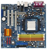
RESET 26 25 24 23 22 21 20 19 18 SATAII 4Mb BIOS CHA_FAN1 USB2.0 10 11 12 13 14 15 16 17 1 PS2_USB_PW1 Jumper 2 ATX 12V Power Connector (ATX12V1) 3 CPU Heatsink Retention Module 4 AM2 940-Pin CPU Socket 5 CPU Fan Connector (CPU_FAN1) 6 2 x 240-pin DDRII DIMM Slots (Dual Channel A: DDRII_1 - ASRock ALiveNF6G-DVI | User Manual - Page 11
18 SATAII 4Mb BIOS CHA_FAN1 USB2.0 10 11 12 13 14 15 16 17 1 PS2_USB_PW1 Jumper 17 USB 2.0 Header (USB6_7, Blue) 2 ATX 12V Power Connector (ATX12V1) 18 System Panel Header (PANEL1) 3 CPU Heatsink Retention Module 19 USB 2.0 Header (USB8_9, Blue) 4 AM2 940-Pin CPU Socket 20 USB 2.0 Header - ASRock ALiveNF6G-DVI | User Manual - Page 12
1.6 HD 8CH I/O (ALiveNF6G-DVI / ALiveNF6G-VSTA) 1 2 3 6 4 7 5 8 13 12 11 10 9 1 Parallel Port 2 RJ-45 Port 3 Side Speaker (Gray) 4 Rear Speaker (Black) 5 Central / Bass (Orange) 6 Line In (Light Blue) *7 Front Speaker (Lime) 8 Microphone (Pink) 9 USB 2.0 Ports (USB01) 10 USB 2.0 Ports ( - ASRock ALiveNF6G-DVI | User Manual - Page 13
, peripherals, and/or components. 1. Unplug the power cord from the wall socket before touching any component. 2. To avoid damaging the motherboard components due to static electricity, NEVER place your motherboard directly on the carpet or the like. Also remember to use a grounded wrist strap - ASRock ALiveNF6G-DVI | User Manual - Page 14
. Make sure that the CPU and the heatsink are securely fastened and in good contact with each other. Then connect the CPU fan to the CPU FAN connector (CPU_FAN1, see Page 10 / 11, No. 5). For proper installation, please kindly refer to the instruction manuals of the CPU fan and the heatsink - ASRock ALiveNF6G-DVI | User Manual - Page 15
of Memory Modules (DIMM) This motherboard provides four 240-pin DDRII (Double Data Rate II) DIMM slots, and supports Dual Channel Memory Technology. DDRII_4; Orange slots; see p.10/p.11 No.7), so that Dual Channel Memory Technology can be activated. This motherboard also allows you to install four - ASRock ALiveNF6G-DVI | User Manual - Page 16
matches the break on the slot. notch break notch break The DIMM only fits in one correct orientation. It will cause permanent damage to the motherboard and the DIMM if you force the DIMM into the slot at incorrect orientation. Step 3. Firmly insert the DIMM into the slot until the retaining - ASRock ALiveNF6G-DVI | User Manual - Page 17
ASRock DVI Graphics-SI card (ALiveNF6GDVI). PCIE2 (PCIE x1 slot) is used for PCI Express cards with x1 lane width cards, such as Gigabit LAN card, SATA2 card, etc. You can only choose either PCI Express VGA card or DVI Graphics-SI card to install to PCIE1 (PCIE x16 slot) on ALiveNF6G-DVI motherboard - ASRock ALiveNF6G-DVI | User Manual - Page 18
2.5 Easy Dual Monitor Feature (ALiveNF6G-DVI) This motherboard supports Dual Monitor feature. With the onboard VGA/D-Sub output and the external installation of our DVI Graphics-SI card, this motherboard provides users with dual VGA output support: DVI-D and D-Sub ports. You can easily enjoy the - ASRock ALiveNF6G-DVI | User Manual - Page 19
NVIDIA® VGA driver from our support CD to your system and restart your computer. Then you can start to use DVI-D output function with this motherboard. Righ click the "NVIDIA Settings" icon on on the desktop to adjust the display mode you plan to use by following the instructions shown on the - ASRock ALiveNF6G-DVI | User Manual - Page 20
Feature (ALiveNF6G-DVI / ALiveNF6G-VSTA) This motherboard supports Multi memory. If you do not adjust the BIOS setup, the default value of "Share Memory", [Auto], will disable onboard VGA/D-Sub function when the add-on VGA card is inserted to this motherboard. 4. Install the onboard VGA driver - ASRock ALiveNF6G-DVI | User Manual - Page 21
1_2 2_3 Short pin2, pin3 to enable (see p.10/p.11, No. 1) +5V +5VSB +5VSB (standby) for PS/2 or USB wake up events. Note: To select +5VSB, it not clear the CMOS right after you update the BIOS. If you need to clear the CMOS when you just finish updating the BIOS, you must boot up the system - ASRock ALiveNF6G-DVI | User Manual - Page 22
the connector. Primary IDE connector (Blue) (39-pin IDE1, see p.10/p.11 No. 11) PIN1 IDE1 connect the blue end to the motherboard connect the black end to the IDE devices 80-conductor ATA 66/100/133 cable Note: Please refer to the instruction of your IDE device vendor for the details. Serial - ASRock ALiveNF6G-DVI | User Manual - Page 23
the I/O panel, there are three USB 2.0 headers on this motherboard. Each USB 2.0 header can support two USB 2.0 ports. (9-pin USB6_7) (see p.10/p.11 No. 17) (9-pin USB4_5) (see p.10/p.11 No. 20) Infrared Module Header (5-pin IR1) (see p.10/p.11 No. 8) Internal Audio Connectors (4-pin CD1) (CD1: see - ASRock ALiveNF6G-DVI | User Manual - Page 24
panel only. You don't need to connect them for AC'97 audio panel. E. Enter BIOS Setup Utility. Enter Advanced Settings, and then select Chipset Configuration. Set the Front Panel Control option from [Auto] to [Enabled]. F. Enter Windows system. Click the icon on the lower right hand taskbar to - ASRock ALiveNF6G-DVI | User Manual - Page 25
pin GAME1) (see p.10/p.11 No. 9) Serial port Header (9-pin COM1) (see p.10/p.11 No.33) HDMI_SPDIF Header (3-pin HDMI_SPDIF1) (see p.10/p.11 No. 27) HDMI_SPDIF DDCD#1 This COM1 header supports a serial port module. 1 GND SPDIFOUT +5V HDMI_SPDIF header, providing SPDIF audio output to HDMI VGA card - ASRock ALiveNF6G-DVI | User Manual - Page 26
motherboard with a HDMI_SPDIF header. This motherboard is equipped with a HDMI_SPDIF header, which provides SPDIF audio guide on page 17. Step 2. Connect the black end (A) of HDMI_SPDIF cable to the HDMI_SPDIF header (HDMI_SPDIF1, yellow, see page 10 / 11, No. 27) on the motherboard user manual for - ASRock ALiveNF6G-DVI | User Manual - Page 27
guide. Some default setting of SATAII hard disks may not be at SATAII mode, which operate with the best performance. In order to enable SATAII function, please follow the below instruction website for details: http://www.hitachigst.com/hdd/support/download.htm The above examples are just for your - ASRock ALiveNF6G-DVI | User Manual - Page 28
/ nForce 430 or GeForce 6150SE / nForce 430 chipset that supports Serial ATA (SATA) / Serial ATAII (SATAII) hard disks and RAID functions. You may install SATA / SATAII hard disks on this motherboard for internal storage devices. This section will guide you to install the SATA / SATAII hard disks - ASRock ALiveNF6G-DVI | User Manual - Page 29
. 1. Insert HDMR card to HDMR slot on this motherboard. Please make sure that the HDMR card is completely seated on the slot. 2. Install HDMR card driver from our support CD to your system. 3. Reboot your system. 2.15 Installing Windows® 2000 / XP / XP 64-bit / VistaTM / VistaTM 64-bit Without RAID - ASRock ALiveNF6G-DVI | User Manual - Page 30
64-bit With RAID Functions If you want to install Windows® 2000, Windows® XP or Windows® XP 64-bit on your SATA / SATAII HDDs with RAID functions, please follow below steps. STEP 1: Make a SATA / SATAII Driver Diskette. A. Insert the ASRock Support CD into your optical drive to boot your system - ASRock ALiveNF6G-DVI | User Manual - Page 31
Mode" to [RAID] in BIOS first. Then, please set the RAID configuration by using the Windows RAID installation guide in the following path in the Support CD: .. \ RAID Installation Guide 2.17 Untied Overclocking Technology This motherboard supports Untied Overclocking Technology, which means during - ASRock ALiveNF6G-DVI | User Manual - Page 32
3.1 Introduction This section explains how to use the BIOS SETUP UTILITY to configure your system. The Flash Memory on the motherboard stores the BIOS SETUP UTILITY. You may run the BIOS SETUP UTILITY when you start up the computer. Please press during the Power-On-Self-Test (POST) to enter - ASRock ALiveNF6G-DVI | User Manual - Page 33
[17:00:09] [Wed 07/12/2006] BIOS Version : ALiveNF6G-DVI BIOS P1.0 Processor Type : AMD Athlon(tm) 64 Processor 3400+ (64bit supported) Processor Speed : 2200 MHz Microcode Update : F7A/3A L1 Cache Size : 128KB L2 Cache Size : 512KB Total Memory DDRII 1 DDRII 2 DDRII 3 DDRII 4 : 512MB with 64MB - ASRock ALiveNF6G-DVI | User Manual - Page 34
[17:00:09] [Wed 07/12/2006] BIOS Version : ALiveNF6G-VSTA BIOS P1.0 Processor Type : AMD Athlon(tm) 64 Processor 3400+ (64bit supported) Processor Speed : 2200 MHz Microcode Update : F7A/3A L1 Cache Size : 128KB L2 Cache Size : 512KB Total Memory DDRII 1 DDRII 2 DDRII 3 DDRII 4 : 512MB with 64MB - ASRock ALiveNF6G-DVI | User Manual - Page 35
3.3.1 CPU Configuration BIOS SETUP UTILITY Advanced CPU Configuration AM2 Boost Overclock Mode CPU Frequency (MHz) PCIE Frequency (MHz) Boot Failure Guard CPU/LDT Spread Spectrum PCIE Spread Spectrum SATA Spread Spectrum Cool' n' Quiet Dual Core Support Processor Maximum Multiplier Processor - ASRock ALiveNF6G-DVI | User Manual - Page 36
default. If it is set to [Manual], you may adjust the value of Processor Multiplier and Processor Voltage. However, it is recommended to keep the default value for system stability. BIOS SETUP UTILITY Advanced CPU Configuration AM2 Boost Overclock Mode CPU Frequency (MHz) PCIE Frequency (MHz) Boot - ASRock ALiveNF6G-DVI | User Manual - Page 37
Processor Voltage This item will show when "Multiplier/Voltage Change" is set to [Manual]; otherwise, it will be hidden. The range of the value depends on the CPU you adopt on this motherboard. However, for safety and system stability, it is not recommended to adjust the value of this item. Memory - ASRock ALiveNF6G-DVI | User Manual - Page 38
]. The default value is [Auto]. 3.3.2 Chipset Configuration BIOS SETUP UTILITY Advanced Chipset Settings Onboard LAN Onboard HD Audio Front Panel Controller Share Memory Primary Graphics Adapter [Enabled] [Auto] [Auto] [Auto] [PCI] CPU-NB Link Speed CPU-NB Kink Width DRAM Voltage [Auto] [Auto - ASRock ALiveNF6G-DVI | User Manual - Page 39
[Auto]. 3.3.3 ACPI Configuration BIOS SETUP UTILITY Advanced ACPI Settings Suspend To RAM Repost Video on STR Resume Away Mode Support Restore on AC / Power STR refers to suspend to RAM.) Away Mode Support Use this item to enable or disable Away Mode support under Windows® XP Media Center OS. The - ASRock ALiveNF6G-DVI | User Manual - Page 40
use this motherboard to submit Windows® VistaTM certification. 3.3.4 IDE Configuration Advanced BIOS SETUP UTILITY IDE can not be accessed until you finish configuring RAID functions in NVIDIA BIOS / Windows RAID Utility. IDE Device Configuration You may set the IDE configuration for the - ASRock ALiveNF6G-DVI | User Manual - Page 41
BIOS SETUP UTILITY Advanced IDE Master Device Vendor Size LBA Mode Block Mode PIO Mode Async DMA Ultra DMA S.M.A.R.T. :Hard Disk :MAXTOR 6L080J4 :80.0 GB :Supported :16Sectors :4 :MultiWord DMA-2 :Ultra DMA-6 :Supported 512 MB under DOS and Windows; for Netware and UNIX user, select [Disabled] to - ASRock ALiveNF6G-DVI | User Manual - Page 42
]. 32Bit Data Transfer Use this item to enable 32-bit access to maximize the IDE hard disk data transfer rate. 3.3.5 PCIPnP Configuration BIOS SETUP UTILITY Advanced Advanced PCI / PnP Settings WARNING: Setting wrong values in below sections may cause system to malfunction. Value in units of PCI - ASRock ALiveNF6G-DVI | User Manual - Page 43
Load Defaults Save and Exit Exit v02.54 (C) Copyright 1985-2003, American Megatrends, Inc. 3.3.7 Super IO Configuration BIOS SETUP UTILITY Advanced Configure Super IO Chipset OnBoard Floppy Controller Serial Port Address Infrared Port Address Parallel Port Address Parallel Port Mode EPP Version - ASRock ALiveNF6G-DVI | User Manual - Page 44
it. Configuration options: [Disabled], [300], and [330]. 3.3.8 USB Configuration BIOS SETUP UTILITY Advanced USB Configuration USB Controller USB 2.0 Support Legacy USB Support [Enabled] [Enabled] [Disabled] To enable or disable the onboard USB controllers. +F1 F9 F10 ESC Select Screen Select - ASRock ALiveNF6G-DVI | User Manual - Page 45
USB support. 3.4 Hardware Health Event Monitoring Screen In this section, it allows you to monitor the status of the hardware on your system, including the parameters of the CPU temperature, motherboard temperature, CPU fan speed, chassis fan speed, and the critical voltage. BIOS SETUP UTILITY - ASRock ALiveNF6G-DVI | User Manual - Page 46
Help F9 Load Defaults F10 Save and Exit ESC Exit v02.54 (C) Copyright 1985-2003, American Megatrends, Inc. 3.5.1 Boot Settings Configuration BIOS SETUP UTILITY Boot Boot Settings Configuration Boot From Network Bootup Num-Lock [Disabled] [On] To enable or disable the boot from network feature - ASRock ALiveNF6G-DVI | User Manual - Page 47
you may set or change the supervisor/user password for the system. For the user password, you may also clear it. BIOS SETUP UTILITY Main Advanced H/W Monitor Boot Security Exit Security Settings Supervisor Password : Not Installed User Password : Not Installed Change Supervisor Password - ASRock ALiveNF6G-DVI | User Manual - Page 48
this option, it will pop-out the following message, "Save configuration changes and exit setup?" Select [OK] to save the changes and exit the BIOS SETUP UTILITY. Discard Changes and Exit When you select this option, it will pop-out the following message, "Discard changes and exit setup?" Select [OK - ASRock ALiveNF6G-DVI | User Manual - Page 49
install the necessary drivers to activate the devices. 4.2.3 Utilities Menu The Utilities Menu shows the applications software that the motherboard supports. Click on a specific item then follow the installation wizard to install it. 4.2.4 Contact Information If you need to contact ASRock or want to - ASRock ALiveNF6G-DVI | User Manual - Page 50
feature, please make sure to install "AMD Processor Driver" from the "Support CD" first. If you are using Windows® 2000/XP operating system, please follow the instruction below to enable AMD's Cool 'n' QuietTM technology: 1. From the Windows® 2000/XP operating system, click the Start button. Select
-
 1
1 -
 2
2 -
 3
3 -
 4
4 -
 5
5 -
 6
6 -
 7
7 -
8
-
9
-
10
-
11
-
12
-
13
-
14
-
15
-
16
-
17
-
18
-
19
-
20
-
21
-
22
-
23
-
24
-
25
-
26
-
27
-
28
-
29
-
30
-
31
-
32
-
33
-
34
-
35
-
36
-
37
-
38
-
39
-
40
-
41
-
42
-
43
-
44
-
45
-
46
-
47
-
48
-
49
-
50
 |
 |

1
ALiveNF6G-DVI
ALiveNF6G-VSTA
User Manual
Version 1.3
Published December 2006
Copyright©2006 ASRock INC. All rights reserved.