ASRock ALiveNF6G-VSTA User Manual
ASRock ALiveNF6G-VSTA Manual
 |
View all ASRock ALiveNF6G-VSTA manuals
Add to My Manuals
Save this manual to your list of manuals |
ASRock ALiveNF6G-VSTA manual content summary:
- ASRock ALiveNF6G-VSTA | User Manual - Page 1
ALiveNF6G-VSTA User Manual Version 1.4 Published October 2007 Copyright©2007 ASRock INC. All rights reserved. 1 - ASRock ALiveNF6G-VSTA | User Manual - Page 2
purchaser for backup purpose, without written consent of ASRock Inc. Products and corporate names appearing in this manual may or may not be registered trademarks or copyrights USA ONLY The Lithium battery adopted on this motherboard contains Perchlorate, a toxic substance controlled in Perchlorate - ASRock ALiveNF6G-VSTA | User Manual - Page 3
HDD Hot Plug Feature and Operation Guide ....... 26 2.13 Driver Installation Guide 28 2.14 HDMR Card and Driver Installation 28 2.15 Installing Windows® 2000 / XP / XP 64-bit / VistaTM / VistaTM 64-bit Without RAID Functions 28 2.16 Installing Windows® 2000 / XP / XP 64-bit / VistaTM / VistaTM 64 - ASRock ALiveNF6G-VSTA | User Manual - Page 4
3.5.1 Boot Settings Configuration 46 3.6 Security Screen 47 3.7 Exit Screen 48 4 . Software Support 49 4.1 Install Operating System 49 4.2 Support CD Information 49 4.2.1 Running Support CD 49 4.2.2 Drivers Menu 49 4.2.3 Utilities Menu 49 4.2.4 Contact Information 49 APPENDIX: AMD's Cool - ASRock ALiveNF6G-VSTA | User Manual - Page 5
of this manual occur, the updated version will be available on ASRock website without further notice. You may find the latest VGA cards and CPU support lists on ASRock website as well. ASRock website http://www.asrock.com If you require technical support related to this motherboard, please visit - ASRock ALiveNF6G-VSTA | User Manual - Page 6
x1 slot - 1 x HDMR slot - Integrated NVIDIA® GeForce6-class graphics DX9.0 VGA - Pixel Shader 3.0 - Max. shared memory 256MB - 7.1 CH Windows® VistaTM Premium Level HD Audio (ALC888 Audio Codec) - Realtek PHY RTL8201CL - Speed: 10/100 Ethernet - Supports Wake-On-LAN HD 8CH I/O - 1 x PS/2 Mouse Port - ASRock ALiveNF6G-VSTA | User Manual - Page 7
panel audio connector - 3 x USB 2.0 headers (support 6 USB 2.0 ports) (see CAUTION 11) - 4Mb AMI BIOS - AMI Legal BIOS - Supports "Plug and Play" - ACPI 1.1 Compliance Wake Up Events - Supports jumperfree - SMBIOS 2.3.1 Support - Drivers, Utilities, AntiVirus Software (Trial Version) - CPU Internal - ASRock ALiveNF6G-VSTA | User Manual - Page 8
the difference in device name under Windows® does not affect any specification and feature of this motherboard. 4. This motherboard supports Dual Channel Memory Technology. Before you implement Dual Channel Memory Technology, make sure to read the installation guide of memory modules on page 14 for - ASRock ALiveNF6G-VSTA | User Manual - Page 9
system memory size above 512MB and plan to submit Windows® VistaTM Premium or Basic logo, please adjust the shared memory size of onboard VGA to 128MB or above. * If you plan to use external graphics card on this motherboard, please refer to Premium Discrete requirement at http://www.asrock.com - ASRock ALiveNF6G-VSTA | User Manual - Page 10
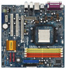
Slots 23 NVIDIA Single Chip (Dual Channel B: DDRII_3, DDRII_4; Orange) 24 Clear CMOS Jumper (CLRCMOS1) 8 DeskExpress Hot Plug Detection Header 25 HDMR Slot (HDMR1) (IR1) 26 Front Panel Audio Header (HD_AUDIO1) 9 Game Port Header (GAME1) 27 HDMI_SPDIF Header (HDMI_SPDIF1) 10 Floppy Connector - ASRock ALiveNF6G-VSTA | User Manual - Page 11
) 10 USB 2.0 Ports (USB23) 11 VGA Port 12 PS/2 Keyboard Port (Purple) 13 PS/2 Mouse Port (Green) * If you use 2-channel speaker, please connect the speaker's plug into "Front Speaker Jack". See the table below for connection details in accordance with the type of speaker you use. TABLE for Audio - ASRock ALiveNF6G-VSTA | User Manual - Page 12
. Before you install or remove any component, ensure that the power is switched off or the power cord is detached from the power supply. Failure to do so may cause severe damage to the motherboard, peripherals, and/or components. 1. Unplug the power cord from the wall socket before touching any - ASRock ALiveNF6G-VSTA | User Manual - Page 13
STEP 1: Lift Up The Socket Lever STEP 2 / STEP 3: STEP 4: Match The CPU Golden Triangle Push Down And Lock To The Socket Corner The Socket Lever 2.2 Installation of CPU Fan and Heatsink After you install the CPU into this motherboard, it is necessary to install a larger heatsink and cooling - ASRock ALiveNF6G-VSTA | User Manual - Page 14
identical DDRII DIMM pair in Dual Channel B (DDRII_3 and DDRII_4; Orange slots; see p.10 No.7), so that Dual Channel Memory Technology can be activated. This motherboard also allows you to install four DDRII DIMMs for dual channel configuration, and please install identical DDRII DIMMs in all four - ASRock ALiveNF6G-VSTA | User Manual - Page 15
Installing a DIMM Please make sure to disconnect power supply before adding or removing break notch break The DIMM only fits in one correct orientation. It will cause permanent damage to the motherboard and the DIMM if you force the DIMM into the slot at incorrect orientation. Step 3. Firmly insert - ASRock ALiveNF6G-VSTA | User Manual - Page 16
slot) is used for PCI Express cards with x16 lane width graphics cards. PCIE2 (PCIE x1 slot) is used for PCI Express cards with x1 lane width cards, such as Gigabit LAN card, SATA2 card, etc. Installing an expansion card Step 1. Before installing the expansion card, please make sure that the power - ASRock ALiveNF6G-VSTA | User Manual - Page 17
If you do not adjust the BIOS setup, the default value of "Share Memory", [Auto], will disable onboard VGA/D-Sub function when the add-on VGA card is inserted to this motherboard. 4. Install the onboard VGA driver to your system. If you have installed the onboard VGA driver already, there is no need - ASRock ALiveNF6G-VSTA | User Manual - Page 18
1_2 2_3 Short pin2, pin3 to enable (see p.10, No. 1) +5V +5VSB +5VSB (standby) for PS/2 or USB wake up events. Note: To select +5VSB, it not clear the CMOS right after you update the BIOS. If you need to clear the CMOS when you just finish updating the BIOS, you must boot up the system first - ASRock ALiveNF6G-VSTA | User Manual - Page 19
the motherboard! • Floppy Connector (33-pin FLOPPY1) (see p.10 No. 10) Pin1 10, No. 16) (SATAII_2: see p.10, No. 22) (SATAII_3: see p.10, No. 14) (SATAII_4: see p.10, No. 13) 3.0 Gb/s data transfer rate. SATAII_4 SATAII_2 SATAII_3 SATAII_1 These four Serial ATAII (SATAII) connectors support - ASRock ALiveNF6G-VSTA | User Manual - Page 20
the Hot Plug detection function for ASRock DeskExpress. This connector allows you to receive stereo audio input from sound sources such as a CD-ROM, DVD-ROM, TV tuner card, or MPEG card. Front Panel Audio Header (9-pin HD_AUDIO1) (see p.10, No. 26) GND PRESENCE# MIC_RET OUT_RET 1 OUT2_L J_SENSE - ASRock ALiveNF6G-VSTA | User Manual - Page 21
fan still can work successfully even without the fan speed control function. If you plan to connect the 3-Pin CPU fan to the CPU fan connector on this motherboard, please connect it to Pin 1-3. Pin 1-3 Connected 3-Pin Fan Installation ATX Power Connector (20-pin ATXPWR1) (see p.10 No. 32) Please - ASRock ALiveNF6G-VSTA | User Manual - Page 22
cable to this header if the Game port bracket is installed. RRXD1 DDTR#1 DDSR#1 CCTS#1 1 RRI#1 RRTS#1 GND TTXD1 DDCD#1 This COM1 header supports a serial port module. 1 GND SPDIFOUT +5V HDMI_SPDIF header, providing SPDIF audio output to HDMI VGA card, allows the system to connect HDMI Digital TV - ASRock ALiveNF6G-VSTA | User Manual - Page 23
VGA card to the PCI Express Graphics slot on this motherboard. For the proper installation of HDMI VGA card, please refer to the installation guide on page 16. Step 2. Connect the black end (A) of HDMI_SPDIF cable to the HDMI_SPDIF header (HDMI_SPDIF1, yellow, see page 10, No. 27) on the motherboard - ASRock ALiveNF6G-VSTA | User Manual - Page 24
Guide Before installing SATAII hard disk to your computer, please carefully read below SATAII hard disk setup guide. Some default setting of SATAII hard disks may not be at SATAII mode, which operate with the best performance. In order to enable SATAII function, please follow the below instruction - ASRock ALiveNF6G-VSTA | User Manual - Page 25
adopts NVIDIA® GeForce 6100 / nForce 430 or GeForce 6150SE / nForce 430 chipset that supports Serial ATA (SATA) / Serial ATAII (SATAII) hard disks and RAID functions. You may install SATA / SATAII hard disks on this motherboard for internal storage devices. This section will guide you to install the - ASRock ALiveNF6G-VSTA | User Manual - Page 26
make sure the SATA / SATAII driver is installed into system properly. The latest SATA / SATAII driver is available on our support website: www.asrock.com 4. Make sure to use the SATA power cable & data cable, which are from our motherboard package. 5. Please follow below instructions step by step to - ASRock ALiveNF6G-VSTA | User Manual - Page 27
cable to (White) to the power supply 1x4-pin cable. the motherboard's SATAII connector. SATA power cable 1x4-pin power connector (White) Step attention, before you process the Hot Unplug: Please do follow below instruction sequence to process the Hot Unplug, improper procedure will cause the SATA - ASRock ALiveNF6G-VSTA | User Manual - Page 28
be auto-detected and listed on the support CD driver page. Please follow the order from up to bottom side to install those required drivers. Therefore, the drivers you install can work properly. 2.14 HDMR Card and Driver Installation If you do not insert HDMR card to this motherboard, and you finish - ASRock ALiveNF6G-VSTA | User Manual - Page 29
refer to the BIOS RAID installation guide in the following path in the Support CD: .. \ RAID Installation Guide STEP 4: Install Windows® 2000 / Windows® XP / Windows® XP-64bit OS on your system. After step1, 2, 3, you can start to install Windows® 2000 / Windows® XP / Windows® XP 64-bit OS - ASRock ALiveNF6G-VSTA | User Manual - Page 30
the instruction to install Windows® VistaTM / Windows® VistaTM 64-bit OS on your system. When you see "Where do you want to install Windows?" page, please insert the ASRock Support CD into your optical drive, and click the "Load Driver" button on the left on the bottom to load the NVIDIA® RAID - ASRock ALiveNF6G-VSTA | User Manual - Page 31
the BIOS SETUP UTILITY to configure your system. The Flash Memory on the motherboard stores the BIOS SETUP UTILITY. You may run the BIOS SETUP off and then back on. Because the BIOS software is constantly being updated, the following BIOS setup screens and descriptions are for reference purpose - ASRock ALiveNF6G-VSTA | User Manual - Page 32
BIOS Version : ALiveNF6G-VSTA BIOS P2.00 Processor Type : AMD Athlon(tm) 64 Processor 3400+ (64bit supported) Processor Speed : 2200 MHz Microcode Update : F7A/3A L1 Cache Size : 128KB L2 Cache Size : 512KB Total Memory DDRII 1 DDRII 2 DDRII 3 DDRII 4 : 512MB with 64MB shared memory Dual-Channel - ASRock ALiveNF6G-VSTA | User Manual - Page 33
may set the configurations for the following items: CPU Configuration, Chipset Configuration, ACPI Configuration, IDE Configuration, PCIPnP Configuration, Floppy Configuration, SuperIO Configuration, and USB Configuration. Main BIOS SETUP UTILITY Advanced H/W Monitor Boot Security Exit Advanced - ASRock ALiveNF6G-VSTA | User Manual - Page 34
3.3.1 CPU Configuration BIOS SETUP UTILITY Advanced CPU Configuration AM2 Boost Overclock Mode CPU Frequency (MHz) PCIE Frequency (MHz) Boot Failure Guard CPU/LDT Spread Spectrum PCIE Spread Spectrum SATA Spread Spectrum Cool' n' Quiet Dual Core Support Processor Maximum Multiplier Processor - ASRock ALiveNF6G-VSTA | User Manual - Page 35
or compatibility issue with some memory modules or power supplies. Please set this item to [Disable] if above issue occurs. Dual Core Support This item will show if you use Dual Core CPU. Configuration optiona: [Enabled], [Disabled]. The default value is [Enabled]. Processor Maximum Multiplier - ASRock ALiveNF6G-VSTA | User Manual - Page 36
Processor Voltage This item will show when "Multiplier/Voltage Change" is set to [Manual]; otherwise, it will be hidden. The range of the value depends on the CPU you adopt on this motherboard. However, for safety and system stability, it is not recommended to adjust the value of this item. Memory - ASRock ALiveNF6G-VSTA | User Manual - Page 37
[Auto]. MA Timing Use this to adjust values for MA timing. Configuration options: [Auto], [2T], [1T]. The default value is [Auto]. Bank Interleaving Interleaving allows memory accesses to be spread out over banks on the same node, or accross nodes, decreasing access contention. 37 - ASRock ALiveNF6G-VSTA | User Manual - Page 38
3.3.2 Chipset Configuration BIOS SETUP UTILITY Advanced Chipset Settings Onboard LAN Onboard HD Audio Front Panel Controller CD-In Share Memory Primary Graphics Adapter [Enabled] [Auto] [Auto] [Enabled] [Auto] [PCI] CPU-NB Link Speed CPU-NB Kink Width DRAM Voltage [Auto] [Auto] [Auto] To set - ASRock ALiveNF6G-VSTA | User Manual - Page 39
BIOS SETUP UTILITY Advanced ACPI Settings Suspend To RAM Repost Video on STR Resume Away Mode Support Video on STR Resume This feature allows you to repost video on STR resume. (STR refers to suspend to RAM.) Away Mode Support Use this item to enable or disable Away Mode support under Windows® XP - ASRock ALiveNF6G-VSTA | User Manual - Page 40
to use this motherboard to submit Windows® VistaTM certification. 3.3.4 IDE Configuration Advanced BIOS SETUP UTILITY IDE HDDs can not be accessed until you finish configuring RAID functions in NVIDIA BIOS / Windows RAID Utility. IDE Device Configuration You may set the IDE configuration for - ASRock ALiveNF6G-VSTA | User Manual - Page 41
Installed]: Select [Not Installed] to disable the use of IDE device. [Auto]: Select [Auto] to automatically detect the hard disk drive. After selecting the hard disk information into BIOS mode for a hard disk > 512 MB under DOS and Windows; for Netware and UNIX user, select [Disabled] to disable - ASRock ALiveNF6G-VSTA | User Manual - Page 42
maximize the IDE hard disk data transfer rate. 3.3.5 PCIPnP Configuration BIOS SETUP UTILITY Advanced Advanced PCI / PnP Settings PCI Latency Timer PCI is recommended to keep the default value unless the installed PCI expansion cards' specifications require other settings. PCI IDE BusMaster Use - ASRock ALiveNF6G-VSTA | User Manual - Page 43
Parallel Port Mode EPP Version ECP Mode DMA Channel Parallel Port IRQ OnBoard Game Port OnBoard MIDI [1.9] [DMA3] [IRQ7] [Enabled] [Disabled] Allow BIOS to Enable or Disable Floppy Controller. +F1 F9 F10 ESC ASRock DeskExpress on this motherboard, please keep this item on [Disabled] option. 43 - ASRock ALiveNF6G-VSTA | User Manual - Page 44
and [1.7]. ECP Mode DMA Channel Use this item to set the ECP mode DMA channel. Configuration options: [DMA0], [ USB Configuration BIOS SETUP UTILITY Advanced USB Configuration USB Controller USB 2.0 Support Legacy USB Support [Enabled] [Enabled] [Disabled] To enable or disable the onboard USB - ASRock ALiveNF6G-VSTA | User Manual - Page 45
the legacy USB support. 3.4 Hardware Health Event Monitoring Screen In this section, it allows you to monitor the status of the hardware on your system, including the parameters of the CPU temperature, motherboard temperature, CPU fan speed, chassis fan speed, and the critical voltage. BIOS SETUP - ASRock ALiveNF6G-VSTA | User Manual - Page 46
General Help F9 Load Defaults F10 Save and Exit ESC Exit v02.54 (C) Copyright 1985-2003, American Megatrends, Inc. 3.5.1 Boot Settings Configuration BIOS SETUP UTILITY Boot Boot Settings Configuration Boot From Network Bootup Num-Lock [Disabled] [On] To enable or disable the boot from network - ASRock ALiveNF6G-VSTA | User Manual - Page 47
user password, you may also clear it. BIOS SETUP UTILITY Main Advanced H/W Monitor Boot Security Exit Security Settings Supervisor Password : Not Installed User Password : Not Installed Change Supervisor Password Change User Password Install or Change the password. Select Screen Select - ASRock ALiveNF6G-VSTA | User Manual - Page 48
and exit setup?" Select [OK] to save the changes and exit the BIOS SETUP UTILITY. Discard Changes and Exit When you select this option, it message, "Discard changes and exit setup?" Select [OK] to exit the BIOS SETUP UTILITY without saving any changes. Discard Changes When you select this option - ASRock ALiveNF6G-VSTA | User Manual - Page 49
4. Software Support 4.1 Install Operating System This motherboard supports various Microsoft® Windows® operating systems: 2000 / XP / XP Media Center / XP 64-bit / VistaTM / VistaTM 64-bit. Because motherboard settings and hardware options vary, use the setup procedures in this chapter for general - ASRock ALiveNF6G-VSTA | User Manual - Page 50
this feature, please make sure to install "AMD Processor Driver" from the "Support CD" first. If you are using Windows® 2000/XP operating system, please follow the instruction below to enable AMD's Cool 'n' QuietTM technology: 1. From the Windows® 2000/XP operating system, click the Start button
-
 1
1 -
 2
2 -
 3
3 -
 4
4 -
 5
5 -
 6
6 -
 7
7 -
8
-
9
-
10
-
11
-
12
-
13
-
14
-
15
-
16
-
17
-
18
-
19
-
20
-
21
-
22
-
23
-
24
-
25
-
26
-
27
-
28
-
29
-
30
-
31
-
32
-
33
-
34
-
35
-
36
-
37
-
38
-
39
-
40
-
41
-
42
-
43
-
44
-
45
-
46
-
47
-
48
-
49
-
50
 |
 |

1
ALiveNF6G-VSTA
User Manual
Version 1.4
Published October 2007
Copyright©2007 ASRock INC. All rights reserved.