ASRock ALiveNF7G-HD720p R2.0 User Manual
ASRock ALiveNF7G-HD720p R2.0 Manual
 |
View all ASRock ALiveNF7G-HD720p R2.0 manuals
Add to My Manuals
Save this manual to your list of manuals |
ASRock ALiveNF7G-HD720p R2.0 manual content summary:
- ASRock ALiveNF7G-HD720p R2.0 | User Manual - Page 1
ALiveNF7G-HD720p User Manual Version 2.0/5.0 Published November 2007 Copyright©2007 ASRock INC. All rights reserved. 1 - ASRock ALiveNF7G-HD720p R2.0 | User Manual - Page 2
purchaser for backup purpose, without written consent of ASRock Inc. Products and corporate names appearing in this manual may or may not be registered trademarks or copyrights USA ONLY The Lithium battery adopted on this motherboard contains Perchlorate, a toxic substance controlled in Perchlorate - ASRock ALiveNF7G-HD720p R2.0 | User Manual - Page 3
Support 10 1.5 720p Blu-ray (BD) / HD-DVD Films Which Pass Our Lab Test . 11 1.6 Motherboard Layout (ALiveNF7G-HD720p R2.0 12 1.7 Motherboard Layout (ALiveNF7G-HD720p R5.0 13 1.8 ASRock Feature and Operation Guide ....... 33 2.14 Driver Installation Guide 35 2.15 Installing Windows® 2000 / XP - ASRock ALiveNF7G-HD720p R2.0 | User Manual - Page 4
2.17 Untied Overclocking Technology 39 3 . BIOS SETUP UTILITY 40 3.1 Introduction 40 3.1.1 BIOS Menu Bar 40 3.1.2 Navigation Keys 41 3.2 56 4 . Software Support 57 4.1 Install Operating System 57 4.2 Support CD Information 57 4.2.1 Running Support CD 57 4.2.2 Drivers Menu 57 4.2.3 Utilities - ASRock ALiveNF7G-HD720p R2.0 | User Manual - Page 5
the model you are using. www.asrock.com/support/index.asp 1.1 Package Contents 1 x ASRock ALiveNF7G-HD720p Motherboard (Micro ATX Form Factor: 9.6-in x 8.6-in, 24.4 cm x 21.8 cm) 1 x ASRock ALiveNF7G-HD720p Quick Installation Guide 2 x ASRock ALiveNF7G-HD720p Support CD 1 x Ultra ATA 66/100/133 - ASRock ALiveNF7G-HD720p R2.0 | User Manual - Page 6
CH Windows® VistaTM Premium Level HD Audio (ALC662 Audio Codec) - Chipset embedded HDMI Audio - Realtek PHY RTL8201CL (ALiveNF7G-HD720p R2.0) - Speed: 10/100 Ethernet (ALiveNF7G-HD720p R2.0) - Gigabit LAN 10/100/1000 Mb/s (ALiveNF7G-HD720p R5.0) - Giga PHY RTL8211B (ALiveNF7G-HD720p R5.0) - Supports - ASRock ALiveNF7G-HD720p R2.0 | User Manual - Page 7
(see CAUTION 12) - 1 x WiFi/E header (see CAUTION 13) - 4Mb AMI BIOS - AMI Legal BIOS - Supports "Plug and Play" - ACPI 1.1 Compliance Wake Up Events - Supports jumperfree - SMBIOS 2.3.1 Support - Drivers, Utilities, AntiVirus Software (Trial Version) - CPU Temperature Sensing - Chassis Temperature - ASRock ALiveNF7G-HD720p R2.0 | User Manual - Page 8
to spray thermal grease between the CPU and the heatsink when you install the PC system. 7. This motherboard supports ASRock AM2 Boost overclocking technology. If you enable this function in the BIOS setup, the memory performance will improve up to 12.5%, but the effect still depends on the AM2 CPU - ASRock ALiveNF7G-HD720p R2.0 | User Manual - Page 9
Setup Guide" on Driver DVI with HDCP * If you use onboard VGA with total system memory size 512MB and plan to submit Windows motherboard, please refer to Premium Discrete requirement at http://www.asrock.com * If the onboard VGA supports DVI, it must also support HDCP function to qualify for Windows - ASRock ALiveNF7G-HD720p R2.0 | User Manual - Page 10
-DVD playback support on this motherboard requires the proper hardware configuration. Please refer to below table for the minimum hardware requirement. CPU VGA Memory Suggested OS AMD Athlon 64X2 5200+ Onboard VGA with DVI-D port Dual Channel DDR2 800, 1GB x 2 Windows® VistaTM or Windows® VistaTM - ASRock ALiveNF7G-HD720p R2.0 | User Manual - Page 11
configuration. Items Configurations CPU AMD Athlon 64X2 5200+ VGA Onboard VGA with DVI-D port Memory Dual Channel DDR2 800, 1GB x 2 OS Windows® VistaTM or Windows® VistaTM 64 Playback Software CyberLink PowerDVD Ultra DVD Player Pioneer BDR-101A / LG GBW-H10N (BD) HP HD100 (HD-DVD) 11 - ASRock ALiveNF7G-HD720p R2.0 | User Manual - Page 12
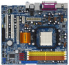
1.6 Motherboard Layout (ALiveNF7G-HD720p R2.0) 12 3 45 21.8cm (8.6-in) 1 PS2_USB_PW1 ATX12V1 67 PS2 -HD720p LAN PHY CD1 1 HD_AUDIO1 AUDIO CODEC PCIE2 PCI1 PCI EXPRESS HDCP CLRCMOS1 1 CMOS BATTERY PCI2 WIFI/E 1 RoHS RAID HDMI_SPDIF1 1 FLOPPY1 DVI COM1 1 4Mb BIOS SPEAKER1 1 IR1 1 - ASRock ALiveNF7G-HD720p R2.0 | User Manual - Page 13
1.7 Motherboard Layout (ALiveNF7G-HD720p R5.0) 12 3 45 21.8cm (8.6-in) 1 PS2_USB_PW1 HD720p PCIE1 NVIDIA GeForce 7050 / nForce 630A MCP Chipset PCIE2 PCI1 PCI EXPRESS HDCP CLRCMOS1 1 CMOS BATTERY PCI2 WIFI/E 1 RoHS RAID HDMI_SPDIF1 1 FLOPPY1 DVI COM1 1 DDRII1066 SATAII 4Mb BIOS - ASRock ALiveNF7G-HD720p R2.0 | User Manual - Page 14
1.8 ASRock 6CH_DVI I/O 1 2 3 4 5 6 11 10 1 PS/2 Mouse Port (Green) 2 Parallel Port 3 RJ-45 Port 4 Line In (Light audio header. Please refer to below steps for the software setting of Multi-Streaming. For Windows® XP: After restarting your computer, you will find "Mixer" tool on your system. - ASRock ALiveNF7G-HD720p R2.0 | User Manual - Page 15
the power is switched off or the power cord is detached from the power supply. Failure to do so may cause severe damage to the motherboard, peripherals, and/or components. 1. Unplug the power cord from the wall socket before touching any component. 2. To avoid damaging the - ASRock ALiveNF7G-HD720p R2.0 | User Manual - Page 16
Socket Lever 2.2 Installation of CPU Fan and Heatsink After you install the CPU into this motherboard, it is necessary to install a larger heatsink and cooling fan to dissipate heat. You 2). For proper installation, please kindly refer to the instruction manuals of the CPU fan and the heatsink. 16 - ASRock ALiveNF7G-HD720p R2.0 | User Manual - Page 17
2.3 Installation of Memory Modules (DIMM) This motherboard provides four 240-pin DDR2 (Double Data Rate 2) DIMM slots, and supports Dual Channel Memory Technology. For dual channel configuration, you always need to install identical (the same brand, speed, size and chip-type) DDR2 DIMM pair - ASRock ALiveNF7G-HD720p R2.0 | User Manual - Page 18
matches the break on the slot. notch break notch break The DIMM only fits in one correct orientation. It will cause permanent damage to the motherboard and the DIMM if you force the DIMM into the slot at incorrect orientation. Step 3. Firmly insert the DIMM into the slot until the retaining - ASRock ALiveNF7G-HD720p R2.0 | User Manual - Page 19
2.4 Expansion Slots (PCI and PCI Express Slots) There are 2 PCI slots and 2 PCI Express slots on this motherboard. PCI slots: PCI slots are used to install expansion cards that have the 32-bit PCI interface. PCIE slots: PCIE1 (PCIE x1 slot) is used - ASRock ALiveNF7G-HD720p R2.0 | User Manual - Page 20
benefits of dual monitor function provided by VGA/DVI-D and VGA/D-Sub ports with this motherboard after your system boots. If you haven't installed onboard VGA driver yet, please install onboard VGA driver from our support CD to your system and restart your computer. Then you can start to use dual - ASRock ALiveNF7G-HD720p R2.0 | User Manual - Page 21
BIOS setup, the default value of "Share Memory", [Auto], will disable VGA/D-Sub function when the add-on VGA card is inserted to this motherboard. 4. Install the onboard VGA driver and the add-on PCI Express VGA card driver one, two, three and four. For Windows® VistaTM / VistaTM 64-bit OS: Right - ASRock ALiveNF7G-HD720p R2.0 | User Manual - Page 22
DVI-D port on this motherboard. To use HDCP function with this motherboard, you need to adopt the monitor that supports HDCP function as well. Therefore, you can enjoy the superior display quality with high-definition HDCP encryption contents. Please refer to below instruction for more details about - ASRock ALiveNF7G-HD720p R2.0 | User Manual - Page 23
sometimes. For Windows® XP / XP 64-bit OS Step 1: Set up BIOS. A. Enter BIOS SETUP UTILITY Advanced screen Chipset Configuration. B. Set the option "OnBoard HDMI HD Audio" to [Auto]. Step 2: Install HDMI audio driver to your system. Install "Onboard HDMI HD Audio Driver" from ASRock Support CD to - ASRock ALiveNF7G-HD720p R2.0 | User Manual - Page 24
and pin3 on CLRCMOS1 for 5 seconds. However, please do not clear the CMOS right after you update the BIOS. If you need to clear the CMOS when you just finish updating the BIOS, you must boot up the system first, and then shut it down before you do the clear-CMOS action - ASRock ALiveNF7G-HD720p R2.0 | User Manual - Page 25
blue end to the motherboard connect the black end to the IDE devices 80-conductor ATA 66/100/133 cable Note: Please refer to the instruction of your IDE 2) SATAII_4 (PORT 3) These four Serial ATAII (SATAII) connectors support SATAII or SATA hard disk for internal storage devices. The current - ASRock ALiveNF7G-HD720p R2.0 | User Manual - Page 26
I/O panel, there are three USB 2.0 headers on this motherboard. Each USB 2.0 header can support two USB 2.0 ports. USB_PWR P-7 P+7 GND DUMMY 1 GND MIC_RET OUT_RET 1 OUT2_L J_SENSE OUT2_R MIC2_R MIC2_L 26 This header supports WiFi+AP function with ASRock WiFi-802.11g or WiFi-802.11n module, an easy - ASRock ALiveNF7G-HD720p R2.0 | User Manual - Page 27
the chassis must support HDA to function correctly. Please follow the instruction in our manual and chassis manual to install your BIOS Setup Utility. Enter Advanced Settings, and then select Chipset Configuration. Set the Front Panel Control option from [Auto] to [Enabled]. F. Enter Windows - ASRock ALiveNF7G-HD720p R2.0 | User Manual - Page 28
provides 4-Pin CPU fan (Quiet Fan) support, the 3-Pin CPU fan still can work successfully even without the fan speed control function. If you plan to connect the 3-Pin CPU fan to the CPU fan connector on this motherboard, please connect it to Pin 1-3. Pin 1-3 Connected 3-Pin Fan Installation - ASRock ALiveNF7G-HD720p R2.0 | User Manual - Page 29
VGA card to this header. HDMI_SPDIF Cable (Optional) C B A Please connect the black end (A) of HDMI_SPDIF cable to the HDMI_SPDIF header on the motherboard. Then connect the white end (B or C) of HDMI_SPDIF cable to the HDMI_SPDIF connector of HDMI VGA card. A. black end +5V SPDIFOUT GND blue - ASRock ALiveNF7G-HD720p R2.0 | User Manual - Page 30
motherboard with a HDMI_SPDIF header. This motherboard motherboard. For the proper installation of HDMI VGA card, please refer to the installation guide manual of HDMI VGA card vendor. Incorrect connection may cause permanent damage to this motherboard , the motherboard and the card user manual for - ASRock ALiveNF7G-HD720p R2.0 | User Manual - Page 31
guide. Some default setting of SATAII hard disks may not be at SATAII mode, which operate with the best performance. In order to enable SATAII function, please follow the below instruction 's website for details: http://www.hitachigst.com/hdd/support/download.htm The above examples are just for your - ASRock ALiveNF7G-HD720p R2.0 | User Manual - Page 32
NVIDIA® GeForce 7050 / nForce 630A MCP chipset that supports Serial ATA (SATA) / Serial ATAII (SATAII) hard disks and RAID functions. You may install SATA / SATAII hard disks on this motherboard for internal storage devices. This section will guide you to install the SATA / SATAII hard disks. STEP - ASRock ALiveNF7G-HD720p R2.0 | User Manual - Page 33
is installed into system properly. The latest SATA / SATAII driver is available on our support website: www.asrock.com 4. Make sure to use the SATA power cable & data cable, which are from our motherboard package. 5. Please follow below instructions step by step to reduce the risk of HDD crash or - ASRock ALiveNF7G-HD720p R2.0 | User Manual - Page 34
cable to (White) to the power supply 1x4-pin cable. the motherboard's SATAII connector. SATA power cable 1x4-pin power connector (White) Step attention, before you process the Hot Unplug: Please do follow below instruction sequence to process the Hot Unplug, improper procedure will cause the SATA - ASRock ALiveNF7G-HD720p R2.0 | User Manual - Page 35
Mode" option to [AHCI]. STEP 2: Make a SATA / SATAII driver diskette. A. Insert the ASRock Support CD into your optical drive to boot your system. (There are two ASRock Support CD in the motherboard gift box pack, please choose the one for Windows® 2000 / XP / XP 64-bit.) B. During POST at - ASRock ALiveNF7G-HD720p R2.0 | User Manual - Page 36
system will start to format the floppy diskette and copy SATA / SATAII drivers into the floppy diskette. STEP 3: Install Windows® 2000 / XP / XP 64-bit OS on your system. After making a SATA / SATAII driver diskette, you can start to install Windows® 2000 / XP / XP 64-bit on your system. At the - ASRock ALiveNF7G-HD720p R2.0 | User Manual - Page 37
" button on the left on the bottom to load the NVIDIA® AHCI drivers. NVIDIA® AHCI drivers are in the following path in our Support CD: (There are two ASRock Support CD in the motherboard gift box pack, please choose the one for Windows® VistaTM / VistaTM 64-bit.) .. \ I386 \ AHCI_Vista (For - ASRock ALiveNF7G-HD720p R2.0 | User Manual - Page 38
the Support CD: .. \ RAID Installation Guide NOTE. Currently, the RAID driver for Windows® 2000 / Windows® XP / Windows® XP 64-bit OS is not ready yet. As long as we get the Windows® 2000 / Windows® XP / Windows® XP 64-bit RAID driver, we will update it to our website in the future. ASRock website - ASRock ALiveNF7G-HD720p R2.0 | User Manual - Page 39
" button on the left on the bottom to load the NVIDIA® RAID drivers. NVIDIA® RAID drivers are in the following path in our Support CD: (There are two ASRock Support CD in the motherboard gift box pack, please choose the one for Windows® VistaTM / VistaTM 64-bit.) .. \ I386 \ RAID_Vista (For - ASRock ALiveNF7G-HD720p R2.0 | User Manual - Page 40
SETUP UTILITY 3.1 Introduction This section explains how to use the BIOS SETUP UTILITY to configure your system. The Flash Memory on the motherboard stores the BIOS SETUP UTILITY. You may run the BIOS SETUP UTILITY when you start up the computer. Please press during the Power-On-Self-Test (POST - ASRock ALiveNF7G-HD720p R2.0 | User Manual - Page 41
SETUP UTILITY Main Advanced H/W Monitor Boot Security Exit System Overview System Time System Date [17:00:09] [Fri 05/11/2007] BIOS Version : ALiveNF7G-HD720p BIOS P1.0 Processor Type : AMD Athlon(tm) 64 Processor 3500+ (64bit) Processor Speed : 2200 MHz Microcode Update : 40FF2/0 L1 Cache Size - ASRock ALiveNF7G-HD720p R2.0 | User Manual - Page 42
malfunction. 3.3.1 CPU Configuration BIOS SETUP UTILITY Advanced CPU Configuration will be left at the rated frequency/voltage. If Manual, multiplier and voltage will be set based on User set this option to [Enabled], you will enable ASRock AM2 Boost function, which will improve the memory - ASRock ALiveNF7G-HD720p R2.0 | User Manual - Page 43
] and [Disabled]. If you install Windows® VistaTM and want to enable this function support the Halt State (C1). The C1 state is supported through the native processor instructions HLT and MWAIT and requires no hardware support default. If it is set to [Manual], you may adjust the value of Processor - ASRock ALiveNF7G-HD720p R2.0 | User Manual - Page 44
BIOS SETUP UTILITY Advanced CPU Configuration AM2 Boost Overclock Mode CPU Frequency ( show when "Multiplier/Voltage Change" is set to [Manual]; otherwise, it will be hidden. The range of the value depends on the CPU you adopt on this motherboard. However, for safety and system stability, it is not - ASRock ALiveNF7G-HD720p R2.0 | User Manual - Page 45
TRAS Use this to adjust TRAS values. Configuration options: [Auto], [5CLK] to [18CLK]. The default value is [Auto]. TRRD Use this to adjust TRRD values. Configuration options: [Auto], [2CLK], [3CLK], [4CLK] and [5CLK]. The default value is [Auto]. TRC Use this to adjust TRC values. Configuration - ASRock ALiveNF7G-HD720p R2.0 | User Manual - Page 46
3.3.2 Chipset Configuration BIOS SETUP UTILITY Advanced Chipset Settings Onboard LAN Onboard HDMI HD Audio Onboard HD Audio Front Panel Share Memory Primary Graphics Adapter CPU-NB Link Speed - ASRock ALiveNF7G-HD720p R2.0 | User Manual - Page 47
ACPI Configuration BIOS SETUP UTILITY Advanced ACPI Settings Suspend To RAM Repost Video on STR Resume Check Ready Bit Away Mode Support Restore on the feature Check Ready Bit. Away Mode Support Use this item to enable or disable Away Mode support under Windows® XP Media Center OS. The default - ASRock ALiveNF7G-HD720p R2.0 | User Manual - Page 48
plan to use this motherboard to submit Windows® VistaTM certification. 3.3.4 IDE Configuration BIOS SETUP UTILITY Advanced HDDs can not be accessed until you finish configuring RAID functions in NVIDIA BIOS / Windows RAID Utility. IDE Device Configuration You may set the IDE configuration for the - ASRock ALiveNF7G-HD720p R2.0 | User Manual - Page 49
BIOS SETUP UTILITY Advanced IDE Master Device Vendor Size LBA Mode Block Mode PIO Mode Async DMA Ultra DMA S.M.A.R.T. :Hard Disk :MAXTOR 6L080J4 :80.0 GB :Supported :16Sectors :4 :MultiWord DMA-2 :Ultra DMA-6 :Supported hard disk > 512 MB under DOS and Windows; for Netware and UNIX user, select [ - ASRock ALiveNF7G-HD720p R2.0 | User Manual - Page 50
], [Enabled]. 32Bit Data Transfer Use this item to enable 32-bit access to maximize the IDE hard disk data transfer rate. 3.3.5 PCIPnP Configuration BIOS SETUP UTILITY Advanced Advanced PCI / PnP Settings PCI Latency Timer PCI IDE BusMaster [32] [Enabled] Value in units of PCI clocks for PCI - ASRock ALiveNF7G-HD720p R2.0 | User Manual - Page 51
3F8 / IRQ4] [Disabled] [378] [ECP + EPP] [1.9] [DMA3] [IRQ7] Allow BIOS to Enable or Disable Floppy Controller. +F1 F9 F10 ESC Select Screen Select Item Change Option and [2E8 / IRQ3]. If you plan to use ASRock DeskExpress on this motherboard, please keep this item on [Disabled] option. 51 - ASRock ALiveNF7G-HD720p R2.0 | User Manual - Page 52
to set the IRQ for the parallel port. Configuration options: [IRQ5] and [IRQ7]. 3.3.8 USB Configuration BIOS SETUP UTILITY Advanced USB Configuration USB Controller USB 2.0 Support Legacy USB Support [Enabled] [Enabled] [Disabled] To enable or disable the onboard USB controllers. +F1 F9 F10 - ASRock ALiveNF7G-HD720p R2.0 | User Manual - Page 53
the status of the hardware on your system, including the parameters of the CPU temperature, motherboard temperature, CPU fan speed, chassis fan speed, and the critical voltage. BIOS SETUP UTILITY Main Advanced H/W Monitor Boot Security Exit Hardware Health Event Monitoring CPU Temperature - ASRock ALiveNF7G-HD720p R2.0 | User Manual - Page 54
F1 General Help F9 Load Defaults F10 Save and Exit ESC Exit v02.54 (C) Copyright 1985-2003, American Megatrends, Inc. 3.5.1 Boot Settings Configuration BIOS SETUP UTILITY Boot Boot Settings Configuration Boot From Onboard LAN Bootup Num-Lock [Disabled] [On] To enable or disable the boot from - ASRock ALiveNF7G-HD720p R2.0 | User Manual - Page 55
you may set or change the supervisor/user password for the system. For the user password, you may also clear it. BIOS SETUP UTILITY Main Advanced H/W Monitor Boot Security Exit Security Settings Supervisor Password : Not Installed User Password : Not Installed Change Supervisor Password - ASRock ALiveNF7G-HD720p R2.0 | User Manual - Page 56
and exit setup?" Select [OK] to save the changes and exit the BIOS SETUP UTILITY. Discard Changes and Exit When you select this option, it message, "Discard changes and exit setup?" Select [OK] to exit the BIOS SETUP UTILITY without saving any changes. Discard Changes When you select this option - ASRock ALiveNF7G-HD720p R2.0 | User Manual - Page 57
install the necessary drivers to activate the devices. 4.2.3 Utilities Menu The Utilities Menu shows the applications software that the motherboard supports. Click on a specific item then follow the installation wizard to install it. 4.2.4 Contact Information If you need to contact ASRock or want to
-
 1
1 -
 2
2 -
 3
3 -
 4
4 -
 5
5 -
 6
6 -
 7
7 -
8
-
9
-
10
-
11
-
12
-
13
-
14
-
15
-
16
-
17
-
18
-
19
-
20
-
21
-
22
-
23
-
24
-
25
-
26
-
27
-
28
-
29
-
30
-
31
-
32
-
33
-
34
-
35
-
36
-
37
-
38
-
39
-
40
-
41
-
42
-
43
-
44
-
45
-
46
-
47
-
48
-
49
-
50
-
51
-
52
-
53
-
54
-
55
-
56
-
57
 |
 |
1
ALiveNF7G-HD720p
User Manual
Version 2.0/5.0
Published November 2007
Copyright©2007 ASRock INC. All rights reserved.