ASRock ALiveSATA2-GLAN User Manual
ASRock ALiveSATA2-GLAN Manual
 |
View all ASRock ALiveSATA2-GLAN manuals
Add to My Manuals
Save this manual to your list of manuals |
ASRock ALiveSATA2-GLAN manual content summary:
- ASRock ALiveSATA2-GLAN | User Manual - Page 1
ALiveSATA2-GLAN User Manual Version 1.4 Published February 2007 Copyright©2007 ASRock INC. All rights reserved. 1 - ASRock ALiveSATA2-GLAN | User Manual - Page 2
purchaser for backup purpose, without written consent of ASRock Inc. Products and corporate names appearing in this manual may or may not be registered trademarks or copyrights USA ONLY The Lithium battery adopted on this motherboard contains Perchlorate, a toxic substance controlled in Perchlorate - ASRock ALiveSATA2-GLAN | User Manual - Page 3
23 2.9 Serial ATA (SATA) / Serial ATAII (SATAII) Hard Disks Installation 24 2.10 Hot Plug and Hot Swap Functions for SATA / SATAII HDDs .... 24 2.11 Driver Installation Guide 25 2.12 Installing Windows® 2000 / XP / XP 64-bit / VistaTM / VistaTM 64-bit With RAID Functions 25 2.12.1 Installing - ASRock ALiveSATA2-GLAN | User Manual - Page 4
3.5 Boot Screen 44 3.5.1 Boot Settings Configuration 45 3.6 Security Screen 45 3.7 Exit Screen 46 4 . Software Support 47 4.1 Install Operating System 47 4.2 Support CD Information 47 4.2.1 Running Support CD 47 4.2.2 Drivers Menu 47 4.2.3 Utilities Menu 47 4.2.4 Contact Information 47 4 - ASRock ALiveSATA2-GLAN | User Manual - Page 5
of this manual occur, the updated version will be available on ASRock website without further notice. You may find the latest VGA cards and CPU support lists on ASRock website as well. ASRock website http://www.asrock.com 1.1 Package Contents 1 x ASRock ALiveSATA2-GLAN Motherboard (ATX Form - ASRock ALiveSATA2-GLAN | User Manual - Page 6
cm x 20.3 cm - Socket AM2 for AMD AthlonTM 64FX / 64X2 / 64 and Sempron processors - AMD LIVE!TM Ready - Supports AMD's Cool 'n' QuietTM Technology - FSB 1000 MHz (2.0 GT/s) - Supports Untied Overclocking Technology (see CAUTION 1) - Supports Hyper-Transport Technology - Northbridge: VIA® K8T890 CF - ASRock ALiveSATA2-GLAN | User Manual - Page 7
panel audio connector - 2 x USB 2.0 headers (support 4 USB 2.0 ports) (see CAUTION 9) - 4Mb AMI BIOS - AMI Legal BIOS - Supports "Plug and Play" - ACPI 1.1 Compliance Wake Up Events - Supports jumperfree - SMBIOS 2.3.1 Support - Drivers, Utilities, AntiVirus Software (Trial Version) - CPU Internal - ASRock ALiveSATA2-GLAN | User Manual - Page 8
. To improve heat dissipation, remember to spray thermal grease between the CPU and the heatsink when you install the PC system. 6. This motherboard supports ASRock AM2 Boost overclocking technology. If you enable this function in the BIOS setup, the memory performance will improve up to 12.5%, but - ASRock ALiveSATA2-GLAN | User Manual - Page 9
system integrators and users who purchase this motherboard and plan to submit Windows® VistaTM Premium 2007 and Basic logo, please follow below table for minimum hardware requirements. CPU Memory VGA Sempron 2800+ 1GB system memory DX9.0 with WDDM Driver with 128bit VGA memory (Premium) with 64bit - ASRock ALiveSATA2-GLAN | User Manual - Page 10
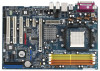
) SOCKET AM2 COM1 34 33 32 31 30 29 28 27 26 25 24 Top: REAR SPK Center: SIDE SPK Bottom: CTR BASS USB 2.0 T: USB2 B: USB3 USB 2.0 T: USB0 B: USB1 Top: RJ-45 CPU_FAN1 Dual Channel DDRII800 Gigabit LAN Super I/O ALiveSATA2-GLAN ATXPWR1 Top: LINE IN Center: FRONT Bottom: MIC IN VIA K8T890 - ASRock ALiveSATA2-GLAN | User Manual - Page 11
Blue) * 7 Front Speaker (Lime) 8 Microphone (Pink) 9 USB 2.0 Ports (USB01) 10 USB 2.0 Ports (USB23) 11 Serial Port: COM1 12 PS/2 Keyboard Port in accordance with the type of speaker you use. TABLE for Audio Output Connection Audio Output Channels Front Speaker Rear Speaker Central / Bass (No. - ASRock ALiveSATA2-GLAN | User Manual - Page 12
2. Installation ALiveSATA2-GLAN is an ATX form factor (12.0-in x 8.0-in, 30.5 cm x 20.3 cm) motherboard. Before you install the motherboard, study the configuration of your chassis to ensure that the motherboard fits into it. Pre-installation Precautions Take note of the following precautions before - ASRock ALiveSATA2-GLAN | User Manual - Page 13
. Make sure that the CPU and the heatsink are securely fastened and in good contact with each other. Then connect the CPU fan to the CPU FAN connector (CPU_FAN1, see Page 10, No. 3). For proper installation, please kindly refer to the instruction manuals of the CPU fan and the heatsink. 13 - ASRock ALiveSATA2-GLAN | User Manual - Page 14
Memory Modules (DIMM) ALiveSATA2-GLAN motherboard provides four 240-pin DDRII (Double Data Rate II) DIMM slots, and supports Dual Channel Memory Technology DDRII_4; Orange slots; see p.10 No.7), so that Dual Channel Memory Technology can be activated. This motherboard also allows you to install four - ASRock ALiveSATA2-GLAN | User Manual - Page 15
matches the break on the slot. notch break notch break The DIMM only fits in one correct orientation. It will cause permanent damage to the motherboard and the DIMM if you force the DIMM into the slot at incorrect orientation. Step 3. Firmly insert the DIMM into the slot until the retaining - ASRock ALiveSATA2-GLAN | User Manual - Page 16
There are 3 PCI slots and 3 PCI Express slots on ALiveSATA2-GLAN motherboard. PCI Slots: PCI slots are used to install expansion cards that you start the installation. Step 2. Remove the system unit cover (if your motherboard is already installed in a chassis). Step 3. Remove the bracket facing the - ASRock ALiveSATA2-GLAN | User Manual - Page 17
cap is placed on these 2 pins. Short Open Jumper Setting PS2_USB_PWR1 1_2 2_3 Short pin2, pin3 to enable (see p.10, No. 1) +5V +5VSB +5VSB (standby) for PS/2 or USB wake up events. Note: To select +5VSB, it requires 2 Amp and higher standby current provided by power supply. Clear - ASRock ALiveSATA2-GLAN | User Manual - Page 18
, see p.10, No. 14) PIN1 IDE1 PIN1 IDE2 connect the blue end to the motherboard connect the black end to the IDE devices 80-conductor ATA 66/100/133 cable Note: If you use only one IDE device on this motherboard, please set the IDE device as "Master". Please refer to the instruction of - ASRock ALiveSATA2-GLAN | User Manual - Page 19
there are two USB 2.0 headers on this motherboard. Each USB 2.0 header can support two USB 2.0 ports. (9-pin USB4_5) (see p.10 No. 11) USB_PWR P-4 P+4 GND DUMMY 1 GND P+5 P-5 USB_PWR Infrared Module Header (5-pin IR1) (see p.10, No. 30) Internal Audio Connector (4-pin CD1) (CD1: see p.10, No. 33 - ASRock ALiveSATA2-GLAN | User Manual - Page 20
cable that allows convenient connection and control of audio devices. 1. High Definition Audio supports Jack Sensing, but the panel wire on the chassis must support HDA to function correctly. Please follow the instruction in our manual and chassis manual to install your system. 2. If you use AC - ASRock ALiveSATA2-GLAN | User Manual - Page 21
motherboard provides 4-Pin CPU fan (Quiet Fan) support, the 3-Pin CPU fan still can work successfully even without the fan speed control function. If you plan to connect the 3-Pin CPU fan to the CPU fan connector on this motherboard HDMI_SPDIF header, providing SPDIF audio output to HDMI VGA card - ASRock ALiveSATA2-GLAN | User Manual - Page 22
motherboard with a HDMI_SPDIF header. This motherboard is equipped with a HDMI_SPDIF header, which provides SPDIF audio guide on page 16. Step 2. Connect the black end (A) of HDMI_SPDIF cable to the HDMI_SPDIF header (HDMI_SPDIF1, yellow, see page 10, No. 23) on the motherboard the motherboard manual - ASRock ALiveSATA2-GLAN | User Manual - Page 23
guide. Some default setting of SATAII hard disks may not be at SATAII mode, which operate with the best performance. In order to enable SATAII function, please follow the below instruction 's website for details: http://www.hitachigst.com/hdd/support/download.htm The above examples are just for your - ASRock ALiveSATA2-GLAN | User Manual - Page 24
supports Serial ATA (SATA) hard disks, and supports RAID functions. You may install SATA / SATAII hard disks on this motherboard for internal storage devices. This section will guide RAID. 2.10 Hot Plug and Hot Swap Functions for SATA / SATAII HDDs ALiveSATA2-GLAN motherboard supports Hot Plug - ASRock ALiveSATA2-GLAN | User Manual - Page 25
1: Set up BIOS. A. Enter BIOS SETUP UTILITY Advanced screen IDE Configuration. B. If you plan to install Windows® 2000 / driver diskette. A. Insert the ASRock Support CD into your optical drive to boot your system. B. During POST at the beginning of system boot-up, press key, and then a window - ASRock ALiveSATA2-GLAN | User Manual - Page 26
proper configuration. Please refer to the BIOS RAID installation guide of the document in the following path in the Support CD: .. \ RAID Installation Guide STEP 4: Install Windows® 2000 / XP / XP 64-bit OS on your system. After making a SATA / SATAII driver diskette and set RAID configuration, you - ASRock ALiveSATA2-GLAN | User Manual - Page 27
instruction to install Windows® VistaTM / VistaTM 64-bit OS on your system. If you plan to install Windows® VistaTM / VistaTM 64-bit on VIA® SATA HDDs, when you see "Where do you want to install Windows?" page, please insert the ASRock Support CD into your optical drive, and click the "Load Driver - ASRock ALiveSATA2-GLAN | User Manual - Page 28
our website for the updates of Windows® VistaTM / VistaTM 64-bit driver and related information in the future. If you want to install Windows® 2000, XP, below steps. STEP 1: Set up BIOS. A. Enter BIOS SETUP UTILITY Advanced screen IDE Configuration. B. If you plan to install Windows® 2000 / XP / XP - ASRock ALiveSATA2-GLAN | User Manual - Page 29
to install Windows® VistaTM / VistaTM 64-bit on your system. 2.14 Untied Overclocking Technology This motherboard supports Untied Overclocking Technology, which means during overclocking, FSB enjoys better margin due to fixed PCI / PCIE buses. You may set "CPU Host Frequency" option of BIOS setup to - ASRock ALiveSATA2-GLAN | User Manual - Page 30
your system. The Flash Memory on the motherboard stores the BIOS SETUP UTILITY. You may run the BIOS SETUP UTILITY when you start up the computer. Please press during the Power-On-Self-Test (POST) to enter the BIOS SETUP UTILITY, otherwise, POST will continue with its test routines. If - ASRock ALiveSATA2-GLAN | User Manual - Page 31
System Overview System Time System Date [17:00:09] [Mon 06/26/2006] BIOS Version : ALiveSATA2-GLAN BIOS P1.0 Processor Type : AMD Athlon(tm) 64 Processor 3500+ (64 bit supported) Processor Speed : 2200 MHz Microcode Update : 10FF0/41 L1 Cache Size : 128KB L2 Cache Size : 1024KB Total Memory - ASRock ALiveSATA2-GLAN | User Manual - Page 32
USB Configuration Configure CPU CPU Configuration BIOS SETUP UTILITY Advanced CPU Configuration AM2 Boost CPU voltage will be left at the rated frequency/voltage. If Manual, multiplier and voltage will be set based on User AM2 Boost If you set this option to [Enabled], you will enable ASRock AM2 - ASRock ALiveSATA2-GLAN | User Manual - Page 33
[Disabled]. If you install Windows® VistaTM and want to Manual], you may adjust the value of Processor Multiplier and Processor Voltage. However, it is recom- mended to keep the default value for system stability. Advanced BIOS SETUP UTILITY BIOS SETUP UTILITY CPU Configuration AM2 Boost CPU - ASRock ALiveSATA2-GLAN | User Manual - Page 34
[Manual]; otherwise, it will be hidden. The range of the value depends on the CPU you adopt on this motherboard. However , for safety and system stability, it is not recommended to adjust the value of this item. Memory Clock This item can be set by the code - ASRock ALiveSATA2-GLAN | User Manual - Page 35
Auto], [0], [5]. 3.3.2 Chipset Configuration BIOS SETUP UTILITY Advanced Chipset Settings DRAM [PCI] [Normal] [Disabled] [Normal] [Enabled] OnBoard HD Audio Front Panel Control [Auto] [Auto] HT Link Speed HT Link free the PCI Bus when the CPU is accessing 8-bit ISA cards. Disable this feature when - ASRock ALiveSATA2-GLAN | User Manual - Page 36
be disabled when PCI Sound Card is plugged. Front Panel Control Select [Auto], [Enabled] or [Disabled] for the onboard HD Audio Front Panel. HT Link Speed You may set the HyperTransport speed as [Auto], [200 MHz], [400 MHz], [600 MHz], [800 MHz], or [1000 MHz]. The - ASRock ALiveSATA2-GLAN | User Manual - Page 37
3.3.3 ACPI Configuration BIOS SETUP UTILITY Advanced ACPI Settings Suspend To RAM Away Mode Support Restore on AC / Power Loss Video on STR Resume" will be hidden. Away Mode Support Use this item to enable or disable Away Mode support under Windows® XP Media Center OS. The default value is [ - ASRock ALiveSATA2-GLAN | User Manual - Page 38
option is [RAID]. Configuration options: [RAID], [non-RAID]. VIA SATA Raid Utility Use this to enable or disable VIA VT8237A SATA Raid BIOS Utility during POST. OnBoard SATAII Controller Use this item to enable or disable onboard PCIE-SATAII controller. The default value of this option is [Enabled - ASRock ALiveSATA2-GLAN | User Manual - Page 39
in the following instruction, which can be applied to 40.0 GB :Supported :16Sectors :4 :MultiWord DMA-2 :Ultra DMA-5 :Supported [Auto] After selecting the hard disk information into BIOS, use a disk utility, such as FDISK hard disk > 512 MB under DOS and Windows; for Netware and UNIX user, select [ - ASRock ALiveSATA2-GLAN | User Manual - Page 40
PIO Mode Use this item to set the PIO mode to enhance hard disk performance by optimizing the hard disk timing. DMA Mode DMA capability allows the improved transfer-speed and data-integrity for compatible IDE devices. S.M.A.R.T. Use this item to enable or disable the S.M.A.R.T. (Self-Monitoring, - ASRock ALiveSATA2-GLAN | User Manual - Page 41
to enable or disable the PCI IDE BusMaster feature. 3.3.6 Floppy Configuration In this section, you may configure the type of your floppy drive. BIOS SETUP UTILITY Advanced Floppy Configuration Floppy A Floppy B [1.44 MB 312"] [Disabled] Select the type of floppy drive connected to the system - ASRock ALiveSATA2-GLAN | User Manual - Page 42
Channel Parallel Port IRQ OnBoard Game Port OnBoard MIDI Port [Enabled] [3F8 / IRQ4] [Disabled] [378] [ECP + EPP] [1.9] [DMA3] [IRQ7] [Enabled] [Disabled] Allow BIOS to Enable or Disable Floppy Controller. +F1 F9 F10 ESC Select Screen Select Item Change Option General Help Load Defaults Save and - ASRock ALiveSATA2-GLAN | User Manual - Page 43
it. Configuration options: [Disabled], [300], and [330]. 3.3.8 USB Configuration BIOS SETUP UTILITY Advanced USB Configuration USB Controller USB 2.0 Support Legacy USB Support [Enabled] [Enabled] [Disabled] To enable or disable the onboard USB controllers. +F1 F9 F10 ESC Select Screen Select - ASRock ALiveSATA2-GLAN | User Manual - Page 44
you to monitor the status of the hardware on your system, including the parameters of the CPU temperature, motherboard temperature, CPU fan speed, chassis fan speed, and the critical voltage. BIOS SETUP UTILITY Main Advanced H/W Monitor Boot Security Exit Hardware Health Event Monitoring - ASRock ALiveSATA2-GLAN | User Manual - Page 45
you may set or change the supervisor/user password for the system. For the user password, you may also clear it. BIOS SETUP UTILITY Main Advanced H/W Monitor Boot Security Exit Security Settings Supervisor Password : Not Installed User Password : Not Installed Change Supervisor Password - ASRock ALiveSATA2-GLAN | User Manual - Page 46
and exit setup?" Select [OK] to save the changes and exit the BIOS SETUP UTILITY. Discard Changes and Exit When you select this option, it message, "Discard changes and exit setup?" Select [OK] to exit the BIOS SETUP UTILITY without saving any changes. Discard Changes When you select this option - ASRock ALiveSATA2-GLAN | User Manual - Page 47
install the necessary drivers to activate the devices. 4.2.3 Utilities Menu The Utilities Menu shows the applications software that the motherboard supports. Click on a specific item then follow the installation wizard to install it. 4.2.4 Contact Information If you need to contact ASRock or want to
-
 1
1 -
 2
2 -
 3
3 -
 4
4 -
 5
5 -
 6
6 -
 7
7 -
8
-
9
-
10
-
11
-
12
-
13
-
14
-
15
-
16
-
17
-
18
-
19
-
20
-
21
-
22
-
23
-
24
-
25
-
26
-
27
-
28
-
29
-
30
-
31
-
32
-
33
-
34
-
35
-
36
-
37
-
38
-
39
-
40
-
41
-
42
-
43
-
44
-
45
-
46
-
47
 |
 |
1
ALiveSATA2-GLAN
User Manual
Version 1.4
Published February 2007
Copyright©2007 ASRock INC. All rights reserved.