ASRock ALiveXFire-eSATA2 Quick Installation Guide
ASRock ALiveXFire-eSATA2 Manual
 |
View all ASRock ALiveXFire-eSATA2 manuals
Add to My Manuals
Save this manual to your list of manuals |
ASRock ALiveXFire-eSATA2 manual content summary:
- ASRock ALiveXFire-eSATA2 | Quick Installation Guide - Page 1
may appear in this guide. With respect to the contents of this guide, ASRock does not provide warranty of any kind, either expressed or implied, including ASRock Website: http://www.asrock.com Published March 2007 Copyright©2007 ASRock INC. All rights reserved. 1 ASRock ALiveXFire-eSATA2 Motherboard - ASRock ALiveXFire-eSATA2 | Quick Installation Guide - Page 2
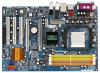
/ XFIRE Power Connector 16 Serial ATAII Connector (SATAII_BLACK (PORT 3)) 35 Internal Audio Connector: CD1 (Black) 17 USB 2.0 Header (USB2_3, Blue) 36 eSATAII Connector (eSATAII_TOP) 18 USB 2.0 Header (USB4_5, Blue) 37 eSATAII Connector (eSATAII_BOTTOM) 2 ASRock ALiveXFire-eSATA2 Motherboard - ASRock ALiveXFire-eSATA2 | Quick Installation Guide - Page 3
"8CH" and then you are allowed to select "Realtek HDA Primary output" to use Rear Speaker, Central/Bass, and Front Speaker, or select "Realtek HDA Audio 2nd output" to use front panel audio. 3 ASRock ALiveXFire-eSATA2 Motherboard English - ASRock ALiveXFire-eSATA2 | Quick Installation Guide - Page 4
of this manual occur, the updated version will be available on ASRock website without further notice. You may find the latest VGA cards and CPU support lists on ASRock website as well. ASRock website http://www.asrock.com 1.1 Package Contents 1 x ASRock ALiveXFire-eSATA2 Motherboard (ATX Form - ASRock ALiveXFire-eSATA2 | Quick Installation Guide - Page 5
Graphics slots for ATITM CrossFireTM (see CAUTION 8) - 1 x PCI Express x1 slot - 3 x PCI slots - 7.1 CH Windows® VistaTM Premium Level HD Audio (ALC888 Audio Codec) - PCIE x1 Gigabit LAN 10/100/1000 Mb/s - Realtek RTL8111B - Supports Wake-On-LAN ASRock 8CH_eSATAII I/O - 1 x PS/2 Mouse Port - 1 x PS - ASRock ALiveXFire-eSATA2 | Quick Installation Guide - Page 6
- Chassis Fan Tachometer - CPU Quiet Fan - Voltage Monitoring: +12V, +5V, +3.3V, Vcore - Microsoft® Windows® 2000 / XP / XP Media Center / XP 64-bit / VistaTM / VistaTM 64-bit compliant (see CAUTION 13) - FCC, CE, Microsoft® WHQL Certificated English 6 ASRock ALiveXFire-eSATA2 Motherboard - ASRock ALiveXFire-eSATA2 | Quick Installation Guide - Page 7
heat dissipation, remember to spray thermal grease between the CPU and the heatsink when you install the PC system. 6. This motherboard supports ASRock AM2 Boost overclocking technology. If you enable this function in the BIOS setup, the memory performance will improve up to 12.5%, but the effect - ASRock ALiveXFire-eSATA2 | Quick Installation Guide - Page 8
.0 with WDDM Driver with 128bit VGA memory (Premium) with 64bit VGA memory (Basic) * After June 1, 2007, all Windows® VistaTM systems are required to meet above minimum hardware requirements in order to qualify for Windows® VistaTM Premium 2007 logo. English 8 ASRock ALiveXFire-eSATA2 Motherboard - ASRock ALiveXFire-eSATA2 | Quick Installation Guide - Page 9
wall socket before touching any component. 2. To avoid damaging the motherboard components due to static electricity, NEVER place your motherboard the motherboard to the chassis, please do not over-tighten the screws! Doing so may damage the motherboard. 9 ASRock ALiveXFire-eSATA2 Motherboard - ASRock ALiveXFire-eSATA2 | Quick Installation Guide - Page 10
are securely fastened and in good contact with each other. Then connect the CPU fan to the CPU FAN connector (CPU_FAN1, see Page 2, No. 3). For proper installation, please kindly refer to the instruction manuals of the CPU fan and the heatsink. English 10 ASRock ALiveXFire-eSATA2 Motherboard - ASRock ALiveXFire-eSATA2 | Quick Installation Guide - Page 11
, installing a pair of memory modules in DDRII_1 and DDRII_3, it is unable to activate the Dual Channel Memory Technology . 4. It is not allowed to install a DDR memory module into DDRII slot; otherwise, this motherboard and DIMM may be damaged. English 11 ASRock ALiveXFire-eSATA2 Motherboard - ASRock ALiveXFire-eSATA2 | Quick Installation Guide - Page 12
damage to the motherboard and the DIMM if you force the DIMM into the slot at incorrect orientation. Step 3. Firmly insert the DIMM into the slot until the retaining clips at both ends fully snap back in place and the DIMM is properly seated. 12 ASRock ALiveXFire-eSATA2 Motherboard English - ASRock ALiveXFire-eSATA2 | Quick Installation Guide - Page 13
before you use ATITM CrossFireTM function. In CrossFireTM mode, the two ATITM graphics cards you install should be from the same GPU family. English 13 ASRock ALiveXFire-eSATA2 Motherboard - ASRock ALiveXFire-eSATA2 | Quick Installation Guide - Page 14
the card before you start the installation. Step 2. Remove the system unit cover (if your motherboard is already installed in a chassis). Step 3. Remove the bracket facing the slot that you intend chassis with screws. Step 6. Replace the system cover. 14 ASRock ALiveXFire-eSATA2 Motherboard English - ASRock ALiveXFire-eSATA2 | Quick Installation Guide - Page 15
another end of the monitor cable to the corresponding port on your monitor. Connect an auxiliary power source from the power supply to the PCI Express x16 graphics card on PCIE3 slot. (Only when your graphics card provides such a power connector.) English 15 ASRock ALiveXFire-eSATA2 Motherboard - ASRock ALiveXFire-eSATA2 | Quick Installation Guide - Page 16
is only supported with Windows® XP with Service Pack 2; it may be supported with other OS in the future, such as Windows® VistaTM. Please check ATITM website for driver updates. What graphics cards work with CrossFireTM? A complete CrossFireTM system requires a CrossFireTM Ready motherboard - ASRock ALiveXFire-eSATA2 | Quick Installation Guide - Page 17
series cards or two Radeon X1600 series cards) on PCIE2/PCIE SWITCH slot and PCIE3 slot to support CrossFireTM. Besides, please connect the monitor cable to the graphics card on PCIE3 slot. Step 5. the graphics card will not work. Ready) graphics card. 17 ASRock ALiveXFire-eSATA2 Motherboard - ASRock ALiveXFire-eSATA2 | Quick Installation Guide - Page 18
the CATALYST Control Center: http://www.microsoft.com/downloads/details.aspx? FamilyId=262D25E3-F589-4842-8157-034D1E7CF3A3&displaylang=en Step 9. Restart your computer. English 18 ASRock ALiveXFire-eSATA2 Motherboard - ASRock ALiveXFire-eSATA2 | Quick Installation Guide - Page 19
Step 10. Install the VGA card drivers to your system, and restart your computer. Then you will find "ATI Catalyst Control Center" on your desktop and is used only for identification or explanation and to the owners' benefit, without intent to infringe. 19 ASRock ALiveXFire-eSATA2 Motherboard English - ASRock ALiveXFire-eSATA2 | Quick Installation Guide - Page 20
for 5 seconds. However, please do not clear the CMOS right after you update the BIOS. If you need to clear the CMOS when you just finish updating the BIOS, you must boot up the system first, and then shut it down before you do the clear-CMOS action. English 20 ASRock ALiveXFire-eSATA2 Motherboard - ASRock ALiveXFire-eSATA2 | Quick Installation Guide - Page 21
eSATAII Connectors These two eSATAII (eSATAII_TOP: see p.2, No. 36) connectors support SATA (eSATAII_BOTTOM: see p.2, No. 37) data cables for external SATAII function. The current eSATAII interface allows up to 3.0 Gb/s data transfer rate. 21 ASRock ALiveXFire-eSATA2 Motherboard English - ASRock ALiveXFire-eSATA2 | Quick Installation Guide - Page 22
two default USB 2.0 ports on the I/O panel, there are four USB 2.0 headers on this motherboard. Each USB 2.0 header can support two USB 2.0 ports. (9-pin USB6_7) (see p.2 No. 19) English (9-pin USB4_5) (see p.2 No. 18) (9-pin USB2_3) (see p.2 No. 17) 22 ASRock ALiveXFire-eSATA2 Motherboard - ASRock ALiveXFire-eSATA2 | Quick Installation Guide - Page 23
"Audio I/O", select "Connector Settings" , choose "Disable front panel jack detection", and save the change by clicking "OK". System Panel Header (9-pin PANEL1) (see p.2 No. 23) This header accommodates several system front panel functions. English 23 ASRock ALiveXFire-eSATA2 Motherboard - ASRock ALiveXFire-eSATA2 | Quick Installation Guide - Page 24
the CPU fan 4 cable to this connector and 3 2 match the black wire to the 1 ground pin. Though this motherboard provides 4-Pin CPU fan (Quiet Fan) support, the 3-Pin CPU fan two graphics cards are plugged to this motherboard at the same time. English 24 ASRock ALiveXFire-eSATA2 Motherboard - ASRock ALiveXFire-eSATA2 | Quick Installation Guide - Page 25
SPDIF audio output to support 2 additional USB 2.0 ports besides the I/O panel. Please connect the blue connector on the cable of this USB bracket to the USB 2.0 header (USB2_3, USB4_5, USB6_7 or USB8_9) and fasten the USB bracket to the chassis with screws. 25 ASRock ALiveXFire-eSATA2 Motherboard - ASRock ALiveXFire-eSATA2 | Quick Installation Guide - Page 26
usage in advance. Connect the HDMI output connector on HDMI VGA card to HDMI device, such as HDTV. Please refer to the user manual of HDTV and HDMI VGA card vendor for detailed connection procedures. Step 5. Install HDMI VGA card driver to your system. 26 ASRock ALiveXFire-eSATA2 Motherboard - ASRock ALiveXFire-eSATA2 | Quick Installation Guide - Page 27
working condition. 2. If you set "SATA Operation Mode" option in BIOS setup to non-RAID mode, Hot Plug function is not supported with eSATAII devices. If you still want to use eSATAII function in . Then the bottom eSATAII port of the I/O shield is enabled. 27 ASRock ALiveXFire-eSATA2 Motherboard - ASRock ALiveXFire-eSATA2 | Quick Installation Guide - Page 28
cable to the red eSATAII connector (eSATAII_BOTTOM) 2. If you plan to install two eSATAII devices to this motherboard, you need to enable both the top and the bottom eSATAII ports of the I/O shield. In so that the eSATAII function will work successfully. 28 ASRock ALiveXFire-eSATA2 Motherboard - ASRock ALiveXFire-eSATA2 | Quick Installation Guide - Page 29
eSATAII port of the I/O shield Comparison between eSATAII and other devices IEEE 1394 USB 2.0 SATA eSATAII/SATAII 400Mb/s 480Mb/s 1.5Gb/s (1500Mb/s) 3.0Gb/s (3000Mb/s) English 29 ASRock ALiveXFire-eSATA2 Motherboard - ASRock ALiveXFire-eSATA2 | Quick Installation Guide - Page 30
.com/hdd/support/download.htm The above examples are just for your reference. For different SATAII hard disk products of different vendors, the jumper pin setting methods may not be the same. Please visit the vendors' website for the updates. 30 ASRock ALiveXFire-eSATA2 Motherboard English - ASRock ALiveXFire-eSATA2 | Quick Installation Guide - Page 31
disks. 2. It is recommended to build RAID 0, RAID 1 or RAID 10 on internal SATA/ SATAII ports. In other words, if SATAII_RED (PORT 1) ATITM Windows RAID. Please refer to RAID Installation Guide in our support CD for detailed operation procedures.) 31 ASRock ALiveXFire-eSATA2 Motherboard English - ASRock ALiveXFire-eSATA2 | Quick Installation Guide - Page 32
first. Then, the drivers compatible to your system can be auto-detected and listed on the support CD driver page. Please follow the order from up to bottom side to install those required drivers. Therefore, the drivers you install can work properly. 32 ASRock ALiveXFire-eSATA2 Motherboard English - ASRock ALiveXFire-eSATA2 | Quick Installation Guide - Page 33
RAID function, you need to check the RAID installation guide in the Support CD for proper configuration. Please refer to the BIOS RAID installation guide part of the document in the following path in the Support CD: .. \ RAID Installation Guide English 33 ASRock ALiveXFire-eSATA2 Motherboard - ASRock ALiveXFire-eSATA2 | Quick Installation Guide - Page 34
Using SATA / SATAII HDDs and eSATAII devices with NCQ and Hot Plug functions" below. NOTE2. AHCI mode is only recommended for Windows® VistaTM / VistaTM 64-bit users. If you install Windows® 2000 / XP / XP 64-bit, it is not suggested to use AHCI mode. 34 ASRock ALiveXFire-eSATA2 Motherboard English - ASRock ALiveXFire-eSATA2 | Quick Installation Guide - Page 35
Hot Plug functions STEP 1: Set up BIOS. A. Enter BIOS SETUP UTILITY Advanced screen IDE Configuration. B. Set the "SATA Operation Mode" option to [non-RAID]. STEP 2: Install Windows® 2000 / Windows® XP / Windows® XP 64-bit OS on your system. English 35 ASRock ALiveXFire-eSATA2 Motherboard - ASRock ALiveXFire-eSATA2 | Quick Installation Guide - Page 36
overclocking, but PCI / PCIE buses are in the fixed mode so that FSB can operate under a more stable overclocking environment. Please refer to the warning on page 7 for the possible overclocking risk before you apply Untied Overclocking Technology. English 36 ASRock ALiveXFire-eSATA2 Motherboard - ASRock ALiveXFire-eSATA2 | Quick Installation Guide - Page 37
about BIOS Setup, please refer to the User Manual (PDF file) contained in the Support CD. 4. Software Support CD information This motherboard supports various Microsoft® Windows® operating " from the "BIN" folder in the Support CD to display the menus. 37 ASRock ALiveXFire-eSATA2 Motherboard English - ASRock ALiveXFire-eSATA2 | Quick Installation Guide - Page 38
38 ASRock ALiveXFire-eSATA2 Motherboard - ASRock ALiveXFire-eSATA2 | Quick Installation Guide - Page 39
™ '' ™ ™ ™ ™ ™ ® 39 ASRock ALiveXFire-eSATA2 Motherboard - ASRock ALiveXFire-eSATA2 | Quick Installation Guide - Page 40
® ® 40 ASRock ALiveXFire-eSATA2 Motherboard - ASRock ALiveXFire-eSATA2 | Quick Installation Guide - Page 41
® ® ® ® 41 ASRock ALiveXFire-eSATA2 Motherboard - ASRock ALiveXFire-eSATA2 | Quick Installation Guide - Page 42
® ® ® ® ® ® ® ® ® 42 ASRock ALiveXFire-eSATA2 Motherboard - ASRock ALiveXFire-eSATA2 | Quick Installation Guide - Page 43
43 ASRock ALiveXFire-eSATA2 Motherboard - ASRock ALiveXFire-eSATA2 | Quick Installation Guide - Page 44
44 ASRock ALiveXFire-eSATA2 Motherboard - ASRock ALiveXFire-eSATA2 | Quick Installation Guide - Page 45
DDRII_1 DDRII_2 DDRII_3 DDRII_4 ( )( )( )( ) (1) - - (2) - - (3) 45 ASRock ALiveXFire-eSATA2 Motherboard - ASRock ALiveXFire-eSATA2 | Quick Installation Guide - Page 46
46 ASRock ALiveXFire-eSATA2 Motherboard - ASRock ALiveXFire-eSATA2 | Quick Installation Guide - Page 47
47 ASRock ALiveXFire-eSATA2 Motherboard - ASRock ALiveXFire-eSATA2 | Quick Installation Guide - Page 48
48 ASRock ALiveXFire-eSATA2 Motherboard - ASRock ALiveXFire-eSATA2 | Quick Installation Guide - Page 49
49 ASRock ALiveXFire-eSATA2 Motherboard - ASRock ALiveXFire-eSATA2 | Quick Installation Guide - Page 50
® ® 50 ASRock ALiveXFire-eSATA2 Motherboard - ASRock ALiveXFire-eSATA2 | Quick Installation Guide - Page 51
51 ASRock ALiveXFire-eSATA2 Motherboard - ASRock ALiveXFire-eSATA2 | Quick Installation Guide - Page 52
® ® 52 ASRock ALiveXFire-eSATA2 Motherboard - ASRock ALiveXFire-eSATA2 | Quick Installation Guide - Page 53
53 ASRock ALiveXFire-eSATA2 Motherboard - ASRock ALiveXFire-eSATA2 | Quick Installation Guide - Page 54
54 ASRock ALiveXFire-eSATA2 Motherboard - ASRock ALiveXFire-eSATA2 | Quick Installation Guide - Page 55
55 ASRock ALiveXFire-eSATA2 Motherboard eSATAII_TOP eSATAII_BOTTOM SATAII_BLUE (PORT 4) SATAII_BLACK (PORT 3) SATAII_ORANGE (PORT 2) SATAII_RED (PORT 1) - ASRock ALiveXFire-eSATA2 | Quick Installation Guide - Page 56
CD1 56 ASRock ALiveXFire-eSATA2 Motherboard - ASRock ALiveXFire-eSATA2 | Quick Installation Guide - Page 57
4 3 2 1 57 ASRock ALiveXFire-eSATA2 Motherboard - ASRock ALiveXFire-eSATA2 | Quick Installation Guide - Page 58
SLI/XFIRE_POWER1 58 ASRock ALiveXFire-eSATA2 Motherboard - ASRock ALiveXFire-eSATA2 | Quick Installation Guide - Page 59
C B A 59 ASRock ALiveXFire-eSATA2 Motherboard - ASRock ALiveXFire-eSATA2 | Quick Installation Guide - Page 60
60 ASRock ALiveXFire-eSATA2 Motherboard - ASRock ALiveXFire-eSATA2 | Quick Installation Guide - Page 61
61 ASRock ALiveXFire-eSATA2 Motherboard - ASRock ALiveXFire-eSATA2 | Quick Installation Guide - Page 62
62 ASRock ALiveXFire-eSATA2 Motherboard - ASRock ALiveXFire-eSATA2 | Quick Installation Guide - Page 63
IEEE 1394 USB 2.0 SATA eSATAII/SATAII 400Mb/s 480Mb/s 1.5Gb/s (1500Mb/s) 3.0Gb/s (3000Mb/s) 63 ASRock ALiveXFire-eSATA2 Motherboard - ASRock ALiveXFire-eSATA2 | Quick Installation Guide - Page 64
64 ASRock ALiveXFire-eSATA2 Motherboard - ASRock ALiveXFire-eSATA2 | Quick Installation Guide - Page 65
TM 65 ASRock ALiveXFire-eSATA2 Motherboard - ASRock ALiveXFire-eSATA2 | Quick Installation Guide - Page 66
TM 66 ASRock ALiveXFire-eSATA2 Motherboard - ASRock ALiveXFire-eSATA2 | Quick Installation Guide - Page 67
® ® ® ® ® ® ® ® ® ® ® 67 ASRock ALiveXFire-eSATA2 Motherboard - ASRock ALiveXFire-eSATA2 | Quick Installation Guide - Page 68
® ® ® ® ® ® ® ® TM ® ® ® ® ® ® ® ® ® ® ® ® ® ® ® ® ® ® ® ® ® ® ® ® ® 68 ASRock ALiveXFire-eSATA2 Motherboard - ASRock ALiveXFire-eSATA2 | Quick Installation Guide - Page 69
® ® ® ® ® ® ® TM ® ® ® ® ® ASRock ALiveXFire-eSATA2 Motherboard ® 69 - ASRock ALiveXFire-eSATA2 | Quick Installation Guide - Page 70
® ® ® ® ® ® 70 ASRock ALiveXFire-eSATA2 Motherboard - ASRock ALiveXFire-eSATA2 | Quick Installation Guide - Page 71
® ® 71 ASRock ALiveXFire-eSATA2 Motherboard - ASRock ALiveXFire-eSATA2 | Quick Installation Guide - Page 72
X O O O X O O O O: X: O O O O 72 ASRock ALiveXFire-eSATA2 Motherboard - ASRock ALiveXFire-eSATA2 | Quick Installation Guide - Page 73
auch auf der ASRock-Website aufgelistet. ASRock-Website: http://www.asrock.com 1.1 Kartoninhalt ASRock ALiveXFire-eSATA2 Motherboard (ATX-Formfaktor: 30.5 cm x 20.8 cm; 12.0 Zoll x 8.2 Zoll) ASRock ALiveXFire-eSATA2 Schnellinstallationsanleitung ASRock ALiveXFire-eSATA2 Support-CD Ein 80-adriges - ASRock ALiveXFire-eSATA2 | Quick Installation Guide - Page 74
(siehe VORSICHT 8) - 1 x PCI Express x1-Steckplätze - 3 x PCI -Steckplätze Audio - 7.1 CH Windows® VistaTM Premium Level HD Audio (ALC888 Audio Codec) LAN - PCIE x1 Gigabit LAN 10/100/1000 Mb/s - Realtek RTL8111B - Unterstützt Wake-On-LAN E/A-Anschlüsse ASRock 8CH_eSATAII I/O an der - ASRock ALiveXFire-eSATA2 | Quick Installation Guide - Page 75
üfter - CPU-Lüftergeräuschdämpfung - Spannungsüberwachung: +12V, +5V, +3.3V, Vcore Betriebssysteme - Unterstützt Microsoft® Windows® 2000 / XP / XP Media Center / XP 64-Bit / VistaTM / VistaTM 64-Bit (siehe VORSICHT 13) Zertifizierungen - FCC, CE, WHQL 75 ASRock ALiveXFire-eSATA2 Motherboard - ASRock ALiveXFire-eSATA2 | Quick Installation Guide - Page 76
Wärmeleitpaste zwischen CPU und Kühlkörper zu sprühen. 6. Dieses Motherboard unterstützt die ASRock AM2 Boost Übertaktungstechnologie. Wenn Sie diese Funktion im BIOS-Setup aktivieren, ATITMGrafikkarten sollten aus derselben GPU-Familie stammen. 76 ASRock ALiveXFire-eSATA2 Motherboard Deutsch - ASRock ALiveXFire-eSATA2 | Quick Installation Guide - Page 77
-Speicher (Premium) mit 64 Bit-VGA-Speicher (Basic) * Nach dem ersten Juni, 2007 sind , all Windows® VistaTM Systems dafür erforderlich, mit der Minimalforderung der obengenannte Hardware übereinzustimmen, um Windows® VistaTM Premium 2007 logo.zu befähigen. 77 ASRock ALiveXFire-eSATA2 Motherboard - ASRock ALiveXFire-eSATA2 | Quick Installation Guide - Page 78
Unterlage, oder zurück in die Tüte, mit der die Komponente geliefert wurde. 5. Wenn Sie das Motherboard mit den Schrauben an dem Computergehäuse befestigen, überziehen Sie bitte die Schrauben nicht! Das Motherboard kann sonst beschädigt werden. Deutsch 78 ASRock ALiveXFire-eSATA2 Motherboard - ASRock ALiveXFire-eSATA2 | Quick Installation Guide - Page 79
sind und einen guten Kontakt zueinander haben. Verbinden Sie dann den CPULüfter mit dem CPU-LÜFTER-Anschluss (CPU_FAN1, siehe Seite 2, Nr. 3). Beziehen Sie sich für eine richtige Installation auf die Handbücher des CPULüfters und des Kühlkörpers. Deutsch 79 ASRock ALiveXFire-eSATA2 Motherboard - ASRock ALiveXFire-eSATA2 | Quick Installation Guide - Page 80
2.3 Installation der Speichermodule (DIMM) Die Motherboards ALiveXFire-eSATA2 bieten vier 240-pol. DDRII (Double Data Rate) DIMM-Steckplä ssig, DDR in einen DDRII Steckplatz zu installieren; andernfalls könnten Motherboard und DIMMs beschädigt werden. Deutsch 80 ASRock ALiveXFire-eSATA2 Motherboard - ASRock ALiveXFire-eSATA2 | Quick Installation Guide - Page 81
in die Steckplätze, so dass die Halteklammern an beiden Enden des Moduls einschnappen und das DIMM-Modul fest an Ort und Stelle sitzt. 81 ASRock ALiveXFire-eSATA2 Motherboard - ASRock ALiveXFire-eSATA2 | Quick Installation Guide - Page 82
, bevor Sie die ATITM CrossFireTM-Funktion verwenden. Im CrossFireTM-Modus funktionieren die zwei von Ihnen installierten ATITMGrafikkarten sollten aus derselben GPU-Familie stammen. Deutsch 82 ASRock ALiveXFire-eSATA2 Motherboard - ASRock ALiveXFire-eSATA2 | Quick Installation Guide - Page 83
drücken Sie sie ohne Gewalt hinein, bis sie den Steckplatz korrekt ausfüllt. Schritt 4: Befestigen Sie die Karte mit der Schraube aus Schritt 2. 83 ASRock ALiveXFire-eSATA2 Motherboard Deutsch - ASRock ALiveXFire-eSATA2 | Quick Installation Guide - Page 84
mit dem entsprechenden Anschluss an Ihrem Monitor. Verbinden Sie eine zusätzliche Stromquelle von der Stromversorgung mit der PCI Express x16-Grafikkarte im PCIE3Steckplatz. (Nur wenn Ihre Grafikkarte über einen derartigen Stromanschluss verfügt.) Deutsch 84 ASRock ALiveXFire-eSATA2 Motherboard - ASRock ALiveXFire-eSATA2 | Quick Installation Guide - Page 85
Windows® XP mit Service Pack 2 unterstützt. Könnte in Zukunft von einem anderen Betriebssystem, z.B. Windows® VistaTM unterstützt werden. Informieren Sie sich auf der ATITMWebsite nach Treiber-Updates den jeweiligen Bedienungsanleitungen zur Grafikkarte nach. 85 ASRock ALiveXFire-eSATA2 Motherboard - ASRock ALiveXFire-eSATA2 | Quick Installation Guide - Page 86
der Radeon X1600-Serie) im PCIE2/PCIE SWITCH- und im PCIE3-Steckplatz installieren. Verbinden Sie auch das Monitorkabel mit der Grafikkarte im PCIE3-Steckplatz. 86 ASRock ALiveXFire-eSATA2 Motherboard Deutsch - ASRock ALiveXFire-eSATA2 | Quick Installation Guide - Page 87
am Monitor. (Wenn Sie zwei Radeon-Standardgrafikkarten (CrossFireTM Ready) in diesem Motherboard installieren, überspringen Sie bitte diesen Schritt.) DVI-DMS-Kabel DMS-Anschluss mit dem Anschluss an der Radeon (CrossFireTM Ready) Grafikkarte. 87 ASRock ALiveXFire-eSATA2 Motherboard Deutsch - ASRock ALiveXFire-eSATA2 | Quick Installation Guide - Page 88
Dienstprogramm herunterzuladen: http://support.ati.com/ics/support/DLRedirect.asp? fileIDExt des Windows® XP service Pack 2 order dessen Nachfolger (Wenn Windows® XP Service Pack 2 oder Schritt 9. Schritt 10. dessen " (CrossFireTM aktivieren) an. 88 ASRock ALiveXFire-eSATA2 Motherboard - ASRock ALiveXFire-eSATA2 | Quick Installation Guide - Page 89
ein eingetragenes Warenzeichen der ATITM Technologies Inc. und wird nur zur Identifizierung oder Erläuterung und zu Gunsten des Inhabers, ohne Rechtverletzungsabsicht, verwendet. C r Deutsch 89 ASRock ALiveXFire-eSATA2 Motherboard - ASRock ALiveXFire-eSATA2 | Quick Installation Guide - Page 90
Sie nicht, den Jumper wieder zu entfernen, nachdem das CMOS gelöscht wurde. Wenn Sie den CMOS-Inhalt gleich nach dem Aktualisieren des BIOS löschen müssen, müssen Sie zuerst das System starten und dann wieder ausschalten, bevor Sie den CMOS-Inhalt löschen. 90 ASRock ALiveXFire-eSATA2 Motherboard - ASRock ALiveXFire-eSATA2 | Quick Installation Guide - Page 91
blau) (39-pin IDE1, siehe S.2, Punkt 9) Blauer Anschluss Schwarzer Anschluss zum Motherboard zur Festplatte 80-adriges ATA 66/100/133-Kabel Hinweis: Details entnehmen Sie bitte 4) SATAII_BLACK (PORT 3) SATAII_ORANGE (PORT 2) SATAII_RED (PORT 1) Deutsch 91 ASRock ALiveXFire-eSATA2 Motherboard - ASRock ALiveXFire-eSATA2 | Quick Installation Guide - Page 92
S.2 - Nr. 19) Zusätzlich zu den beiden üblichen USB 2.0-Ports an den I/O-Anschlüssen befinden sich vier USB 2.0-Anschlussleisten am Motherboard. Pro USB 2.0Anschlussleiste werden zwei USB 2.0-Ports unterstützt. (9-pol. USB4_5) (siehe S.2 - Nr. 18) Deutsch 92 ASRock ALiveXFire-eSATA2 Motherboard - ASRock ALiveXFire-eSATA2 | Quick Installation Guide - Page 93
E. Rufen Sie das BIOS-Setup-Dienstprogramm auf. Audio-Manager aufzurufen. Klicken Sie auf "Audio-E/A", wählen Sie die "Anschlusseinstellungen" , wählen Sie "Erkennung der Frontleistenbuchse deaktivieren" und speichern Sie die Änderung durch Klicken auf "OK". 93 ASRock ALiveXFire-eSATA2 Motherboard - ASRock ALiveXFire-eSATA2 | Quick Installation Guide - Page 94
werden; auch ohne Geschwindigkeitsregulierung. Wenn Sie einen dreipoligen CPU-Lüfter an den CPU-Lüferanschluss dieses Motherboards anschließen möchten, verbinden Sie ihn bitte mit . Andernfalls reicht der Strom nicht aus, das System zu starten. 94 ASRock ALiveXFire-eSATA2 Motherboard Deutsch - ASRock ALiveXFire-eSATA2 | Quick Installation Guide - Page 95
-Kabels mit dem HDMI_SPDIF-Anschluss am Motherboard. Schließen Sie dann das weiße Ende (B oder C) des HDMI_SPDIF-Kabels an den HDMI_SPDIF-Anschluss der HDMI-VGA-Karte an. A. Schwarzes Ende B. Weißes Ende (zweipolig) C. Weißes Ende (dreipolig) Deutsch 95 ASRock ALiveXFire-eSATA2 Motherboard - ASRock ALiveXFire-eSATA2 | Quick Installation Guide - Page 96
des Kabels zum USBBlech mit der USB 2.0Anschlussleiste (USB2_3, USB4_5, USB6_7 oder USB8_9) und befestigen Sie das USBBlech mit Schrauben am Gehäuse. Deutsch 96 ASRock ALiveXFire-eSATA2 Motherboard - ASRock ALiveXFire-eSATA2 | Quick Installation Guide - Page 97
falschen Anschluss: Hier wird versucht, das HDMI_SPDIF-Kabel mit dem Lüfteranschluss der PCI Express-VGA-Karte zu verbinden. Schauen Sie in die Dokumentation Ihrer VGA-Karte und informieren Sie sich schon im Vorfeld über die richtige Nutzung der Anschlüsse. 97 ASRock ALiveXFire-eSATA2 Motherboard - ASRock ALiveXFire-eSATA2 | Quick Installation Guide - Page 98
Handhabung bietet. HINWEIS: 1. Wenn Sie die Option "SATA Operation Mode" (SATA-Betriebsmodus) im BIOS- Setup auf den AHCI- oder den RAID-Modus setzen, wird die Hot Plug-Funktion auf eSATAII -Modus sind auf den Seiten 105 zu 109 angegeben. Deutsch 98 ASRock ALiveXFire-eSATA2 Motherboard - ASRock ALiveXFire-eSATA2 | Quick Installation Guide - Page 99
dem roten eSATAIIAnschluss (eSATAII_BOTTOM). 2. Wenn Sie zwei eSATAII-Geräte mit Ihrem Motherboard verwenden möchten, müssen Sie sowohl den oberen als auch den unteren eSATAII-Anschluss auch der untere eSATAII-Anschluss am Ein-/Ausgabefeld aktiviert. 99 ASRock ALiveXFire-eSATA2 Motherboard Deutsch - ASRock ALiveXFire-eSATA2 | Quick Installation Guide - Page 100
eSATAII-Gerätekabels an das eSATAII-Gerät an. Verbinden Sie das andere Ende des eSATAIIGerätekabels mit dem eSATAII-Anschluss am Ein-/Ausgabefeld. Deutsch 100 ASRock ALiveXFire-eSATA2 Motherboard - ASRock ALiveXFire-eSATA2 | Quick Installation Guide - Page 101
Vergleich von eSATAII- mit anderen Geräten IEEE 1394 USB 2.0 SATA eSATAII/SATAII 400Mb/s 480Mb/s 1.5Gb/s (1500Mb/s) 3.0Gb/s (3000Mb/s) Deutsch ASRock ALiveXFire-eSATA2 Motherboard 101 - ASRock ALiveXFire-eSATA2 | Quick Installation Guide - Page 102
Internetseite von HITACHI finden Sie entsprechende Details: http://www.hitachigst.com/hdd/support/download.htm Die Beispiele oben dienen lediglich Ihrer Referenz. Die Steckbrü änzende Informationen finden Sie auf der Internetseite des Herstellers. Deutsch 102 ASRock ALiveXFire-eSATA2 Motherboard - ASRock ALiveXFire-eSATA2 | Quick Installation Guide - Page 103
RAID (RAID 0, RAID 1 und RAID 10) unterstützt. Sie können mit diesem Motherboard SATA / SATAII-Festplatten als internes Speichermedium verwenden ATITM Windows RAID. Details zur Bedienung finden Sie auf unserer CD in den RAID Installationsanweisungen.) Deutsch ASRock ALiveXFire-eSATA2 Motherboard - ASRock ALiveXFire-eSATA2 | Quick Installation Guide - Page 104
Hot-Plug- und Hot-Swap-Funktion für SATA / SATAIIFestplatten und eSATAII-Geräte Das ALiveXFire-eSATA2-Motherboard unterstützt Hot Plug- und Hot SwapFunktionen für SATA- / SATAII- / eSATAII-Gerä die von Ihnen installierten Treiber richtig arbeiten. Deutsch 104 ASRock ALiveXFire-eSATA2 Motherboard - ASRock ALiveXFire-eSATA2 | Quick Installation Guide - Page 105
Verfügung. Wenn Sie Windows® VistaTM / VistaTM 64-Bit installieren und RAID-Funktionen nutzen wollen, besuchen Sie bitte unsere Internetseite für Updates der Windows® VistaTM / VistaTM 64-Bit und kopiert die SATA / SATAII-Treiber auf die Diskette. ASRock ALiveXFire-eSATA2 Motherboard 105 Deutsch - ASRock ALiveXFire-eSATA2 | Quick Installation Guide - Page 106
vorzunehmen: .. \ RAID Installation Guide HINWEIS 2: Handelt es sich bei Ihrem Betriebssystem um Windows® 2000, installieren Sie den Treiber der Grafikkarte bitte noch vor Installation der "SATA2 Utility" von Ihrer SupportCD auf Ihr System. Deutsch 106 ASRock ALiveXFire-eSATA2 Motherboard - ASRock ALiveXFire-eSATA2 | Quick Installation Guide - Page 107
Windows® 2000 / XP / XP 64-Bit installieren, sollte der AHCI-Modus nicht verwendet werden. Verwendung von SATA / SATAII-Festplatten und eSATAII-Geräten mit NCQ und Hot-Plug-Funktionen SCHRITT 1: Konfigurieren Sie BIOS. A. Rufen Sie im BIOS . Deutsch ASRock ALiveXFire-eSATA2 Motherboard 107 - ASRock ALiveXFire-eSATA2 | Quick Installation Guide - Page 108
Sie in den BIOS RAID-Installationsanweisungen, die Sie auf der CD unter folgendem Pfad finden: .. \ RAID Installation Guide 1. JBOD-Funktion [non-RAID]. SCHRITT 2: Installieren Sie Windows® 2000 / Windows® XP / Windows® XP 64-Bit in Ihrem System. Deutsch 108 ASRock ALiveXFire-eSATA2 Motherboard - ASRock ALiveXFire-eSATA2 | Quick Installation Guide - Page 109
PCI-/PCIE-Busse sind im fixierten Modus, damit der FSB in einer stabileren Übertaktungsumgebung operieren kann. Beziehen Sie sich auf die Warnung vor möglichen Overclocking-Risiken auf Seite 76, bevor Sie die Untied Overclocking-Technologie anwenden. Deutsch ASRock ALiveXFire-eSATA2 Motherboard - ASRock ALiveXFire-eSATA2 | Quick Installation Guide - Page 110
Support-CD, um die Menüs aufzurufen. Das Setup-Programm soll es Ihnen so leicht wie möglich machen. Es ist menügesteuert, d.h. Sie können in den verschiedenen Untermenüs Ihre Auswahl treffen und die Programme werden dann automatisch installiert. Deutsch 110 ASRock ALiveXFire-eSATA2 Motherboard - ASRock ALiveXFire-eSATA2 | Quick Installation Guide - Page 111
la fente de COMMUTATION PCI Express 2/PCI Express, ce qui vous procure une meilleure flexibilité pour choisir les fonctions PCI Express entre une fente PCI Express x16 et deux fentes PCI Express pour ATITM CrossFireTM sans installer de cavaliers. Français ASRock ALiveXFire-eSATA2 Motherboard 111 - ASRock ALiveXFire-eSATA2 | Quick Installation Guide - Page 112
8) - 1 x slot PCI Express x1 - 3 x slots PCI Audio - 7.1 Son haute définition de première qualité CH Windows® VistaTM (codec audio ALC888) LAN - PCIE x1 Gigabit LAN 10/100/1000 Mb/s - Realtek RTL8111B - Support du Wake-On-LAN Panneau arrière ASRock 8CH_eSATAII I/O E/S - 1 x port - ASRock ALiveXFire-eSATA2 | Quick Installation Guide - Page 113
- Détection de la température ambiante de l'UC - Mesure de température de la carte mère - Tachéomètre ventilateur CPU - Tachéomètre ventilateur châssis - Ventilateur silencieux d'unité centrale - Monitoring de la tension: +12V, +5V, +3.3V, Vcore ASRock ALiveXFire-eSATA2 Motherboard 113 Français - ASRock ALiveXFire-eSATA2 | Quick Installation Guide - Page 114
pour conserver la stabilité de votre système. 7. Veuillez retirer la carte de commutation PCI Express de la fente de COMMUTATION PCI Express 2/PCI Express avant d'utiliser la fonction ATITM CrossFireTM. En mode CrossFireTM, les deux cartes graphiques ASRock ALiveXFire-eSATA2 Motherboard Français - ASRock ALiveXFire-eSATA2 | Quick Installation Guide - Page 115
pilote WDDM avec mémoire VGA 128bits (Premium) avec mémoire VGA 64bits (Basic) * Apres Juin 1,2007, tous les Windows® VistaTM systems sont demandes de mettre au dessus de exigence du hardware minimum pour qualifier pour Windows® VistaTM Premium 2007 logo. ASRock ALiveXFire-eSATA2 Motherboard 115 - ASRock ALiveXFire-eSATA2 | Quick Installation Guide - Page 116
, placez-le sur un support antistatique ou dans son sachet d'origine. 5. Lorsque vous placez les vis dans les orifices pour vis pour fixer la carte mère sur le châssis, ne serrez pas trop les vis ! Vous risquez sinon d'endommager la carte mère. Français 116 ASRock ALiveXFire-eSATA2 Motherboard - ASRock ALiveXFire-eSATA2 | Quick Installation Guide - Page 117
autre. Ensuite, connectez le ventilateur du CPU à la prise du VENTILATEUR DU CPU (CPU_FAN1, reportez-vous en page 2, No. 3). Pour une bonne installation, veuillez vous référer aux manuels d'instruction sur le ventilateur du CPU et le dissipateur. Français ASRock ALiveXFire-eSATA2 Motherboard 117 - ASRock ALiveXFire-eSATA2 | Quick Installation Guide - Page 118
modules m émoire [DIMM] La carte mère ALiveXFire-eSATA2 dispose de quatre emplacements DIMM DDRII (Double Data Rate) de 240-broches, et supporte la Technologie de Mémoire à Canal Double. Pour ; la carte mère et les DIMM pourraient être endommagés. Français 118 ASRock ALiveXFire-eSATA2 Motherboard - ASRock ALiveXFire-eSATA2 | Quick Installation Guide - Page 119
emplacement jusqu'à ce que les clips de maintien situés aux deux extrémités se ferment complètement et que le module DIMM soit inséré correctement. ASRock ALiveXFire-eSATA2 Motherboard 119 - ASRock ALiveXFire-eSATA2 | Quick Installation Guide - Page 120
Carte graphique simple * carte de commutation PCI Carte graphique PCI Express x16 Express Cartes graphiques doubles en mode CrossFireTM ** Carte graphique Radeon (compatible CrossFireTM) standard Carte graphique Radeon CrossFireTM Edition Français 120 ASRock ALiveXFire-eSATA2 Motherboard - ASRock ALiveXFire-eSATA2 | Quick Installation Guide - Page 121
PCI Express x16 installée sur la fente PCI Express 3 fonctionnant à la bande passante PCI Express x16, veuillez vous assurer que la carte de commutation PCI Express est installée sur la fente de COMMUTATION PCI Express 2/PCI Express aide d'une vis. Français ASRock ALiveXFire-eSATA2 Motherboard 121 - ASRock ALiveXFire-eSATA2 | Quick Installation Guide - Page 122
correspondant à votre moniteur. Connectez une source auxiliaire depuis l'alimentation électrique vers la carte graphique PCI Express x16 sur la fente PCI Express 3. (quand votre carte graphique comporte une telle prise d'alimentation seulement) Français 122 ASRock ALiveXFire-eSATA2 Motherboard - ASRock ALiveXFire-eSATA2 | Quick Installation Guide - Page 123
supporte la fonction CrossFireTM. La technologie CrossFireTM propose les moyens les plus avantageux disponibles en combinant plusieurs CPU actuellement compatible uniquement avec Windows® XP avec le Service Pack 2; elles peuvent guide d'installation détaillé. ASRock ALiveXFire-eSATA2 Motherboard 123 - ASRock ALiveXFire-eSATA2 | Quick Installation Guide - Page 124
cartes de série Radeon X1600) sur la fente de COMMUTATION PCI Express 2/PCI Express et la fente PCI Express 3 pour la prise en charge de CrossFireTM. De plus, veuillez brancher le câble du moniteur à la carte graphique sur la fente PCI Express 3. 124 ASRock ALiveXFire-eSATA2 Motherboard Français - ASRock ALiveXFire-eSATA2 | Quick Installation Guide - Page 125
de la carte graphique CrossFireTM Edition et la troisième extrémité sur le connecteur DVI de la carte graphique Radeon (Compatible CrossFireTM) standard compatible. ASRock ALiveXFire-eSATA2 Motherboard 125 Français - ASRock ALiveXFire-eSATA2 | Quick Installation Guide - Page 126
10. Installez les pilotes requis sur votre système. Veuillez visiter les sites web ci-dessous pour installer les pilotes recommandés par ATITM: A. ATITM recommande d'installer Windows® XP Service "ATI Catalyst Control Center" sur votre bureau. Français 126 ASRock ALiveXFire-eSATA2 Motherboard - ASRock ALiveXFire-eSATA2 | Quick Installation Guide - Page 127
Express, vous pouvez facilement jouir des avantages de la caractéristique de l'affichage Surround. Pour les instructions détaillées, veuillez vous reporter au document qui se trouve sur le chemin suivant dans le CD d'assistance : ..\ Surround Display Information ASRock ALiveXFire-eSATA2 Motherboard - ASRock ALiveXFire-eSATA2 | Quick Installation Guide - Page 128
après avoir mis le BIOS à jour. Si vous avez besoin d'effacer la CMOS lorsque vous avez fini de mettre le BIOS à jour, vous devez d'abord initialiser le système, puis le mettre hors tension avant de procéder à l'opération d'effacement de la CMOS. Français 128 ASRock ALiveXFire-eSATA2 Motherboard - ASRock ALiveXFire-eSATA2 | Quick Installation Guide - Page 129
le disque dur Câble ATA 66/100/133 80 conducteurs Note: Veuillez vous reporter aux instructions du fabricant de votre IDE périphérique pour les détails. Connecteurs Série ATAII ( SATAII_BLACK (PORT 3) SATAII_ORANGE (PORT 2) SATAII_RED (PORT 1) Français ASRock ALiveXFire-eSATA2 Motherboard 129 - ASRock ALiveXFire-eSATA2 | Quick Installation Guide - Page 130
cette carte mère. Chaque embase USB 2.0 peut prendre en charge 2 ports USB 2.0. (USB6_7 br.9) (voir p.2 No. 19) (USB4_5 br.9) (voir p.2 No. 18) Français 130 ASRock ALiveXFire-eSATA2 Motherboard - ASRock ALiveXFire-eSATA2 | Quick Installation Guide - Page 131
entrer dans le Gestionnaire audio Realtek HD. Cliquer sur « E/S audio», sélectionner « Paramètres du connecteur » , choisir « Désactiver la détection de la prise du panneau de commande » et sauvegarder les changements en cliquant sur « OK ». ASRock ALiveXFire-eSATA2 Motherboard 131 Français - ASRock ALiveXFire-eSATA2 | Quick Installation Guide - Page 132
broche de terre. ien que cette carte mère offre un support de (Ventilateur silencieux) ventilateur de CPU à 4 broches , le ventilateur de CPU à 3 broches peut bien fonctionner même sans la fonction il ne sera pas possible de 132 mettre sous tension. ASRock ALiveXFire-eSATA2 Motherboard Français - ASRock ALiveXFire-eSATA2 | Quick Installation Guide - Page 133
jeux sur ce connecteur si le support pour port jeux est installée. Connecteur HDMI_SPDIF Connecteur HDMI_SPDIF, (HDMI_SPDIF1 3-pin) fournissant une sortie audio (voir p.2 No. 29) SPDIF é blanche (2 briches) C. extrémité blanche (3 briches) ASRock ALiveXFire-eSATA2 Motherboard 133 Français - ASRock ALiveXFire-eSATA2 | Quick Installation Guide - Page 134
Support USB Cette console USB peut prendre en charge 2 ports USB 2.0 supplémentaires à côté du panneau E/S. Veuillez connecter le connecteur bleu au câ USB 2.0 (USB2_3, USB4_5, USB 6_7 or USB8_9) et attachez la console USB au châssis avec des vis. Français 134 ASRock ALiveXFire-eSATA2 Motherboard - ASRock ALiveXFire-eSATA2 | Quick Installation Guide - Page 135
. Par exemple, cette image montre le mauvais exemple de connexion du câble HDMI_SPDIF au connecteur du ventilateur de la carte VGA PCI Express. Veuillez vous reporter au préalable au manuel de l'utilisateur de la carte VGA pour l'utilisation du connecteur. ASRock ALiveXFire-eSATA2 Motherboard 135 - ASRock ALiveXFire-eSATA2 | Quick Installation Guide - Page 136
HDMI pour obtenir les procédures de connexion détaillées. Etape 5. Installez les pilotes de la carte VGA HDMI à votre système. Français 136 ASRock ALiveXFire-eSATA2 Motherboard - ASRock ALiveXFire-eSATA2 | Quick Installation Guide - Page 137
vous réglez l'option «SATA Operation Mode» « Mode de fonctionnement SATA » dans les paramètres du BIOS sur le mode non-RAID, la fonction de connexion à chaud n'est pas prise en charge avec les eSATAII inférieur du blindage entrée/sortie est alors activé. ASRock ALiveXFire-eSATA2 Motherboard 137 - ASRock ALiveXFire-eSATA2 | Quick Installation Guide - Page 138
) ORANGE (orange) (PORT 2)) Veuillez veiller à connecter correctement les connecteurs SATAII et eSATAII avec la couleur correspondante de sorte que la fonction eSATAII fonctionne parfaitement. 138 ASRock ALiveXFire-eSATA2 Motherboard - ASRock ALiveXFire-eSATA2 | Quick Installation Guide - Page 139
blindage entrée/sortie. Comparaison entre eSATAII et les autres périphériques IEEE 1394 USB 2.0 SATA eSATAII/SATAII 400Mb/s 480Mb/s 1.5Gb/s (1500Mb/s) 3.0Gb/s (3000Mb/s) Français ASRock ALiveXFire-eSATA2 Motherboard 139 - ASRock ALiveXFire-eSATA2 | Quick Installation Guide - Page 140
veuillez lire attentivement le présent guide d'installation du disque dur SATAII. la fonction SATAII, veuillez suivre les instructions ci-dessous avec les différents de détails. http://www.hitachigst.com/hdd/support/download.htm Les exemples donnés précédemment ne ASRock ALiveXFire-eSATA2 Motherboard - ASRock ALiveXFire-eSATA2 | Quick Installation Guide - Page 141
et les fonctions RAID (RAID 0, RAID 1 et RAID 10). Vous pouvez installer les disques durs SATA / SATAII sur cette Windows RAID. Veuillez vous référer au guide d'installation de RAID dans notre CD d'assistance pour connaître les détails de la procédure) Français ASRock ALiveXFire-eSATA2 Motherboard - ASRock ALiveXFire-eSATA2 | Quick Installation Guide - Page 142
ALiveXFire-eSATA2 gère les fonctions Hot Plug et Hot Swap pour les périphériques SATA / SATAII / eSATAII en mode RAID / AHCI. Le jeu de puces de pont sud ATITM SB600 offre un support de disque dur SATAII. 2.15 Guide d'installation des pilotes Pour installer les ASRock ALiveXFire-eSATA2 Motherboard - ASRock ALiveXFire-eSATA2 | Quick Installation Guide - Page 143
utilisateurs de Windows® VistaTM / VistaTM 64-bit maintenant. Si vous installez Windows® VistaTM BIOS. A. Entrez dans UTILITAIRE DE CONFIGURATION BIOS l'écran le message "Generate Serial ATA driver diskette [Y/N]?" (Voulez-vous générer une disquette ASRock ALiveXFire-eSATA2 Motherboard 143 Français - ASRock ALiveXFire-eSATA2 | Quick Installation Guide - Page 144
du CD Support: .. \ RAID Installation Guide REMARQUE2: Si votre système d'exploitation est Windows® 2000, veuillez installer le pilote de la carte graphique avant d'installer l'« Utilitaire SATA2 » depuis notre CD d'assistance sur votre système. Français 144 ASRock ALiveXFire-eSATA2 Motherboard - ASRock ALiveXFire-eSATA2 | Quick Installation Guide - Page 145
Windows® 2000 / XP / XP 64-bit, il n'est pas conseillé d'utiliser le mode AHCI. Utilisation des disques durs SATA / SATAII et des appareils eSATAII avec NCQ et les fonctions de connexion à chaud ETAP 1: Configurez le BIOS 2, section 2.16, page 143. Français ASRock ALiveXFire-eSATA2 Motherboard 145 - ASRock ALiveXFire-eSATA2 | Quick Installation Guide - Page 146
BIOS écran Avancé Configuration IDE. B. Réglez l'option "SATA Operation Mode"« Mode de fonctionnement SATA » sur [non-RAID]. ETAPE 2: Installer le système d'exploitation Windows® 2000 / Windows® XP / Windows® XP 64-bit sur votre système. Français 146 ASRock ALiveXFire-eSATA2 Motherboard - ASRock ALiveXFire-eSATA2 | Quick Installation Guide - Page 147
mémoire puisse être opéré dans un environnement de surcadençage plus stable. Veuillez vous reporter à l'avertissement en page 114 pour connaître les risques liés à l'overclocking avant d'appliquer la technologie Untied Overclocking. Français ASRock ALiveXFire-eSATA2 Motherboard 147 - ASRock ALiveXFire-eSATA2 | Quick Installation Guide - Page 148
sur le BIOS, veuillez consulter le Guide de l'utilisateur (fichier PDF) dans le CD technique. 4. Informations sur le CD de support Cette carte mère supporte divers systèmes d'exploitation Microsoft® Windows®: 2000 dessus pour afficher les menus. Français 148 ASRock ALiveXFire-eSATA2 Motherboard - ASRock ALiveXFire-eSATA2 | Quick Installation Guide - Page 149
e gli elenchi di CPU supportate. ASRock website http://www.asrock.com 1.1 Contenuto della confezione Scheda madre ASRock ALiveXFire-eSATA2 (ATX Form Factor: 12.0-in x 8.2-in, 30.5 cm x 20.8 cm) Guida di installazione rapida ASRock ALiveXFire-eSATA2 CD di supporto ASRock ALiveXFire-eSATA2 Un cavo IDE - ASRock ALiveXFire-eSATA2 | Quick Installation Guide - Page 150
alloggi PCI Express Graphics per ATITM CrossFireTM (vedi ATTENZIONE 8) - 1 x slot PCI Express x1 - 3 x slot PCI Audio - 7.1 Audio HD CH Windows® VistaTM Premium Level (ALC888 Audio Codec) LAN - PCIE x1 Gigabit LAN 10/100/1000 Mb/s - Realtek RTL8111B - Supporta Wake-On-LAN Pannello ASRock - ASRock ALiveXFire-eSATA2 | Quick Installation Guide - Page 151
- Rilevamento temperatura ambiente CPU - Sensore temperatura scheda madre - Indicatore di velocità per la ventola del processore - Indicatore di velocità per la ventola di raffreddamento - Ventola CPU silenziosa - Voltaggio: +12V, +5V, +3.3V, Vcore ASRock ALiveXFire-eSATA2 Motherboard 151 Italiano - ASRock ALiveXFire-eSATA2 | Quick Installation Guide - Page 152
a 4GB per l'accantonamento riservato all'uso del sistema sotto Windows® XP e Windows® VistaTM. Per Windows® XP 64-bit e Windows® VistaTM 64-bit con CPU 64-bit, non c'è tale limitazione. 4. Anche se questa motherboard offre il controllo stepless, non si consiglia di effettuare l'overclocking. L'uso - ASRock ALiveXFire-eSATA2 | Quick Installation Guide - Page 153
PCI Express driver WDDM Con memoria VGA 128bit (Premium) Con memoria VGA 64bit (Basic) * Dopo il 1 Giugno 2007, tutti i sistemi Windows® VistaTM vengono richiesti di essere in accordo ai requisiti minimi del sistema per Windows® VistaTM Premium 2007 logo. ASRock ALiveXFire-eSATA2 Motherboard - ASRock ALiveXFire-eSATA2 | Quick Installation Guide - Page 154
. 5. Nell'usare i giraviti per fissare la scheda madre al telaio non serrare eccessivamente le viti! Altrimenti si rischia di danneggiare la scheda madre. Italiano 154 ASRock ALiveXFire-eSATA2 Motherboard - ASRock ALiveXFire-eSATA2 | Quick Installation Guide - Page 155
i due. Quindi collegare la ventolina CPU al connettore CPU FAN (CPU_FAN1, fare riferimento a pagina 2, Numero 3). Per eseguire un'installazione appropriata, fare riferimento al manuale d'istruzioni della ventolina CPU e del dispersore di calore. Italiano ASRock ALiveXFire-eSATA2 Motherboard 155 - ASRock ALiveXFire-eSATA2 | Quick Installation Guide - Page 156
ad esempio se si installa una coppia di moduli di memoria su DDRII_1 e DDII_3, è impossibile attivare la tecnologia Dual Channel Memory. 4. Non è consentito installare la DDR nello slot DDRII, altrimenti si possono danneggiare questa scheda madre e la DIMM. 156 ASRock ALiveXFire-eSATA2 Motherboard - ASRock ALiveXFire-eSATA2 | Quick Installation Guide - Page 157
la DIMM nello slot fino a far scattare completamente in posizione i fermagli di ritegno alle due estremità e fino ad installare correttamente la DIMM nella sua sede. ASRock ALiveXFire-eSATA2 Motherboard 157 - ASRock ALiveXFire-eSATA2 | Quick Installation Guide - Page 158
Express) Sulla scheda madre ALiveXFire-eSATA2 c'è 3 slot PCI ed 3 slot PCI Express. Slot PCI: Sono utilizzati per installare schede di espansione con Interfaccia PCI a 32-bit. Slot PCI Express: L'alloggio PCIE1 (1 alloggio PCI Express) è usato per schede PCI Express 1 Lane, come schede Gigabit LAN - ASRock ALiveXFire-eSATA2 | Quick Installation Guide - Page 159
della scheda con lo slot e premere con decisione finché la scheda è completamente inserita nello slot. Step 4. Agganciare la scheda allo chassis con le viti. Italiano ASRock ALiveXFire-eSATA2 Motherboard 159 - ASRock ALiveXFire-eSATA2 | Quick Installation Guide - Page 160
alla porta corrispondente sul monitor. Collegare una sorgente ausiliaria d'alimentazione dall'alimentatore alla scheda grafica PCI Express x16 nell'alloggio PCIE3. (Solo quando la scheda grafica è dotata di tale connettore d'alimentazione.) Italiano 160 ASRock ALiveXFire-eSATA2 Motherboard - ASRock ALiveXFire-eSATA2 | Quick Installation Guide - Page 161
Windows® XP con Service Pack 2; in futuro potrebbe essere supportato da altri sistemi operativi, come Windows® VistaTM. Visitare il sito ATITM per gli aggiornamenti dei driver al manuale della scheda video ATITM per una guida dettagliata all'installazione. ASRock ALiveXFire-eSATA2 Motherboard 161 - ASRock ALiveXFire-eSATA2 | Quick Installation Guide - Page 162
PCIE2/PCIE SWITCH e nell'alloggio PCIE3 per supportare CrossFireTM. Inoltre, collegare una estremità del cavo del monitor alla scheda grafica nell'alloggio PCIE3. Italiano 162 ASRock ALiveXFire-eSATA2 Motherboard - ASRock ALiveXFire-eSATA2 | Quick Installation Guide - Page 163
monitor, un'altra estremità al connettore DMS di una delle schede CrossFireTM Edition, e l'altra estremità al connettore DVI della scheda compatibile standard Radeon (CrossFireTM Ready). ASRock ALiveXFire-eSATA2 Motherboard 163 Italiano - ASRock ALiveXFire-eSATA2 | Quick Installation Guide - Page 164
&displaylang=en Riavviare il computer. Installare i driver scheda VGA sul sistema e riavviare il computer. Quindi sul desktop si troverà l'icona "ATI Catalyst Control Center". Sul desktop si troverà l'icona "ATI Catalyst Control Center". Italiano 164 ASRock ALiveXFire-eSATA2 Motherboard - ASRock ALiveXFire-eSATA2 | Quick Installation Guide - Page 165
documento è un marchio registrato della ATITM Technologies Inc., ed è usato solamente a scopo identificativo o esplicativo a beneficio del proprietario, senza alcuna intenzione di violare i diritti d'autore. Italiano ASRock ALiveXFire-eSATA2 Motherboard 165 - ASRock ALiveXFire-eSATA2 | Quick Installation Guide - Page 166
PCI Express PS/2 o USB wake up events. Nota: BIOS. Se è necessario cancellare la CMOS una volta completato l'aggiornamento del BIOS, è necessario riavviare prima il sistema, e poi spegnerlo prima di procedere alla cancellazione della CMOS. Italiano 166 ASRock ALiveXFire-eSATA2 Motherboard - ASRock ALiveXFire-eSATA2 | Quick Installation Guide - Page 167
supportare periferiche eSATAII. Si prega di consultare "Introduzione all'interfaccia SATAII Interface" a pagina 174 per ulteriori informazioni sulle procedure di installazione di eSATAII ed eSATAII. ASRock ALiveXFire-eSATA2 Motherboard 167 - ASRock ALiveXFire-eSATA2 | Quick Installation Guide - Page 168
2.0 predefinite nel pannello I/O, la scheda madre dispone di quattro intestazioni USB 2.0. Ciascuna intestazione USB 2.0 supporta due porte USB 2.0. (9-pin USB4_5) (vedi p.2 No. 18) Italiano 168 ASRock ALiveXFire-eSATA2 Motherboard - ASRock ALiveXFire-eSATA2 | Quick Installation Guide - Page 169
della barra delle applicazioni per entrare su Realtek HD Audio Manager. Fare clic su "Audio I/O", selezionare "Impostazioni connettore" , scegliere "Disattiva rilevazione presa pannello anteriore" e salvare la modifica facendo clic su "OK". ASRock ALiveXFire-eSATA2 Motherboard 169 Italiano - ASRock ALiveXFire-eSATA2 | Quick Installation Guide - Page 170
1 terra. Sebbene la presente scheda madre disponga di un supporto per ventola CPU a 4 piedini (ventola silenziosa), la ventola CPU a 3 piedini è in grado di funzionare anche senza la funzione di controllo In caso contrario l'unità non si avvia. Italiano 170 ASRock ALiveXFire-eSATA2 Motherboard - ASRock ALiveXFire-eSATA2 | Quick Installation Guide - Page 171
Nr. 29) Cavo HDMI_SPDIF (opzionale) C B A Header HDMI_SPDIF, con uscita audio SPDIF su scheda HDMI VGA, consente al sistema di collegare dispositivi per TV digitale HDMI A. estremità nera B. estremità bianca (2 pin) C. estremità bianca (3 pin) Italiano ASRock ALiveXFire-eSATA2 Motherboard 171 - ASRock ALiveXFire-eSATA2 | Quick Installation Guide - Page 172
connettore blu del cavo del bracket USB all'intestazione USB 2.0 (USB2_3, USB4_5, USB6_7 o USB8_9) e fissare il bracket USB al telao con le viti. Italiano 172 ASRock ALiveXFire-eSATA2 Motherboard - ASRock ALiveXFire-eSATA2 | Quick Installation Guide - Page 173
. Punto 4. Collegare il connettore di uscita HDMI al dispositivo HDMI, ad esempio HDTV. Consultare il manuale dell'utente di HDTV e della scheda HDMI VGA per il collegamento dettagliato. Punto 5. Installare il driver della scheda HDMI VGA nel sistema. ASRock ALiveXFire-eSATA2 Motherboard 173 - ASRock ALiveXFire-eSATA2 | Quick Installation Guide - Page 174
Se si imposta l'opzione "SATA Operation Mode" (Modalità operativa SATA) del BIOS sulla modalità non-RAID, non è supportata la funzione Hot Plug (Collegamento a eSATAII? SATAII_RED (PORT 1) e SATAII_ORANGE (PORT 2) eSATAII_TOP e eSATAII_BOTTOM Italiano 174 ASRock ALiveXFire-eSATA2 Motherboard - ASRock ALiveXFire-eSATA2 | Quick Installation Guide - Page 175
connettori SATAII rosso (SATAII_ RED(rossa) (PORT 1)) ed arancione (SATAII_ORANGE (arancione) (PORT 2)) Collegare i cavi dati SATA ai connettori eSATAII rosso (eSATAII_ BOTTOM) ed arancione (eSATAII_TOP) ASRock ALiveXFire-eSATA2 Motherboard 175 - ASRock ALiveXFire-eSATA2 | Quick Installation Guide - Page 176
alla porta eSATAII dello schermo I/O Confronto fra eSATAII ed altre periferiche IEEE 1394 USB 2.0 SATA eSATAII/SATAII 400Mb/s 480Mb/s 1.5Gb/s (1500Mb/s) 3.0Gb/s (3000Mb/s) Italiano 176 ASRock ALiveXFire-eSATA2 Motherboard - ASRock ALiveXFire-eSATA2 | Quick Installation Guide - Page 177
support/download.htm Gli esempi di cui sopra sono solo per riferimento. Per dischi rigidi SATAII di diversi produttori, i metodi di impostazione dei pin del jumper possono non essere gli stessi. Visitare i siti web dei produttori per gli aggiornamenti. Italiano ASRock ALiveXFire-eSATA2 Motherboard - ASRock ALiveXFire-eSATA2 | Quick Installation Guide - Page 178
(SATAII) e le funzioni RAID (RAID 0, RAID 1 e RAID 10). E possibile installare su questa scheda madre i dischi rigidi SATA / SATAII Windows RAID. Per ulteriori procedure dettagliate, consultare la guida all'installazione RAID sul CD in dotazione.) Italiano 178 ASRock ALiveXFire-eSATA2 Motherboard - ASRock ALiveXFire-eSATA2 | Quick Installation Guide - Page 179
rilevati automaticamente ed elencati nella pagina del driver del CD in dotazione. Per l'installazione dei driver necessari, procedere in base ad un ordine dall'alto verso il basso. In tal modo, i driver installati funzioneranno correttamente. Italiano ASRock ALiveXFire-eSATA2 Motherboard 179 - ASRock ALiveXFire-eSATA2 | Quick Installation Guide - Page 180
RAID non sono ancora attualmente disponibili per gli utenti Windows® VistaTM / VistaTM 64 bit. Se si installa Windows® VistaTM / VistaTM 64 bit e si desidera utilizzare à a formattare il floppy-disk e a copiare i driver SATA / SATAII su questo. 180 ASRock ALiveXFire-eSATA2 Motherboard Italiano - ASRock ALiveXFire-eSATA2 | Quick Installation Guide - Page 181
: .. \ RAID Installation Guide (Guida all'installazione RAID) NOTA2. Se il sistema operativo in uso è Windows® 2000, installare sul sistema il driver della scheda grafica prima di downloads/servicepacks/sp4/ spdeploy.htm#the_integrated_installation_fmay ASRock ALiveXFire-eSATA2 Motherboard 181 - ASRock ALiveXFire-eSATA2 | Quick Installation Guide - Page 182
il driver RAID. Quando richiesto, inserire il dischetto driver SATA / SATAII che contiene il driver ATITM RAID. Dopo avere letto il dischetto floppy, saranno presentati i driver. Selezionare il driver da installare in base al sistema operativo installato. 182 ASRock ALiveXFire-eSATA2 Motherboard - ASRock ALiveXFire-eSATA2 | Quick Installation Guide - Page 183
il BIOS. A. Entrare in UTILIT BIOS SETUP Avanzate Configurazione IDE. B. Impostare l'opzione "SATA Operation Mode" (Modalità operativa SATA) su [non-RAID]. 2° PASSO: Installazione di Windows® VistaTM / Windows® VistaTM 64 bit sul sistema. Italiano ASRock ALiveXFire-eSATA2 Motherboard 183 - ASRock ALiveXFire-eSATA2 | Quick Installation Guide - Page 184
sono in modalità fissa così che il FSB può funzionare in un ambiente più stabile di overclocking. Fare riferimento all'avviso di pagina 152 per i possibili rischi dell'overclocking prima di applicare la tecnologia Untied Overclocking Technology. Italiano 184 ASRock ALiveXFire-eSATA2 Motherboard - ASRock ALiveXFire-eSATA2 | Quick Installation Guide - Page 185
BIOS La Flash Memory sulla scheda madre contiene le Setup Utility. Quando si avvia il computer, premi durante il Power-On-Self-Test (POST) della Setup utility del BIOS; altrimenti, POST continua con i suoi test di routine. Per entrare il BIOS Italiano ASRock ALiveXFire-eSATA2 Motherboard 185 - ASRock ALiveXFire-eSATA2 | Quick Installation Guide - Page 186
este manual, la versión actualizada estará disponible en el website de ASRock sin previo aviso. También encontrará las listas de las últimas tarjetas VGA y CPU soportadas en la página web de ASRock. Website de ASRock http://www.asrock.com 1.1 Contenido de la caja Placa base ASRock ALiveXFire-eSATA2 - ASRock ALiveXFire-eSATA2 | Quick Installation Guide - Page 187
(vea ATENCIÓN 8) - 1 x ranuras PCI Express x1 - 3 x ranuras PCI Audio - Sonido HD de Nivel Superior 7.1 Canales Windows® VistaTM (Códec de sonido ALC888) LAN - PCIE x1 Gigabit LAN 10/100/1000 Mb/s - Realtek RTL8111B - Soporta Wake-On-LAN Entrada/Salida ASRock 8CH_eSATAII I/O de Panel - ASRock ALiveXFire-eSATA2 | Quick Installation Guide - Page 188
del ventilador del CPU/chasis - 20- Audio Interno - Conector de audio de panel frontal - 4 x Cabezal USB 2.0 (admite 8 puertos USB 2.0 adicionales) (vea ATENCIÓN 12) BIOS - 4Mb AMI BIOS - AMI legal BIOS - Soporta "Plug and Play" - ACPI 1.1 compliance wake ASRock ALiveXFire-eSATA2 Motherboard - ASRock ALiveXFire-eSATA2 | Quick Installation Guide - Page 189
y memoria DRAM. Si el sistema se comporta de forma inestable después de habilitar la función AM2 Boost, es posible que dicha función no se pueda aplicar a aquél. Si lo desea, puede deshabilitar la función para mantener la estabilidad del sistema. ASRock ALiveXFire-eSATA2 Motherboard 189 Español - ASRock ALiveXFire-eSATA2 | Quick Installation Guide - Page 190
fica PCI Express mono. Para salida de audio, este placa madre ofrece para una conexión correcta. 10. Antes de instalar el Windows® VistaTM son requieridos para satisfacer los requisitos del hardware mínimos para calificar el logo de Windows® VistaTM Premium 2007. ASRock ALiveXFire-eSATA2 Motherboard - ASRock ALiveXFire-eSATA2 | Quick Installation Guide - Page 191
tornillos en sus agujeros para fijar la placa madre en el chasis, no los apriete demasiado. Eso podría dañar la placa madre. Español ASRock ALiveXFire-eSATA2 Motherboard 191 - ASRock ALiveXFire-eSATA2 | Quick Installation Guide - Page 192
hacen buen contacto entre sí. Conecte entonces el ventilador de la CPU al conector CPU FAN (CPU_FAN1, consulte Página 2, N. 3). Para realizar la instalación correctamente, consulte el manual de instrucciones del ventilador de la CPU y el radiador. Español 192 ASRock ALiveXFire-eSATA2 Motherboard - ASRock ALiveXFire-eSATA2 | Quick Installation Guide - Page 193
2.3 Instalación de Memoria La placa ALiveXFire-eSATA2 ofrece cuatro ranuras DIMM DDRII de 240 pines, y soporta Tecnología de Memoria de Doble Canal. Para la la ranura DDRII; si lo hace, esta placa base y los módulos DIMM pueden resultar dañados. Español ASRock ALiveXFire-eSATA2 Motherboard 193 - ASRock ALiveXFire-eSATA2 | Quick Installation Guide - Page 194
de la ranura hasta que los clips de sujeción de ambos lados queden completamente introducidos en su sitio y la DIMM se haya asentado apropiadamente. 194 ASRock ALiveXFire-eSATA2 Motherboard - ASRock ALiveXFire-eSATA2 | Quick Installation Guide - Page 195
ALiveXFire-eSATA2 cuenta con 3 ranuras PCI y 3 ranuras PCI Express. Ranura PCI: Para instalar tarjetas de expansión que tienen 32-bit Interface PCI. Ranura PCI Express: La ranura PCIE1 (ranura PCI Express x1) se utiliza en tarjetas PCI Express con ancho de banda x1, como las tarjetas Gigabit LAN - ASRock ALiveXFire-eSATA2 | Quick Installation Guide - Page 196
. Paso 3. Encaje el conector de la tarjeta a la ranura. Empuje firmemente la tarjeta en la ranura. Paso 4. Asegure la tarjeta con tornillos. Español 196 ASRock ALiveXFire-eSATA2 Motherboard - ASRock ALiveXFire-eSATA2 | Quick Installation Guide - Page 197
del monitor al puerto correspondiente de su monitor. Conecte una fuente de alimentación auxiliar desde la fuente de alimentación a la tarjeta gráfica PCI Express x16 en la ranura PCIE3. (Sólo si su tarjeta gráfica tiene un conector de este tipo). Español ASRock ALiveXFire-eSATA2 Motherboard 197 - ASRock ALiveXFire-eSATA2 | Quick Installation Guide - Page 198
3D. Actualmente, la función CrossFireTM sólo está soportada por Windows® XP con Service Pack 2; podría ser admitidas por algunos sistemas operativos en el futuro, por favor, consulte su manual de tarjeta de gráficos ATITM para una guía de instalación detallada. ASRock ALiveXFire-eSATA2 Motherboard - ASRock ALiveXFire-eSATA2 | Quick Installation Guide - Page 199
/PCIE SWITCH y en la ranura PCIE3 para soportar CrossFireTM. Además, conecte el cable del monitor a la tarjeta gráfica en la ranura PCIE3. Español ASRock ALiveXFire-eSATA2 Motherboard 199 - ASRock ALiveXFire-eSATA2 | Quick Installation Guide - Page 200
DMS de la tarjeta gráfica CrossFireTM Edition y el otro extremo al DVI de la tarjeta gráfica Radeon estándar compatible (CrossFireTM Ready). 200 ASRock ALiveXFire-eSATA2 Motherboard Español - ASRock ALiveXFire-eSATA2 | Quick Installation Guide - Page 201
. Paso 10. Instale los controladores de la tarjeta VGA en su sistema y reinicie su ordenador. En ese momento, podrá encontrar "ATI Catalyst Control e Center" en su escritorio. o Podrá encontrar "ATI Catalyst Control Center" en su escritorio. Español ASRock ALiveXFire-eSATA2 Motherboard 201 - ASRock ALiveXFire-eSATA2 | Quick Installation Guide - Page 202
de ATITM Technologies, Inc., y se usa sólo para identificación o explicación y para el beneficio de los propietarios, sin intención de infringir sus derechos. Español 202 ASRock ALiveXFire-eSATA2 Motherboard - ASRock ALiveXFire-eSATA2 | Quick Installation Guide - Page 203
. Con la tarjeta PCI Express VGA puede disfrutar fá +5VSB (standby) para PS/2 o USB wake up events. Atención: Para elegir +5VSB, BIOS, debe arrancar primero el sistema y, a continuación, apagarlo antes de realizar la acción de borrado de CMOS. Español ASRock ALiveXFire-eSATA2 Motherboard - ASRock ALiveXFire-eSATA2 | Quick Installation Guide - Page 204
dispositivos eSATAII. Por favor, lea "Introducción a la interfaz eSATAII" en la página 211 para más datos acerca de los procedimientos de instalación eSATAII. Español 204 ASRock ALiveXFire-eSATA2 Motherboard - ASRock ALiveXFire-eSATA2 | Quick Installation Guide - Page 205
placa base. Cada una de estas bases de conexiones admite dos puertos USB 2.0. f o (9-pin USB4_5) (ver p.2, No. 18) Español (9-pin USB2_3) (ver p.2, No. 17) ASRock ALiveXFire-eSATA2 Motherboard 205 - ASRock ALiveXFire-eSATA2 | Quick Installation Guide - Page 206
Audio. 1. El Audio de Alta Definición soporta la detección de conector, pero el cable de panel en el chasis debe soportar HDA para operar correctamente. Por favor, siga las instrucciones en nuestro manual y en el manual del BIOS Entre sistema Windows. ASRock ALiveXFire-eSATA2 Motherboard Español - ASRock ALiveXFire-eSATA2 | Quick Installation Guide - Page 207
cabezal. Conector del ventilador del chasis (3-pin CHA_FAN1) (vea p.2, N. 22) Conector del ventilador de la CPU (4-pin CPU_FAN1) (vea p.2, No. 3) Conecte el cable del ventilador del chasis a este conector y . De lo contrario no se podrá encender. Español ASRock ALiveXFire-eSATA2 Motherboard 207 - ASRock ALiveXFire-eSATA2 | Quick Installation Guide - Page 208
extremo blanco (B o C) del cable HDMI_SPDIF en el conector HDMI_SPDIF de la tarjeta VGA HDMI. A. Extremo negro B. Extremo blanco (2 patillas) C. Extremo blanco (3 patillas) Español 208 ASRock ALiveXFire-eSATA2 Motherboard - ASRock ALiveXFire-eSATA2 | Quick Installation Guide - Page 209
el cable de este soporte USB a la base de conexiones USB 2.0 (USB2_3, USB4_5, USB6_7 o USB8_9) y fije el soporte USB al chasis con tornillos. Español ASRock ALiveXFire-eSATA2 Motherboard 209 - ASRock ALiveXFire-eSATA2 | Quick Installation Guide - Page 210
4. Conecte el conector de salida HDMI a un dispositivo HDMI, como un HDTV. Consulte el manual del usuario del HDTV y la tarjeta VGA HDMI para conocer el procedimiento detallado de conexión. Paso 5. Instale el controlador de la tarjeta VGA HDMI en su sistema. 210 ASRock ALiveXFire-eSATA2 Motherboard - ASRock ALiveXFire-eSATA2 | Quick Installation Guide - Page 211
función "SATA Operation Mode"(Modo de funcionamiento SATA) en la configuración de BIOS con la opción AHCI o RAID, los dispositivos eSATAII admitirán conexión en eSATAII? Español SATAII_RED (PORT 1) y SATAII_ORANGE (PORT 2) eSATAII_TOP y eSATAII_BOTTOM ASRock ALiveXFire-eSATA2 Motherboard 211 - ASRock ALiveXFire-eSATA2 | Quick Installation Guide - Page 212
datos SATA al conector SATAII rojo (SATAII_RED rojo eSATAII (eSATAII_ (rojo) (PORT 1)) y el BOTTOM) y el conector conector anaranjado anaranjado eSATAII SATAII (SATAII_ORANGE (eSATAII_TOP) (anaranjado) (PORT 2)) ASRock ALiveXFire-eSATA2 Motherboard Español - ASRock ALiveXFire-eSATA2 | Quick Installation Guide - Page 213
al puerto eSATAII del escudo de E/S Comparación entre eSATAII y otros dispositivos IEEE 1394 USB 2.0 SATA eSATAII/SATAII 400Mb/s 480Mb/s 1.5Gb/s (1500Mb/s) 3.0Gb/s (3000Mb/s) Español ASRock ALiveXFire-eSATA2 Motherboard 213 - ASRock ALiveXFire-eSATA2 | Quick Installation Guide - Page 214
Por favor visite el sitio Web de Hitachi para detalles. http://www.hitachigst.com/hdd/support/download.htm Los ejemplos anteriores son sólo para referencia. Para diferentes productos de disco duro los proveedores para obtener las actualizaciones. Español 214 ASRock ALiveXFire-eSATA2 Motherboard - ASRock ALiveXFire-eSATA2 | Quick Installation Guide - Page 215
(SATAII), y soporta funciones RAID (RAID 0, RAID 1 y RAID 10). Puede instalar discos duros SATA / SATAII en esta placa madre como dispositivos ATITM de Windows. Consulte la Guía de Instalación RAID en nuestro CD de soporte para más información). Español ASRock ALiveXFire-eSATA2 Motherboard 215 - ASRock ALiveXFire-eSATA2 | Quick Installation Guide - Page 216
de conexión y cambio en caliente para HDDs SATA / SATAII / eSATA La placa base ALiveXFire-eSATA2 soporta las funciones Hot Plug y Hot Swap para dispositivos SATA / SATAII / eSATAII en . Los controladores que instale pueden funcionar correctamente. Español 216 ASRock ALiveXFire-eSATA2 Motherboard - ASRock ALiveXFire-eSATA2 | Quick Installation Guide - Page 217
están disponibles para usuarios de Windows® VistaTM. Si instala Windows® VistaTM / VistaTM 64 BIOS. A. Entre a la Utilidad de configuración de BIOS en pantalla el mensaje: "Generate Serial ATA driver diskette [Y/ N]? (¿Desea generar un disquete de ASRock ALiveXFire-eSATA2 Motherboard 217 Español - ASRock ALiveXFire-eSATA2 | Quick Installation Guide - Page 218
ón BIOS RAID del documento que se encuentra en la siguiente ruta en el CD de soporte: .. \ RAID Installation Guide PASO 4: Instale el sistema operativo Windows® 2000 / Windows® XP / Windows® XP servicepacks/sp4/ spdeploy.htm#the_integrated_installation_fmay 218 ASRock ALiveXFire-eSATA2 Motherboard - ASRock ALiveXFire-eSATA2 | Quick Installation Guide - Page 219
Installation Guide 1. La función JBOD de esta placa base sólo puede utilizarse con un disco duro SATA / SATAII. 2. Si desea activar la función de Conexión en Caliente en puertos eSATAII e instalar el SI en un disco duro IDE, salte los pasos 2 y 3. Español ASRock ALiveXFire-eSATA2 Motherboard 219 - ASRock ALiveXFire-eSATA2 | Quick Installation Guide - Page 220
de configuración de BIOS pantalla de Avanzada Configuración IDE. B. Establezca la opción "SATA Operation Mode"(Modo de funcionamiento SATA) en [AHCI]. PASO 2: Instale el sistema operativo Windows® VistaTM / Windows® VistaTM 64 bits en su sistema. Español 220 ASRock ALiveXFire-eSATA2 Motherboard - ASRock ALiveXFire-eSATA2 | Quick Installation Guide - Page 221
Overclocking, entre en la opción "Overclock Mode" de la configuración BIOS y cambie la opción de [Auto] a [Manual]. Cambie entonces la opción "PCIE Frequency (MHz)" de [100MHz] a [101MHz], [102MHz] o [104MHz]. Por tanto, el FSB de la CPU liberada. Español ASRock ALiveXFire-eSATA2 Motherboard 221 - ASRock ALiveXFire-eSATA2 | Quick Installation Guide - Page 222
la BIOS, por favor refiérase al Manual del Usuario (archivo PDF) contenido en el CD. 4.Información de Software Support CD Esta placa-base soporta diversos tipos de sistema operativo Windows®: 2000 archivo ASSETUP.EXE para iniciar la instalación. Español 222 ASRock ALiveXFire-eSATA2 Motherboard - ASRock ALiveXFire-eSATA2 | Quick Installation Guide - Page 223
ASRock ALiveXFire-eSATA2 Motherboard 223 - ASRock ALiveXFire-eSATA2 | Quick Installation Guide - Page 224
'' ® 224 ASRock ALiveXFire-eSATA2 Motherboard - ASRock ALiveXFire-eSATA2 | Quick Installation Guide - Page 225
ASRock ALiveXFire-eSATA2 Motherboard 225 - ASRock ALiveXFire-eSATA2 | Quick Installation Guide - Page 226
® ® ® " " ® ® ® ® 226 ASRock ALiveXFire-eSATA2 Motherboard - ASRock ALiveXFire-eSATA2 | Quick Installation Guide - Page 227
® TM ® ® TM TM ® TM TM ® TM ® ® TM ® TM ® ® ASRock ALiveXFire-eSATA2 Motherboard 227 - ASRock ALiveXFire-eSATA2 | Quick Installation Guide - Page 228
228 ASRock ALiveXFire-eSATA2 Motherboard - ASRock ALiveXFire-eSATA2 | Quick Installation Guide - Page 229
ASRock ALiveXFire-eSATA2 Motherboard 229 - ASRock ALiveXFire-eSATA2 | Quick Installation Guide - Page 230
230 ASRock ALiveXFire-eSATA2 Motherboard - ASRock ALiveXFire-eSATA2 | Quick Installation Guide - Page 231
ASRock ALiveXFire-eSATA2 Motherboard 231 - ASRock ALiveXFire-eSATA2 | Quick Installation Guide - Page 232
232 ASRock ALiveXFire-eSATA2 Motherboard - ASRock ALiveXFire-eSATA2 | Quick Installation Guide - Page 233
ASRock ALiveXFire-eSATA2 Motherboard 233 - ASRock ALiveXFire-eSATA2 | Quick Installation Guide - Page 234
234 ASRock ALiveXFire-eSATA2 Motherboard - ASRock ALiveXFire-eSATA2 | Quick Installation Guide - Page 235
® ® TM ASRock ALiveXFire-eSATA2 Motherboard 235 - ASRock ALiveXFire-eSATA2 | Quick Installation Guide - Page 236
236 ASRock ALiveXFire-eSATA2 Motherboard - ASRock ALiveXFire-eSATA2 | Quick Installation Guide - Page 237
ASRock ALiveXFire-eSATA2 Motherboard 237 - ASRock ALiveXFire-eSATA2 | Quick Installation Guide - Page 238
® ® 238 ASRock ALiveXFire-eSATA2 Motherboard - ASRock ALiveXFire-eSATA2 | Quick Installation Guide - Page 239
ASRock ALiveXFire-eSATA2 Motherboard 239 - ASRock ALiveXFire-eSATA2 | Quick Installation Guide - Page 240
240 ASRock ALiveXFire-eSATA2 Motherboard - ASRock ALiveXFire-eSATA2 | Quick Installation Guide - Page 241
ASRock ALiveXFire-eSATA2 Motherboard 241 eSATAII_TOP eSATAII_BOTTOM SATAII_BLUE (PORT 4) SATAII_BLACK (PORT 3) SATAII_ORANGE (PORT 2) SATAII_RED (PORT 1) - ASRock ALiveXFire-eSATA2 | Quick Installation Guide - Page 242
CD1 242 ASRock ALiveXFire-eSATA2 Motherboard - ASRock ALiveXFire-eSATA2 | Quick Installation Guide - Page 243
4 3 2 1 ASRock ALiveXFire-eSATA2 Motherboard 243 - ASRock ALiveXFire-eSATA2 | Quick Installation Guide - Page 244
SLI/XFIRE_POWER1 244 ASRock ALiveXFire-eSATA2 Motherboard - ASRock ALiveXFire-eSATA2 | Quick Installation Guide - Page 245
C B A ASRock ALiveXFire-eSATA2 Motherboard 245 - ASRock ALiveXFire-eSATA2 | Quick Installation Guide - Page 246
246 ASRock ALiveXFire-eSATA2 Motherboard - ASRock ALiveXFire-eSATA2 | Quick Installation Guide - Page 247
ASRock ALiveXFire-eSATA2 Motherboard 247 - ASRock ALiveXFire-eSATA2 | Quick Installation Guide - Page 248
248 ASRock ALiveXFire-eSATA2 Motherboard - ASRock ALiveXFire-eSATA2 | Quick Installation Guide - Page 249
ASRock ALiveXFire-eSATA2 Motherboard 249 - ASRock ALiveXFire-eSATA2 | Quick Installation Guide - Page 250
250 ASRock ALiveXFire-eSATA2 Motherboard - ASRock ALiveXFire-eSATA2 | Quick Installation Guide - Page 251
ASRock ALiveXFire-eSATA2 Motherboard 251 - ASRock ALiveXFire-eSATA2 | Quick Installation Guide - Page 252
252 ASRock ALiveXFire-eSATA2 Motherboard - ASRock ALiveXFire-eSATA2 | Quick Installation Guide - Page 253
® ® ® ® ® ® ® ® ® ® ® ® ASRock ALiveXFire-eSATA2 Motherboard 253 - ASRock ALiveXFire-eSATA2 | Quick Installation Guide - Page 254
® ® ® ® ® ® ® ® ® ® ® ® ® ® ® ® ® ® ® ® ® ® ® ® 254 ASRock ALiveXFire-eSATA2 Motherboard - ASRock ALiveXFire-eSATA2 | Quick Installation Guide - Page 255
® ® ® ® ® ® ® \ ASRock ALiveXFire-eSATA2 Motherboard 255 - ASRock ALiveXFire-eSATA2 | Quick Installation Guide - Page 256
® ® ® ® ® ® ® ® ® ® ® ® ® ® ® 256 ® ® ASRock ALiveXFire-eSATA2 Motherboard - ASRock ALiveXFire-eSATA2 | Quick Installation Guide - Page 257
® ® ASRock ALiveXFire-eSATA2 Motherboard 257 - ASRock ALiveXFire-eSATA2 | Quick Installation Guide - Page 258
® ® TM TM 258 ASRock ALiveXFire-eSATA2 Motherboard - ASRock ALiveXFire-eSATA2 | Quick Installation Guide - Page 259
ASRock ALiveXFire-eSATA2 Motherboard 259 - ASRock ALiveXFire-eSATA2 | Quick Installation Guide - Page 260
-
 1
1 -
 2
2 -
 3
3 -
 4
4 -
 5
5 -
 6
6 -
 7
7 -
8
-
9
-
10
-
11
-
12
-
13
-
14
-
15
-
16
-
17
-
18
-
19
-
20
-
21
-
22
-
23
-
24
-
25
-
26
-
27
-
28
-
29
-
30
-
31
-
32
-
33
-
34
-
35
-
36
-
37
-
38
-
39
-
40
-
41
-
42
-
43
-
44
-
45
-
46
-
47
-
48
-
49
-
50
-
51
-
52
-
53
-
54
-
55
-
56
-
57
-
58
-
59
-
60
-
61
-
62
-
63
-
64
-
65
-
66
-
67
-
68
-
69
-
70
-
71
-
72
-
73
-
74
-
75
-
76
-
77
-
78
-
79
-
80
-
81
-
82
-
83
-
84
-
85
-
86
-
87
-
88
-
89
-
90
-
91
-
92
-
93
-
94
-
95
-
96
-
97
-
98
-
99
-
100
-
101
-
102
-
103
-
104
-
105
-
106
-
107
-
108
-
109
-
110
-
111
-
112
-
113
-
114
-
115
-
116
-
117
-
118
-
119
-
120
-
121
-
122
-
123
-
124
-
125
-
126
-
127
-
128
-
129
-
130
-
131
-
132
-
133
-
134
-
135
-
136
-
137
-
138
-
139
-
140
-
141
-
142
-
143
-
144
-
145
-
146
-
147
-
148
-
149
-
150
-
151
-
152
-
153
-
154
-
155
-
156
-
157
-
158
-
159
-
160
-
161
-
162
-
163
-
164
-
165
-
166
-
167
-
168
-
169
-
170
-
171
-
172
-
173
-
174
-
175
-
176
-
177
-
178
-
179
-
180
-
181
-
182
-
183
-
184
-
185
-
186
-
187
-
188
-
189
-
190
-
191
-
192
-
193
-
194
-
195
-
196
-
197
-
198
-
199
-
200
-
201
-
202
-
203
-
204
-
205
-
206
-
207
-
208
-
209
-
210
-
211
-
212
-
213
-
214
-
215
-
216
-
217
-
218
-
219
-
220
-
221
-
222
-
223
-
224
-
225
-
226
-
227
-
228
-
229
-
230
-
231
-
232
-
233
-
234
-
235
-
236
-
237
-
238
-
239
-
240
-
241
-
242
-
243
-
244
-
245
-
246
-
247
-
248
-
249
-
250
-
251
-
252
-
253
-
254
-
255
-
256
-
257
-
258
-
259
-
260
 |
 |

1
ASRock
ALiveXFire-eSATA2
Motherboard
English
English
English
English
English
Copyright Notice:
Copyright Notice:
Copyright Notice:
Copyright Notice:
Copyright Notice:
No part of this installation guide may be reproduced, transcribed, transmitted, or trans-
lated in any language, in any form or by any means, except duplication of documen-
tation by the purchaser for backup purpose, without written consent of ASRock Inc.
Products and corporate names appearing in this guide may or may not be registered
trademarks or copyrights of their respective companies, and are used only for identifica-
tion or explanation and to the owners’ benefit, without intent to infringe.
Disclaimer:
Disclaimer:
Disclaimer:
Disclaimer:
Disclaimer:
Specifications and information contained in this guide are furnished for informational
use only and subject to change without notice, and should not be constructed as a
commitment by ASRock. ASRock assumes no responsibility for any errors or omissions
that may appear in this guide.
With respect to the contents of this guide, ASRock does not provide warranty of any kind,
either expressed or implied, including but not limited to the implied warranties or
conditions of merchantability or fitness for a particular purpose. In no event shall
ASRock, its directors, officers, employees, or agents be liable for any indirect, special,
incidental, or consequential damages (including damages for loss of profits, loss of
business, loss of data, interruption of business and the like), even if ASRock has been
advised of the possibility of such damages arising from any defect or error in the guide
or product.
This device complies with Part 15 of the FCC Rules. Operation is subject to the
following two conditions:
(1)
this device may not cause harmful interference, and
(2)
this device must accept any interference received, including interference that
may cause undesired operation.
Published March 2007
Copyright
©
2007 ASRock INC. All rights reserved.
CALIFORNIA, USA ONLY
The Lithium battery adopted on this motherboard contains Perchlorate, a toxic
substance controlled in Perchlorate Best Management Practices (BMP) regulations
passed by the California Legislature. When you discard the Lithium battery in
California, USA, please follow the related regulations in advance.
“Perchlorate Material-special handling may apply, see
www
.dtsc.ca.gov/hazardouswa
ste/perchlorate”
ASRock Website: http://www.asrock.com