ASRock B75M-DGS R2.0 User Manual
ASRock B75M-DGS R2.0 Manual
 |
View all ASRock B75M-DGS R2.0 manuals
Add to My Manuals
Save this manual to your list of manuals |
ASRock B75M-DGS R2.0 manual content summary:
- ASRock B75M-DGS R2.0 | User Manual - Page 1
B75M-DGS R2.0 User Manual Version 1.0 Published December 2012 Copyright©2012 ASRock INC. All rights reserved. 1 - ASRock B75M-DGS R2.0 | User Manual - Page 2
purchaser for backup purpose, without written consent of ASRock Inc. Products and corporate names appearing in this manual may or may not be registered trademarks or copyrights USA ONLY The Lithium battery adopted on this motherboard contains Perchlorate, a toxic substance controlled in Perchlorate - ASRock B75M-DGS R2.0 | User Manual - Page 3
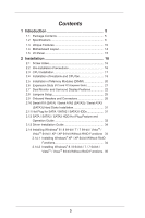
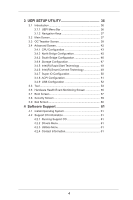
Motherboard Layout 14 1.5 I/O Panel 15 2 Installation 16 2.1 Screw Holes 16 2.2 Pre-installation Precautions 16 2.3 CPU Installation 17 2.4 Installation of Heatsink and CPU / SATA3 HDD Hot Plug Feature and Operation Guide 32 2.13 Driver Installation Guide 34 2.14 Installing Windows® 8 / 8 - ASRock B75M-DGS R2.0 | User Manual - Page 4
CPU Configuration 43 3.4.2 North Bridge Configuration 45 3.4.3 South Bridge Configuration 46 3.4.4 Storage Configuration 47 3.4.5 Intel(R) Rapid Start Technology 48 3.4.6 Intel Support 61 4.1 Install Operating System 61 4.2 Support CD Information 61 4.2.1 Running Support CD 61 4.2.2 Drivers - ASRock B75M-DGS R2.0 | User Manual - Page 5
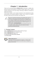
specific information about the model you are using. www.asrock.com/support/index.asp 1.1 Package Contents ASRock B75M-DGS R2.0 Motherboard (Micro ATX Form Factor) ASRock B75M-DGS R2.0 Quick Installation Guide ASRock B75M-DGS R2.0 Support CD 2 x Serial ATA (SATA) Data Cables (Optional) 1 x I/O Panel - ASRock B75M-DGS R2.0 | User Manual - Page 6
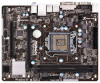
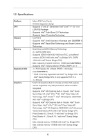
Platform CPU Chipset Memory Expansion Slot Graphics - Micro ATX Form Factor - All Solid Capacitor design - Supports 3rd and 2nd Generation Intel® CoreTM i7 / i5 / i3 in LGA1155 Package - Supports Intel® Turbo Boost 2.0 Technology - Supports Hyper-Threading Technology - Intel® B75 - Supports Intel - ASRock B75M-DGS R2.0 | User Manual - Page 7
1.1/2.0/3.0 up to 5Gb/s - 3 x SATA2 3.0 Gb/s connectors, support NCQ, AHCI and Hot Plug functions - 1 x SATA3 6.0Gb/s connector - 1 x IR header - 1 x Print port header - 1 x COM port header - 1 x Chassis Intrusion header - 1 x CPU Fan connector (4-pin) - 1 x Chassis Fan connector (4-pin) - 1 x Power - ASRock B75M-DGS R2.0 | User Manual - Page 8
Feature - 64Mb AMI UEFI Legal BIOS with GUI support - Supports "Plug and Play" - ACPI 1.1 Compliance Wake Up Events - Supports jumperfree - SMBIOS 2.3.1 Support - CPU Core, IGPU, DRAM, 1.8V PLL, VTT, VCCSA Voltage Multi-adjustment Support CD - Drivers, Utilities, AntiVirus Software (Trial - ASRock B75M-DGS R2.0 | User Manual - Page 9
please install an Ivy Bridge CPU. If you install a Sandy Bridge CPU, the PCI Express will run only at PCI Express Gen 2 speed. 4. ASRock XFast RAM is not supported by Microsoft® Windows® XP / XP 64-bit. Intel® Smart Connect Technology and Intel® USB 3.0 ports are not supported by Microsoft® Windows - ASRock B75M-DGS R2.0 | User Manual - Page 10
speed and temperature for you to adjust. In Overclocking, you are allowed to overclock CPU frequency for optimal system performance. In OC DNA, ASRock Instant Flash ASRock Instant Flash is a BIOS flash utility embedded in Flash ROM. This convenient BIOS update tool allows you to update system BIOS - ASRock B75M-DGS R2.0 | User Manual - Page 11
driver, it makes your iPhone charge much quickly from your computer and up to 40% faster than before. ASRock APP Charger allows you to quickly charge many Apple devices simultaneously and even supports Game: After setting online game's priority higher, it can lower the latency in games CPU. ASRock - ASRock B75M-DGS R2.0 | User Manual - Page 12
loss occurs during the BIOS update process, ASRock Crashless BIOS will automatically finish the BIOS update procedure after regaining power. Please note that BIOS files need to be placed in the root directory of your USB disk. Only USB2.0 ports support this feature. ASRock OMG (Online Management - ASRock B75M-DGS R2.0 | User Manual - Page 13
Night LED ASRock Good Night LED technology can offer you a better environment by extinguishing the unessential LED. By enabling Good Night LED in BIOS, the Power / HDD / LAN LED will be switched off when system is on. Not only this, Good night LED will automatically switch off Power and - ASRock B75M-DGS R2.0 | User Manual - Page 14
1 SPEAKER1 1 PLED PWRBTN 1 HDLED RESET PANEL1 Intel B75 SATA2_2 SATA2_3 1 CLRCMOS1 12 13 22 21 20 19 18 17 16 15 14 1 ATX 12V Power Connector (ATX12V1) 2 Power Fan Connector (PWR_FAN1) 3 ATX Power Connector (ATXPWR1) 4 1155-Pin CPU Socket 5 CPU Fan Connector (CPU_FAN1) 6 2 x 240-pin DDR3 - ASRock B75M-DGS R2.0 | User Manual - Page 15
1.5 I/O Panel 1 11 10 9 1 PS/2 Mouse Port (Green) * 2 LAN RJ-45 Port 3 Line In (Light Blue) ** 4 Front Speaker (Lime) 5 Microphone (Pink) 6 USB 2.0 Ports (USB23) 2 3 4 5 8 7 6 7 USB 3.0 Ports (USB3_01) 8 USB 2.0 Ports (USB01) 9 DVI-D Port (DVI1) 10 D-Sub Port (VGA1) 11 PS/2 Keyboard Port ( - ASRock B75M-DGS R2.0 | User Manual - Page 16
Chapter 2: Installation This is a Micro ATX form factor motherboard. Before you install the motherboard, study the configuration of your chassis to ensure that the motherboard fits into it. Make sure to unplug the power cord before installing or removing the motherboard. Failure to do so may cause - ASRock B75M-DGS R2.0 | User Manual - Page 17
of Intel 1155-Pin CPU, please follow the steps below. Load Plate Load Lever Contact Array Socket Body 1155-Pin Socket Overview Before you insert the 1155-Pin CPU into the socket, please check if the CPU the PnP cap. 2. This cap must be placed if returning the motherboard for after service. 17 - ASRock B75M-DGS R2.0 | User Manual - Page 18
key Pin1 Pin1 orientation key notch 1155-Pin CPU alignment key 1155-Pin Socket For proper inserting, please ensure to match the two orientation key notches of the CPU with the two alignment keys of the socket. Step 3-3. Carefully place the CPU into the socket by using a purely vertical motion - ASRock B75M-DGS R2.0 | User Manual - Page 19
Heatsink This motherboard is equipped with 1155-Pin socket that supports Intel 1155-Pin CPUs. Please adopt the type of heatsink and cooling fan compliant with Intel 1155Pin CPU to dissipate heat. Before you install the heatsink, you need to spray thermal interface material between the CPU and the - ASRock B75M-DGS R2.0 | User Manual - Page 20
2.5 Installation of Memory Modules (DIMM) This motherboard provides two 240-pin DDR3 (Double Data Rate 3) DIMM slots, and supports Dual Channel Memory Technology. For dual channel configuration, you always need to install two identical (the same brand, speed, size and chiptype) memory modules in - ASRock B75M-DGS R2.0 | User Manual - Page 21
Only PCIE1 slot supports Gen 3 speed. To run the PCI Express in Gen 3 speed, please install an Ivy Bridge CPU. If you install a Sandy Bridge CPU, the PCI the installation. Step 2. Remove the system unit cover (if your motherboard is already installed in a chassis). Step 3. Remove the bracket facing - ASRock B75M-DGS R2.0 | User Manual - Page 22
VGA card to this motherboard. This motherboard also provides independent display controllers for DVI-D and D-Sub to support dual VGA output so . D-Sub port DVI-D port 2. If you have installed onboard VGA driver from our support CD to your system already, you can freely enjoy the benefits of - ASRock B75M-DGS R2.0 | User Manual - Page 23
Display Feature This motherboard supports surround display upgrade. With the internal VGA output support (DVI-D and is inserted to this motherboard. 4. Install the onboard VGA driver and the add-on PCI Express VGA card driver to your system. If you have installed the drivers already, there is - ASRock B75M-DGS R2.0 | User Manual - Page 24
function is supported on this motherboard. To use HDCP function with this motherboard, you need to adopt the monitor that supports HDCP function as well. Therefore, you can enjoy the superior display quality with high-definition HDCP encryption contents. Please refer to below instruction for more - ASRock B75M-DGS R2.0 | User Manual - Page 25
need to clear the CMOS when you just finish updating the BIOS, you must boot up the system first, and then shut it down before you do the clear-CMOS action. Please be noted that the password, date, time, user default profile, 1394 GUID and MAC address will be cleared only if the - ASRock B75M-DGS R2.0 | User Manual - Page 26
No. 15) SATA2_2 SATA2_1 These three Serial ATA2 (SATA2) connectors support SATA data cables for internal storage devices. The current SATA2 interface SATA / SATA2 / SATA3 hard disk or the SATA2 / SATA3 connector on this motherboard. Print Port Header (25-pin LPT1) (see p.14, No. 21) AFD# - ASRock B75M-DGS R2.0 | User Manual - Page 27
panel, there is one USB 3.0 header on this motherboard. This USB 3.0 header can support two USB 3.0 ports. 1 Infrared Module Header (5-pin supports Jack Sensing, but the panel wire on the chassis must support HDA to function correctly. Please follow the instruction in our manual and chassis manual - ASRock B75M-DGS R2.0 | User Manual - Page 28
C. Connect Ground (GND) to Ground (GND). D. MIC_RET and OUT_RET are for HD audio panel only. You don't need to connect them for AC'97 audio panel. E. To activate the front mic. For Windows® XP / XP 64-bit OS: Select "Mixer". Select "Recorder". Then click "FrontMic". For Windows® 8 / 8 64-bit / 7 / 7 - ASRock B75M-DGS R2.0 | User Manual - Page 29
4-Pin CPU fan (Quiet Fan) support, the 3-Pin CPU fan still can work successfully even without the fan speed control function. If you plan to connect the 3-Pin CPU fan to the CPU fan connector on this motherboard, please connect it to Pin 1-3. Pin 1-3 Connected 3-Pin Fan Installation ATX Power - ASRock B75M-DGS R2.0 | User Manual - Page 30
Serial port Header (9-pin COM1) (see p.14, No. 20) This COM1 header supports a serial port module. Chassis Intrusion Header (2-pin CI1) (see p.14, No. 25) 1 GND Signal This motherboard supports CASE OPEN detection feature that detects if the chassis cover has been removed. - ASRock B75M-DGS R2.0 | User Manual - Page 31
) Hard Disks Installation This motherboard adopts Intel® B75 chipset that supports Serial ATA (SATA) / Serial ATA2 (SATA2) / Serial ATA3 (SATA3) hard disks. You may install SATA / SATA2 / SATA3 hard disks on this motherboard for internal storage devices. This section will guide you to install the - ASRock B75M-DGS R2.0 | User Manual - Page 32
installed into system properly. The latest SATA / SATA2 / SATA3 driver is available on our support website: www.asrock.com 4. Make sure to use the SATA power cable & data cable, which are from our motherboard package. 5. Please follow below instructions step by step to reduce the risk of HDD crash - ASRock B75M-DGS R2.0 | User Manual - Page 33
supply's 1x4-pin cable. Step 2 Connect SATA data cable to the motherboard's SATA2 / SATA3 connector. SATA power cable 1x4-pin power connector ( attention, before you process the Hot Unplug: Please do follow below instruction sequence to process the Hot Unplug, improper procedure will cause the SATA - ASRock B75M-DGS R2.0 | User Manual - Page 34
2.13 Driver Installation Guide To install the drivers to your system, please insert the support CD to your optical drive first. Then, the drivers compatible to your system can be auto-detected and listed on the support CD driver page. Please follow the order from top to bottom to install those - ASRock B75M-DGS R2.0 | User Manual - Page 35
2.14.2 Installing Windows® 8 / 8 64-bit / 7 / 7 64-bit / VistaTM / VistaTM 64-bit Without RAID Functions If you want to install Windows® 8 / 8 64-bit / 7 / 7 64-bit / VistaTM / VistaTM 64-bit OS on your SATA / SATA2 / SATA3 HDDs without RAID functions, please follow the steps below. Using SATA / - ASRock B75M-DGS R2.0 | User Manual - Page 36
to configure your system. The UEFI chip on the motherboard stores the UEFI SETUP UTILITY. You may run the Because the UEFI software is constantly being updated, the following UEFI setup screens and descriptions /date information OC Tweaker To set up overclocking features Advanced To set up the advanced - ASRock B75M-DGS R2.0 | User Manual - Page 37
3.1.2 Navigation Keys Please check the following table for the function description of each navigation key. Navigation Key(s) Function Description / Moves cursor left or right to select Screens / Moves cursor up or down to select items + / - To change option for the selected items - ASRock B75M-DGS R2.0 | User Manual - Page 38
overclocking features. CPU Configuration CPU Ratio Use this item to change the ratio value of this motherboard. Intel SpeedStep Technology Intel SpeedStep technology is Intel the current CPU does not support Intel SpeedStep technology. Please note that enabling this function may reduce CPU voltage - ASRock B75M-DGS R2.0 | User Manual - Page 39
GT OverClocking Support. The default value is [Disabled]. DRAM Timing Configuration Load XMP Setting Use this to load XMP setting. Configuration options: [Auto], [Default], [Profile 1] and [Profile 2]. The default value is [Auto]. DRAM Frequency If [Auto] is selected, the motherboard will detect - ASRock B75M-DGS R2.0 | User Manual - Page 40
setting. The default is [Auto]. DRAM tRTP Use this item to change Read to Precharge (tRTP) Auto/Manual setting. The default is [Auto]. DRAM tFAW Use this item to change Four Activate Window (tFAW) Auto/Manual setting. The default is [Auto]. DRAM tCWL Use this item to change CAS# Write Latency (tCWL - ASRock B75M-DGS R2.0 | User Manual - Page 41
tRRDR The default is [Auto]. tRRSR The default is [Auto]. tWWDD The default is [Auto]. tWWDR The default is [Auto]. tWWSR The default is [Auto]. RTL (CHA) Use this item to change RTL (CHA) setting. The default is [Auto]. RTL (CHB) Use this item to change RTL (CHB) setting. The default is [Auto]. IO - ASRock B75M-DGS R2.0 | User Manual - Page 42
this section, you may set the configurations for the following items: CPU Configuration, North Bridge Configuration, South Bridge Configuration, Storage Configuration, Intel(R) Rapid Start Technology, Intel(R) Smart Connect Technology, Super IO Configuration, ACPI Configuration and USB Configuration - ASRock B75M-DGS R2.0 | User Manual - Page 43
(C1). The C1 state is supported through the native processor instructions HLT and MWAIT and requires no hardware support from the chipset. In the C1 power state, the processor maintains the context of the system caches. CPU C3 State Support Use this to enable or disable CPU C3 (ACPI C2) report to - ASRock B75M-DGS R2.0 | User Manual - Page 44
pages from being used by malicious software to execute codes. This option will be hidden if the current CPU does not support No-Excute Memory Protection. Intel Virtualization Technology When this option is set to [Enabled], a VMM (Virtual Machine Architecture) can utilize the additional hardware - ASRock B75M-DGS R2.0 | User Manual - Page 45
[PCI] or [PCI Express] as the boot graphic adapter priority. The default value is [PCI Express]. VT-d Use this item to enable/disable Intel(R) Virtualization Technology for Directed I/O. PCIE1 Link Speed This allows you to select PCIE1 Link Speed. The default value is [Auto]. Share Memory - ASRock B75M-DGS R2.0 | User Manual - Page 46
HDMI HD Audio feature. Onboard LAN This allows you to enable or disable the Onboard LAN feature. Deep Sleep Mobile platforms support Deep S4/S5 in DC only and desktop platforms support Deep S4/S5 in AC only. The default value is [Enabled in S5]. Restore on AC/Power Loss This allows - ASRock B75M-DGS R2.0 | User Manual - Page 47
select SATA mode. Configuration options: [IDE Mode], [AHCI Mode] and [Disabled]. The default value is [AHCI Mode]. AHCI (Advanced Host Controller Interface) supports NCQ and other new features that will improve SATA disk performance but IDE mode does not have these advantages. SATA Aggressive Link - ASRock B75M-DGS R2.0 | User Manual - Page 48
Start Technology. Intel(R) Rapid Start Technology is a new zero power hibernation mode which allows users to resume in just 5-6 seconds. The default is [Enabled]. Entry After Select a time to enable RTC wake timer at S3 entry. The default is [10 minutes]. Active Page Threshold Support This allows - ASRock B75M-DGS R2.0 | User Manual - Page 49
(R) Smart Connect Technology Intel(R) Smart Connect Technology Use this item to enable or disable Intel(R) Smart Connect Technology. Intel(R) Smart Connect Technology keeps your e-mail and social networks, such as Twitter, Facebook, etc. updated automatically while the computer is in sleep mode. The - ASRock B75M-DGS R2.0 | User Manual - Page 50
3.4.7 Super IO Configuration Serial Port Use this item to enable or disable the onboard serial port. Serial Port Address Use this item to set the address for the onboard serial port. Configuration options: [3F8h / IRQ4] and [3E8h / IRQ4]. Infrared Port Use this item to enable or disable the onboard - ASRock B75M-DGS R2.0 | User Manual - Page 51
-toRAM feature. Selecting [Auto] will enable this feature if the OS supports it. Check Ready Bit Use this item to enable or disable the feature ]. Please set this option to [Enabled] if you plan to use this motherboard to submit Windows® certification. PS/2 Keyboard Power On Use this item to enable - ASRock B75M-DGS R2.0 | User Manual - Page 52
use of USB 2.0 controller. USB 3.0 Controller Use this item to enable or disable the use of USB 3.0 controller. Legacy USB Support Use this option to select legacy support for USB devices. There are four configuration options: [Enabled], [Auto], [Disabled] and [UEFI Setup Only]. The default value is - ASRock B75M-DGS R2.0 | User Manual - Page 53
or Windows®. Just save the new UEFI file to your USB flash drive, floppy disk or hard drive and launch this tool, then you can update your UEFI only in a few clicks without preparing an additional floppy diskette or other complicated flash utility. Please be noted that the USB flash drive - ASRock B75M-DGS R2.0 | User Manual - Page 54
searches for available UEFI firmware updates from our servers. In USA] and [China]. Dehumidifier Function Users may prevent motherboard damages due to dampness by enabling "Dehumidifier Function". Dehumidifier CPU Fan Setting Use this setting to configure CPU fan speed while "Dehumidifier" is enabled. - ASRock B75M-DGS R2.0 | User Manual - Page 55
Would you like to save current setting user defaults? In this option, you are allowed to load and save three user defaults according to your own requirements. 55 - ASRock B75M-DGS R2.0 | User Manual - Page 56
status of the hardware on your system, including the parameters of the CPU temperature, motherboard temperature, CPU fan speed, chassis fan speed, and the critical voltage. CPU Fan 1 Setting This allows you to set CPU fan 1's speed. Configuration options: [Full On] and [Automatic Mode]. The default - ASRock B75M-DGS R2.0 | User Manual - Page 57
not boot by using an USB flash drive. [Ultra Fast] - There are a few restrictions. 1. Only supports Windows® 8 UEFI operating system. 2. You will not be able to enter BIOS Setup (Clear CMOS or run utility in Widows® to enter BIOS Setup). 3. If you are using an external graphics card, the VBIOS must - ASRock B75M-DGS R2.0 | User Manual - Page 58
Full Screen Logo Use this item to enable or disable OEM Logo. The default value is [Enabled]. AddOn ROM Display Use this option to adjust AddOn ROM Display. If you enable the option "Full Screen Logo" but you want to see the AddOn ROM information when the system boots, please select [Enabled]. - ASRock B75M-DGS R2.0 | User Manual - Page 59
3.8 Security Screen In this section, you may set or change the supervisor/user password for the system. For the user password, you may also clear it. Secure Boot Use this to enable or disable Secure Boot. The default value is [Disabled]. 59 - ASRock B75M-DGS R2.0 | User Manual - Page 60
3.9 Exit Screen Save Changes and Exit When you select this option, it will pop-out the following message, "Save configuration changes and exit setup?" Select [OK] to save the changes and exit the UEFI SETUP UTILITY. Discard Changes and Exit When you select this option, it will pop-out the following - ASRock B75M-DGS R2.0 | User Manual - Page 61
install the necessary drivers to activate the devices. 4.2.3 Utilities Menu The Utilities Menu shows the application softwares that the motherboard supports. Click on a specific item then follow the installation wizard to install it. 4.2.4 Contact Information If you need to contact ASRock or want to - ASRock B75M-DGS R2.0 | User Manual - Page 62
Installing OS on a HDD Larger Than 2TB in AHCI Mode This motherboard adopts UEFI BIOS that allows Windows® OS to be installed on a large size HDD (>2TB). Please follow the procedures below to install the operating system. 1. Please make sure
-
 1
1 -
 2
2 -
 3
3 -
 4
4 -
 5
5 -
 6
6 -
 7
7 -
8
-
9
-
10
-
11
-
12
-
13
-
14
-
15
-
16
-
17
-
18
-
19
-
20
-
21
-
22
-
23
-
24
-
25
-
26
-
27
-
28
-
29
-
30
-
31
-
32
-
33
-
34
-
35
-
36
-
37
-
38
-
39
-
40
-
41
-
42
-
43
-
44
-
45
-
46
-
47
-
48
-
49
-
50
-
51
-
52
-
53
-
54
-
55
-
56
-
57
-
58
-
59
-
60
-
61
-
62
 |
 |

1
B75M-DGS R2.0
User Manual
Version 1.0
Published December 2012
Copyright©2012 ASRock INC. All rights reserved.