ASRock B75M-GL User Manual
ASRock B75M-GL Manual
 |
View all ASRock B75M-GL manuals
Add to My Manuals
Save this manual to your list of manuals |
ASRock B75M-GL manual content summary:
- ASRock B75M-GL | User Manual - Page 1
B75M-GL User Manual Version 1.0 Published May 2012 Copyright©2012 ASRock INC. All rights reserved. 1 - ASRock B75M-GL | User Manual - Page 2
purchaser for backup purpose, without written consent of ASRock Inc. Products and corporate names appearing in this manual may or may not be registered trademarks or copyrights USA ONLY The Lithium battery adopted on this motherboard contains Perchlorate, a toxic substance controlled in Perchlorate - ASRock B75M-GL | User Manual - Page 3
Plug Feature and Operation Guide 37 2.17 Driver Installation Guide 39 2.18 Installing Windows® 7 / 7 64-bit / VistaTM / VistaTM 64-bit / XP / XP 64-bit Without RAID Functions 39 2.18.1 Installing Windows® XP / XP 64-bit Without RAID Functions 39 2.18.2 Installing Windows® 7 / 7 64-bit / VistaTM - ASRock B75M-GL | User Manual - Page 4
CPU Configuration 48 3.4.2 North Bridge Configuration 50 3.4.3 South Bridge Configuration 51 3.4.4 Storage Configuration 52 3.4.5 Intel(R) Rapid Start Technology 53 3.4.6 Intel Support 62 4.1 Install Operating System 62 4.2 Support CD Information 62 4.2.1 Running Support CD 62 4.2.2 Drivers - ASRock B75M-GL | User Manual - Page 5
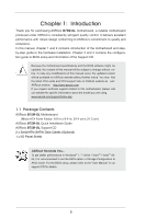
Contents ASRock B75M-GL Motherboard (Micro ATX Form Factor: 9.6-in x 8.4-in, 24.4 cm x 21.3 cm) ASRock B75M-GL Quick Installation Guide ASRock B75M-GL Support CD 2 x Serial ATA (SATA) Data Cables (Optional) 1 x I/O Panel Shield ASRock Reminds You... To get better performance in Windows® 7 / 7 64 - ASRock B75M-GL | User Manual - Page 6
Graphics - Micro ATX Form Factor: 9.6-in x 8.4-in, 24.4 cm x 21.3 cm - Solid Capacitors for CPU power - Supports 3rd and 2nd Generation Intel® CoreTM i7 / i5 / i3 in LGA1155 Package - Supports Intel® Turbo Boost 2.0 Technology - Supports Intel® K-Series unlocked CPU (see CAUTION 1) - Supports Hyper - ASRock B75M-GL | User Manual - Page 7
1 x CPU Fan connector (4-pin) - 1 x Chassis Fan connector (4-pin) - 1 x Power Fan connector (3-pin) - 24 pin ATX power connector - 4 pin 12V power connector - Front panel audio connector - 2 x USB 2.0 headers (support 4 USB 2.0 ports) - 64Mb AMI UEFI Legal BIOS with GUI support - Supports "Plug and - ASRock B75M-GL | User Manual - Page 8
Instant Flash (see CAUTION 9) - ASRock APP Charger (see CAUTION 10) - ASRock SmartView (see CAUTION 11) - ASRock XFast USB (see CAUTION 12) - ASRock XFast LAN (see CAUTION 13) - ASRock XFast RAM (see CAUTION 14) - ASRock Crashless BIOS (see CAUTION 15) - ASRock OMG (Online Management Guard - ASRock B75M-GL | User Manual - Page 9
may be less than 4GB for the reservation for system usage under Windows® 7 / VistaTM / XP. For Windows® OS with 64-bit CPU, there is no such limitation. You can use ASRock XFast RAM to utilize the memory that Windows® cannot use. 6. Only PCIE1 slot supports Gen 3 speed. To run the PCI Express in Gen - ASRock B75M-GL | User Manual - Page 10
BIOS update tool allows you to update system BIOS without entering operating systems first like MS-DOS or Windows®. With this utility, you can press the key during the POST or the key to enter into the BIOS setup menu to access ASRock Instant Flash. Just launch this tool and save the new - ASRock B75M-GL | User Manual - Page 11
CPU cooler types, Socket LGA 775, LGA 1155 and LGA 1156. Please be noticed that not all the 775 and 1156 CPU Fan can be used. 21. ASRock XFast RAM is not supported by Microsoft® Windows® XP / XP 64-bit. Intel® Smart Connect Technology and Intel® USB 3.0 ports are not supported by Microsoft® Windows - ASRock B75M-GL | User Manual - Page 12
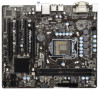
PWR_FAN1) 2 ATX 12V Power Connector (ATX12V1) 3 1155-Pin CPU Socket 4 CPU Fan Connector (CPU_FAN1) 5 2 x 240-pin DDR3 DIMM Slots (DDR3_A1, DDR3_B1, Black) 6 ATX Power Connector (ATXPWR1) 7 SATA3 Connector (SATA3_0, Gray) 8 Chassis Fan Connector (CHA_FAN1) 9 Intel B75 Chipset 10 SPI Flash - ASRock B75M-GL | User Manual - Page 13
10 DVI-D Port (DVI1) 11 PS/2 Keyboard Port (Purple) * There is one LED next to the LAN port. Please refer to the table below for the LAN port LED indications. LAN to below steps for the software setting of Multi-Streaming. For Windows® XP: After restarting your computer, you will find "Mixer" - ASRock B75M-GL | User Manual - Page 14
This is a Micro ATX form factor (9.6" x 8.4", 24.4 x 21.3 cm) motherboard. Before you install the motherboard, study the configuration of your chassis to ensure that the motherboard fits into it. Make sure to unplug the power cord before installing or removing the motherboard. Failure to do - ASRock B75M-GL | User Manual - Page 15
Intel 1155-Pin CPU, please follow the steps below. 1155-Pin Socket Overview Before you insert the 1155-Pin CPU into the socket, please check if the CPU surface is unclean or if there are any bent pins in the socket. Do not force to insert the CPU into the socket the motherboard for after service. 15 - ASRock B75M-GL | User Manual - Page 16
key Pin1 Pin1 orientation key notch 1155-Pin CPU alignment key 1155-Pin Socket For proper inserting, please ensure to match the two orientation key notches of the CPU with the two alignment keys of the socket. Step 3-3. Carefully place the CPU into the socket by using a purely vertical motion - ASRock B75M-GL | User Manual - Page 17
operation or contact other components. Please be noticed that this motherboard supports Combo Cooler Option (C.C.O.), which provides flexible options to adopt three different CPU cooler types, Socket LGA 775, LGA 1155 and LGA 1156. The white throughholes are for Socket LGA 1155/1156 CPU fan. 17 - ASRock B75M-GL | User Manual - Page 18
2.5 Installation of Memory Modules (DIMM) This motherboard provides two 240-pin DDR3 (Double Data Rate 3) DIMM slots, and supports Dual Channel Memory Technology. For dual channel configuration, you always need to install two identical (the same brand, speed, size and chiptype) memory modules in - ASRock B75M-GL | User Manual - Page 19
to the motherboard's chassis fan connector (CHA_FAN1) when using multiple graphics cards for better thermal environment. 4. Only PCIE1 slot supports Gen 3 speed . To run the PCI Express in Gen 3 speed, please install an Ivy Bridge CPU. If you install a Sandy Bridge CPU, the - ASRock B75M-GL | User Manual - Page 20
Guide This motherboard supports supported by Windows® XP with Service Pack 2 / VistaTM / 7 OS. Quad CrossFireXTM is supported by Windows® VistaTM / 7 OS only. Please check AMD's website for AMD CrossFireXTM driver updates to AMD graphics card manuals for detailed installation guide. Step 1. Insert - ASRock B75M-GL | User Manual - Page 21
Bridge Interconnects on the top of the Radeon graphics cards. (The CrossFire Bridge is provided with the graphics card you purchase, not bundled with this motherboard. Please refer to your graphics card vendor for details.) CrossFire Bridge or Step 3. Connect the DVI monitor cable to the DVI - ASRock B75M-GL | User Manual - Page 22
. Please check AMD's website for AMD driver updates. Step 3. Step 4. Step 5. Install the required drivers to your system. For Windows® XP OS: A. AMD recommends Windows® XP Service Pack 2 or higher to be installed (If you have Windows® XP Service Pack 2 or higher installed in your system - ASRock B75M-GL | User Manual - Page 23
for identification or explanation and to the owners' benefit, without intent to infringe. * For further information of AMD CrossFireXTM technology, please check AMD's website for updates and details. 23 - ASRock B75M-GL | User Manual - Page 24
VGA cards to this motherboard. This motherboard also provides independent display controllers for DVI-D and D-Sub to support dual VGA output so port DVI-D port 2. If you have already installed the onboard VGA driver from our support CD to your system, you can freely enjoy the benefits of dual - ASRock B75M-GL | User Manual - Page 25
motherboard. 4. Install the onboard VGA driver and the add-on PCI Express VGA card driver to your system. If you have installed the drivers already, there is no need to install them again. 5. Set up a multi-monitor display. For Windows " to apply these new values. G. Repeat steps C through F for the - ASRock B75M-GL | User Manual - Page 26
HDCP is supported on this motherboard. To use HDCP on this motherboard, you need to adopt a monitor that supports HDCP as well. Therefore, you can enjoy the superior display quality with high-definition HDCP encryption contents. Please refer to the instructions below for - ASRock B75M-GL | User Manual - Page 27
this option, please shut down your system and install the Multi-Angle CIR Receiver to the other front USB port then try again. Step5. Enter Windows. Execute ASRock's support CD and install the CIR Driver. (It is listed at the bottom of driver list.) 27 - ASRock B75M-GL | User Manual - Page 28
most of the chassis on the market. 3. The Multi-Angle CIR Receiver does not support Hot-Plug. Please install it before you boot the system. * ASRock Smart Remote is only supported by some ASRock motherboards. Please refer to ASRock's website for the motherboard support list: http://www.asrock.com 28 - ASRock B75M-GL | User Manual - Page 29
2.10 Jumpers Setup The illustration shows how jumpers are setup. When the jumper cap just finish updating the BIOS, you must boot up the system first, and then shut it down before you do the clear-CMOS action. Please be noted that the password, date, time, user default profile, 1394 GUID and MAC - ASRock B75M-GL | User Manual - Page 30
Placing jumper caps over the headers and connectors will cause permanent damage of the motherboard! Serial ATA2 Connectors (SATA2_1: see p.12, No. 11) (SATA2_2: SATA2_2 SATA2_4 SATA2_5 These five Serial ATA2 (SATA2) connectors support SATA data cables for internal storage devices. The current SATA2 - ASRock B75M-GL | User Manual - Page 31
2.0 headers on this motherboard. Each USB 2.0 header can support two USB 2.0 ports. This header supports an optional wireless transmitting supports Jack Sensing, but the panel wire on the chassis must support HDA to function correctly. Please follow the instructions in our manual and chassis manual - ASRock B75M-GL | User Manual - Page 32
® XP / XP 64-bit OS: Select "Mixer". Select "Recorder". Then click "FrontMic". For Windows® 7 / 7 64-bit / VistaTM / VistaTM 64-bit OS: Go to the "FrontMic" Tab in the Realtek Control panel. Adjust "Recording Volume". System Panel Header (9-pin PANEL1) ( - ASRock B75M-GL | User Manual - Page 33
4-Pin CPU fan (Quiet Fan) support, the 3-Pin CPU fan still can work successfully even without the fan speed control function. If you plan to connect the 3-Pin CPU fan to the CPU fan connector on this motherboard, please connect it to Pin 1-3. Pin 1-3 Connected 3-Pin Fan Installation ATX Power - ASRock B75M-GL | User Manual - Page 34
Serial port Header (9-pin COM1) (see p.12, No. 22) This COM1 header supports a serial port module. 34 - ASRock B75M-GL | User Manual - Page 35
ATA2 (SATA2) Hard Disks Installation This motherboard adopts Intel® B75 chipset that supports Serial ATA (SATA) / Serial ATA2 (SATA2) hard disks. You may install SATA / SATA2 hard disks on this motherboard for internal storage devices. This section will guide you to install the SATA / SATA2 hard - ASRock B75M-GL | User Manual - Page 36
SATA / SATA2 HDD. 2.15 Hot Plug for SATA3 HDDs This motherboard supports Hot Plug for SATA3 in AHCI mode. The Intel® B75 chipset provides hardware support for Advanced Host controller Interface (AHCI), a new programming interface for SATA host controllers developed through a joint industry effort - ASRock B75M-GL | User Manual - Page 37
installed into system properly. The latest SATA / SATA2 / SATA3 driver is available on our support website: www.asrock.com 4. Make sure to use the SATA power cable & data cable, which are from our motherboard package. 5. Please follow below instructions step by step to reduce the risk of HDD crash - ASRock B75M-GL | User Manual - Page 38
supply's 1x4-pin cable. Step 2 Connect SATA data cable to the motherboard's SATA2 / SATA3 connector. SATA power cable 1x4-pin power connector ( attention, before you process the Hot Unplug: Please do follow below instruction sequence to process the Hot Unplug, improper procedure will cause the SATA - ASRock B75M-GL | User Manual - Page 39
auto-detected and listed on the support CD driver page. Please follow the order from top to bottom to install those required drivers. Therefore, the drivers you install can work properly. 2.18 Installing Windows® 7 / 7 64-bit / VistaTM / VistaTM 64-bit / XP / XP 64-bit Without RAID Functions If you - ASRock B75M-GL | User Manual - Page 40
® 7 / 7 64-bit / VistaTM / VistaTM 64-bit Without RAID Functions If you want to install Windows® 7 / 7 64-bit / VistaTM / VistaTM 64-bit OS on your SATA / SATA2 / SATA3 HDDs without RAID functions, please follow the steps below. Using SATA / SATA2 / SATA3 HDDs with NCQ function STEP 1: Set Up - ASRock B75M-GL | User Manual - Page 41
configure your system. The UEFI chip on the motherboard stores the UEFI SETUP UTILITY. You may run the Because the UEFI software is constantly being updated, the following UEFI setup screens and descriptions /date information OC Tweaker To set up overclocking features Advanced To set up the advanced UEFI - ASRock B75M-GL | User Manual - Page 42
3.1.2 Navigation Keys Please check the following table for the descriptions of each navigation key. Navigation Key(s) Function Description + / - To change option for the selected items Switch to next function Go to the previous page Go to the next page Go to - ASRock B75M-GL | User Manual - Page 43
In the OC Tweaker screen, you can set up overclocking features. CPU Configuration CPU Ratio Use this item to change the ratio value of this motherboard. Intel SpeedStep Technology Intel SpeedStep technology is Intel's new power saving technology. Processors can switch between multiple frequencies - ASRock B75M-GL | User Manual - Page 44
GT OverClocking Support. The default value is [Disabled]. DRAM Timing Configuration Load XMP Setting Use this to load XMP setting. Configuration options: [Auto], [Default], [Profile 1] and [Profile 2]. The default value is [Auto]. DRAM Frequency If [Auto] is selected, the motherboard will detect - ASRock B75M-GL | User Manual - Page 45
setting. The default is [Auto]. DRAM tRTP Use this item to change Read to Precharge (tRTP) Auto/Manual setting. The default is [Auto]. DRAM tFAW Use this item to change Four Activate Window (tFAW) Auto/Manual setting. The default is [Auto]. DRAM tCWL Use this item to change CAS# Write Latency (tCWL - ASRock B75M-GL | User Manual - Page 46
Voltage Offset Use this to select CPU Core Voltage. The default value is [Auto]. IGPU Auto]. PCH Voltage Use this to select PCH Voltage. The default value is [Auto]. CPU PLL Voltage Use this to select CPU PLL Voltage. The default value is [Auto]. VCCSA Voltage Use this to select VCCSA Voltage - ASRock B75M-GL | User Manual - Page 47
CPU Configuration, North Bridge Configuration, South Bridge Configuration, Storage Configuration, Intel(R) Rapid Start Technology, Intel This convenient UEFI update tool allows you to update system UEFI without entering operating systems first like MS-DOS or Windows®. Just save the new UEFI file to - ASRock B75M-GL | User Manual - Page 48
3.4.1 CPU Configuration Intel Hyper Threading Technology To enable this feature, a computer system with an Intel processor that supports Hyper-Threading technology and an operating system that includes optimization for this technology, such as Microsoft® Windows® XP / VistaTM / 7 is required. Set to - ASRock B75M-GL | User Manual - Page 49
Memory Protection" can prevent data pages from being used by malicious software to execute codes. This option will be hidden if the current CPU does not support No-Excute Memory Protection. Intel Virtualization Technology When this option is set to [Enabled], a VMM (Virtual Machine Architecture) can - ASRock B75M-GL | User Manual - Page 50
value is [PCI Express]. VT-d Use this item to enable/disable Intel(R) Virtualization Technology for Directed I/O. PCIE1 Link Speed This allows you to [Disabled]. If you wish to install a PCI Express card under Windows® XP / VistaTM OS, please disable this option. Render Standby Use - ASRock B75M-GL | User Manual - Page 51
This allows you to enable or disable the Onboard HDMI HD Audio feature. Onboard LAN This allows you to enable or disable the Onboard LAN feature. Deep Sleep Mobile platforms support Deep S4/S5 in DC only and desktop platforms support Deep S4/S5 in AC only. The default value is [Enabled in S5 - ASRock B75M-GL | User Manual - Page 52
SATA mode. Configuration options: [IDE Mode] and [AHCI Mode]. The default value is [AHCI Mode]. AHCI (Advanced Host Controller Interface) supports NCQ and other new features that will improve SATA disk performance but IDE mode does not have these advantages. SATA Aggressive Link Power Management Use - ASRock B75M-GL | User Manual - Page 53
Start Technology. Intel(R) Rapid Start Technology is a new zero power hibernation mode which allows users to resume in just 5-6 seconds. The default is [Enabled]. Entry After Select a time to enable RTC wake timer at S3 entry. The default is [10 minutes]. Active Page Threshold Support This allows - ASRock B75M-GL | User Manual - Page 54
(R) Smart Connect Technology Intel(R) Smart Connect Technology Use this item to enable or disable Intel(R) Smart Connect Technology. Intel(R) Smart Connect Technology keeps your e-mail and social networks, such as Twitter, Facebook, etc. updated automatically while the computer is in sleep mode. The - ASRock B75M-GL | User Manual - Page 55
3.4.7 Super IO Configuration Serial Port Use this item to enable or disable the onboard serial port. Serial Port Address Use this item to set the address for the onboard serial port. Configuration options: [3F8h / IRQ4] and [3E8h / IRQ4]. Infrared Port Use this item to enable or disable the onboard - ASRock B75M-GL | User Manual - Page 56
OS supports it. Check Ready Bit Use this item to enable or disable the feature Check Ready Bit. ACPI HPET Table Use this item to enable or disable ACPI HPET Table. The default value is [Enabled]. Please set this option to [Enabled] if you plan to use this motherboard to submit Windows® VistaTM - ASRock B75M-GL | User Manual - Page 57
issues, it is recommended to select [Disabled] to enter OS. [UEFI Setup Only] - USB devices are allowed to use only under UEFI setup and Windows / Linux OS. Legacy USB 3.0 Support Use this option to enable or disable legacy support for USB 3.0 devices. The default value is [Enabled]. 57 - ASRock B75M-GL | User Manual - Page 58
status of the hardware on your system, including the parameters of the CPU temperature, motherboard temperature, CPU fan speed, chassis fan speed, and the critical voltage. CPU Fan 1 Setting This allows you to set CPU fan 1's speed. Configuration options: [Full On] and [Automatic Mode]. The default - ASRock B75M-GL | User Manual - Page 59
Enable or disable the feature of Boot Failure Guard. Boot Failure Guard Count Use this item to configure Boot Failure Guard Count. Boot From Onboard LAN Use this item to enable or disable the Boot From Onboard - ASRock B75M-GL | User Manual - Page 60
3.7 Security Screen In this section, you may set or change the supervisor/user password for the system. For the user password, you may also clear it. 60 - ASRock B75M-GL | User Manual - Page 61
3.8 Exit Screen Save Changes and Exit When you select this option, the following message "Save configuration changes and exit setup?" will pop-out. Select [Yes] to save the changes and exit the UEFI SETUP UTILITY. Discard Changes and Exit When you select this option, the following message "Discard - ASRock B75M-GL | User Manual - Page 62
install the necessary drivers to activate the devices. 4.2.3 Utilities Menu The Utilities Menu shows the application softwares that the motherboard supports. Click on a specific item then follow the installation wizard to install it. 4.2.4 Contact Information If you need to contact ASRock or want to - ASRock B75M-GL | User Manual - Page 63
Installing OS on a HDD Larger Than 2TB in AHCI Mode This motherboard adopts UEFI BIOS that allows Windows® OS to be installed on a large size HDD (>2TB). Please follow the procedures below to install the operating system. 1. Please make sure to use Windows® VistaTM 64-bit (with SP2 or above) or
-
 1
1 -
 2
2 -
 3
3 -
 4
4 -
 5
5 -
 6
6 -
 7
7 -
8
-
9
-
10
-
11
-
12
-
13
-
14
-
15
-
16
-
17
-
18
-
19
-
20
-
21
-
22
-
23
-
24
-
25
-
26
-
27
-
28
-
29
-
30
-
31
-
32
-
33
-
34
-
35
-
36
-
37
-
38
-
39
-
40
-
41
-
42
-
43
-
44
-
45
-
46
-
47
-
48
-
49
-
50
-
51
-
52
-
53
-
54
-
55
-
56
-
57
-
58
-
59
-
60
-
61
-
62
-
63
 |
 |

1
B75M-GL
User Manual
Version 1.0
Published May 2012
Copyright©2012 ASRock INC. All rights reserved.