ASRock B75M-ITX User Manual
ASRock B75M-ITX Manual
 |
View all ASRock B75M-ITX manuals
Add to My Manuals
Save this manual to your list of manuals |
ASRock B75M-ITX manual content summary:
- ASRock B75M-ITX | User Manual - Page 1
B75M-ITX User Manual Version 1.0 Published March 2012 Copyright©2012 ASRock INC. All rights reserved. 1 - ASRock B75M-ITX | User Manual - Page 2
purchaser for backup purpose, without written consent of ASRock Inc. Products and corporate names appearing in this manual may or may not be registered trademarks or copyrights , USA ONLY The Lithium battery adopted on this motherboard contains Perchlorate, a toxic substance controlled in Perchlorate - ASRock B75M-ITX | User Manual - Page 3
installation Precautions 16 2.3 CPU Installation 17 2.4 Installation of Heatsink and CPU fan 19 2.5 Installation of Memory Modules (DIMM 20 2.6 Expansion Slot (PCI Express Slot 21 2.7 Dual Monitor and Surround Display Features 22 2.8 ASRock Smart Remote Installation Guide 25 2.9 Jumpers Setup - ASRock B75M-ITX | User Manual - Page 4
38 3.4 Advanced Screen 42 3.4.1 CPU Con guration 43 3.4.2 North Bridge Con guration 45 3.4.3 South Bridge Con guration 46 3.4.4 Storage Con 55 4 Software Support 56 4.1 Install Operating System 56 4.2 Support CD Information 56 4.2.1 Running Support CD 56 4.2.2 Drivers Menu 56 4.2.3 - ASRock B75M-ITX | User Manual - Page 5
guide to BIOS setup and information of the Support CD. Because the motherboard speci cations and the BIOS software might be updated, the content of this manual will be subject to change without notice. In case any modi cations of this manual occur, the updated version will be available on ASRock - ASRock B75M-ITX | User Manual - Page 6
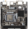
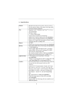
Platform CPU Chipset Memory Expansion Slot Graphics - Mini-ITX Form Factor: 6.7-in x 6.7-in, 17.0 cm x 17.0 cm - All Solid Capacitor design (100% Japan-made high-quality Conductive Polymer Capacitors) - Supports 3rd and 2nd Generation Intel® CoreTM i7 / i5 / i3 in LGA1155 Package - Digi Power - ASRock B75M-ITX | User Manual - Page 7
Port with LED (ACT/LINK LED and SPEED LED) - HD Audio Jack: Rear Speaker/Central/Bass/Line in/Front Speaker/Microphone (see CAUTION 10) - 1 x SATA3 6.0 Gb/s connector, supports NCQ, AHCI and Hot Plug functions - 2 x Rear USB 3.0 ports, support USB 1.0/2.0/3.0 up to 5Gb/s - 1 x Front USB 3.0 header - ASRock B75M-ITX | User Manual - Page 8
BIOS with GUI support - Supports "Plug and Play" - ACPI 1.1 Compliance Wake Up Events - Supports jumperfree - SMBIOS 2.3.1 Support - CPU Core, IGPU, DRAM, 1.8V PLL, VTT, VCCSA Voltage Multi-adjustment - Drivers, Utilities, AntiVirus Software (Trial Version), CyberLink MediaEspresso 6.5 Trial, ASRock - ASRock B75M-ITX | User Manual - Page 9
Center, Data Backup & Restore, Energy Saver and USB Blocker. 4. This motherboard supports Dual Channel Memory Technology. Before you implement Dual Channel Memory Technology, make sure to read the installation guide of memory modules on page 20 for proper installation. 5. Due to the operating system - ASRock B75M-ITX | User Manual - Page 10
the CPU cores are idle without sacri cing computing performance. Please visit our website for the operation procedures of ASRock Extreme Tuning Utility (AXTU). ASRock website: http://www.asrock.com 12. ASRock Instant Flash is a BIOS ash utility embedded in Flash ROM. This convenient BIOS update tool - ASRock B75M-ITX | User Manual - Page 11
update their BIOS without fear of failing. If power loss occurs during the BIOS update process, ASRock Crashless BIOS will automatically nish the BIOS update procedure after regaining power. Please note that BIOS les need to be placed in the root directory of your USB disk. Only USB2.0 ports support - ASRock B75M-ITX | User Manual - Page 12
check if the CPU fan on the motherboard functions properly and unplug the power cord, then plug it back again. To improve heat dissipation, remember to spray thermal grease between the CPU and the heatsink when you install the PC system. 23. ASRock XFast RAM is not supported by Microsoft® Windows - ASRock B75M-ITX | User Manual - Page 13
) 6 Intel B75 Chipset 7 USB 2.0 Header (USB4_5, Black) 8 System Panel Header (PANEL1, Black) 9 ATX Power Connector (ATXPWR1) 10 Consumer Infrared Module Header (CIR1, Gray) 14 13 11 2 x 240-pin DDR3 DIMM Slots (DDR3_A1, DDR3_B1, Black) 12 USB 3.0 Header (USB3_3_4, Black) 13 1155-Pin CPU Socket 14 - ASRock B75M-ITX | User Manual - Page 14
2 15 14 1 USB 2.0 Ports (USB01) 2 D-Sub Port (VGA1) 3 USB 2.0 Ports (USB23) * 4 LAN RJ-45 Port 5 Central / Bass (Orange) 6 Rear Speaker (Black) 7 Line In (Light Blue) ** 8 Front Speaker (Lime) 34 57 68 9 13 12 11 10 9 Microphone (Pink) 10 Optical SPDIF Out Port 11 USB 3.0 Ports (USB3_12) 12 - ASRock B75M-ITX | User Manual - Page 15
multi-streaming", and click "ok". Choose "2CH", "4CH", "6CH", or "8CH" and then you are allowed to select "Realtek HDA Primary output" to use Rear Speaker, Central/Bass, and Front Speaker, or select "Realtek HDA Audio 2nd output" to use front panel audio. 15 - ASRock B75M-ITX | User Manual - Page 16
Installation This is a Mini-ITX form factor (6.7" x 6.7", 17.0 x 17.0 cm) motherboard. Before you install the motherboard, study the con guration of your chassis to ensure that the motherboard ts into it. Make sure to unplug the power cord before installing or removing the motherboard. Failure to do - ASRock B75M-ITX | User Manual - Page 17
Intel 1155-Pin CPU, please follow the steps below. Load Plate Load Lever Contact Array Socket Body 1155-Pin Socket Overview Before you insert the 1155-Pin CPU into the socket, please check if the CPU surface PnP cap. 2. This cap must be placed if returning the motherboard for after service. 17 - ASRock B75M-ITX | User Manual - Page 18
key notches. orientation key notch alignment key Pin1 Pin1 orientation key notch 1155-Pin CPU alignment key 1155-Pin Socket For proper inserting, please ensure to match the two orientation key notches of the CPU with the two alignment keys of the socket. Step 3-3. Carefully place the - ASRock B75M-ITX | User Manual - Page 19
(CPU_ FAN1, see page 13, No. 16). For proper installation, please kindly refer to the instruction manuals of your CPU fan and heatsink. Below is an example to illustrate the installation of the heatsink for 1155-Pin CPUs. Step 1. Apply thermal interface material onto the cen- ter of the IHS on the - ASRock B75M-ITX | User Manual - Page 20
2.5 Installation of Memory Modules (DIMM) This motherboard provides two 240-pin DDR3 (Double Data Rate 3) DIMM slots, and supports Dual Channel Memory Technology. For dual channel configuration, you always need to install two identical (the same brand, speed, size and chiptype) memory modules in the - ASRock B75M-ITX | User Manual - Page 21
install an Ivy Bridge CPU. If you install a Sandy Bridge CPU, the PCI Express will run only at PCI Express Gen 2 speed. Installing an expansion card Step 1. Step 2. Step 3. Step 4. Step 5. Step 6. Before installing an expansion card, please make sure that the power supply is switched off or - ASRock B75M-ITX | User Manual - Page 22
motherboard supports dual monitor feature. With the internal VGA output support (DVI-D, D-Sub and HDMI), you can easily enjoy the bene ts of dual monitor feature without installing any add-on VGA cards to this motherboard. This motherboard installed the onboard VGA driver from our support CD to your - ASRock B75M-ITX | User Manual - Page 23
This motherboard supports surround display upgrade. With the internal VGA output support ( memory. If you do not adjust the UEFI setup, the default value of "Share Memory", [Auto], will disable D-Sub function when an add-on VGA card is inserted to this motherboard. 4. Install the onboard VGA driver - ASRock B75M-ITX | User Manual - Page 24
. To use HDCP function with this motherboard, you need to adopt a monitor that supports HDCP function as well. Therefore, you can enjoy the superior display quality with high-de nition HDCP encryption contents. Please refer to the instructions below for more details about HDCP function. What - ASRock B75M-ITX | User Manual - Page 25
on the market. 3. The Multi-Angle CIR Receiver does not support Hot-Plug function. Please install it before you boot the system. * ASRock Smart Remote is only supported by some of ASRock's motherboards. Please refer to ASRock's website for the motherboard support list: http://www.asrock.com 25 - ASRock B75M-ITX | User Manual - Page 26
setup, please turn off the computer and unplug the power cord from the power supply. After waiting for 15 seconds, use a jumper cap to short pin2 and pin3 on CLRCMOS1 for 5 seconds. However, please do not clear the CMOS right after you update the BIOS. If you need to clear the CMOS when you - ASRock B75M-ITX | User Manual - Page 27
jumper caps over the headers and connectors will cause permanent damage of the motherboard! Serial ATA2 Connectors (SATA_1: see p.13, No. 2) (SATA_2: p.13, No. 3) SATA_0 This Serial ATA3 (SATA3) connector supports SATA data cables for internal storage devices. The current SATA3 interface allows - ASRock B75M-ITX | User Manual - Page 28
one USB 3.0 header on this motherboard. This USB 3.0 header can support two USB 3.0 ports. Consumer Infrared Module Header (4-pin CIR1) (see supports Jack Sensing, but the panel wire on the chassis must support HDA to function correctly. Please follow the instruction in our manual and chassis manual - ASRock B75M-ITX | User Manual - Page 29
module mainly consists of power switch, reset switch, power LED, hard drive activity LED, speaker and etc. When connecting your chassis front panel module pin. CPU Fan Connectors (4-pin CPU_FAN1) (see p.13, No. 16) FAN_SPEED_CONTROL 4 CPU_FAN_SPEED 3 +12V 2 GND 1 Please connect the CPU fan - ASRock B75M-ITX | User Manual - Page 30
(Quiet Fan) support, the 3-Pin CPU fan still can work successfully even without the fan speed control function. If you plan to connect the 3-Pin CPU fan to the CPU fan connector on this motherboard, please connect it to Pin 1-3. Pin 1-3 Connected 3-Pin Fan Installation ATX Power Connector 24 - ASRock B75M-ITX | User Manual - Page 31
) Hard Disks Installation This motherboard adopts Intel® B75 chipset that supports Serial ATA (SATA) / Serial ATA2 (SATA2) / Serial ATA3 (SATA3) hard disks. You may install SATA / SATA2 / SATA3 hard disks on this motherboard for internal storage devices. This section will guide you to install the - ASRock B75M-ITX | User Manual - Page 32
installed into system properly. The latest SATA / SATA2 / SATA3 driver is available on our support website: www.asrock.com 4. Make sure to use the SATA power cable & data cable, which are from our motherboard package. 5. Please follow below instructions step by step to reduce the risk of HDD crash - ASRock B75M-ITX | User Manual - Page 33
follow below instruction sequence to process the Hot Plug, improper procedure will cause the SATA / SATA2 / SATA3 HDD damage and data loss. Step 1 Please connect SATA power cable 1x4pin end (White) to the power supply 1x4-pin cable. Step 2 Connect SATA data cable to the motherboard's SATA2 / SATA3 - ASRock B75M-ITX | User Manual - Page 34
Driver Installation Guide To install the drivers to your system, please insert the support CD to your optical drive rst. Then, the drivers compatible to your system can be auto-detected and listed on the support CD driver without RAID functions, please follow below steps. AHCI mode is not supported - ASRock B75M-ITX | User Manual - Page 35
Functions If you want to install Windows® 7 / 7 64-bit / VistaTM / VistaTM 64-bit OS on your SATA / SATA2 / SATA3 HDDs without RAID functions, please follow below steps. Using SATA / SATA2 / SATA3 HDDs with NCQ function STEP 1: Set Up UEFI. A. Enter UEFI SETUP UTILITY Advanced screen Storage Con - ASRock B75M-ITX | User Manual - Page 36
system. The UEFI chip on the motherboard stores the UEFI SETUP UTILITY. You Power-On-Self-Test (POST) to enter the UEFI SETUP UTILITY, otherwise, POST will continue with its test software is constantly being updated, the following UEFI setup Tweaker To set up overclocking features Advanced To set up - ASRock B75M-ITX | User Manual - Page 37
> Moves cursor left or right to select Screens Moves cursor up or down to select items To change option for the selected items Switch to next function To bring up the selected screen Go to the previous page Go to the next page Go to the top of the - ASRock B75M-ITX | User Manual - Page 38
screen, you can set up overclocking features. CPU Configuration CPU Turbo Ratio Use this item to change the ratio value of this motherboard. Intel SpeedStep Technology Intel SpeedStep technology is Intel's new power saving technology. Processors can switch between multiple frequencies and voltage - ASRock B75M-ITX | User Manual - Page 39
[Auto]. GT OverClocking Support Use this item to enable or disable GT OverClocking Support. The default value motherboard will detect the memory module(s) inserted and assign the appropriate frequency automatically. DRAM Timing Control DRAM tCL Use this item to change CAS# Latency (tCL) Auto/Manual - ASRock B75M-ITX | User Manual - Page 40
setting. The default is [Auto]. DRAM tRTP Use this item to change Read to Precharge (tRTP) Auto/Manual setting. The default is [Auto]. DRAM tFAW Use this item to change Four Activate Window (tFAW) Auto/Manual setting. The default is [Auto]. DRAM tCWL Use this item to change CAS# Write Latency (tCWL - ASRock B75M-ITX | User Manual - Page 41
Saving Mode Use this to enable or disable Power Saving Mode. The default value is [Disabled]. CPU Voltage Use this to select CPU Voltage. The default value is [Auto]. CPU Load-Line Calibration CPU Load-Line Calibration helps prevent CPU voltage droop when the system is under heavy load. IGPU Voltage - ASRock B75M-ITX | User Manual - Page 42
con gurations for the following items: CPU Con guration, North Bridge Con guration, South Bridge Con guration, Storage Con guration, Intel UEFI ash utility embedded in Flash ROM. This convenient UEFI update tool allows you to update system UEFI without entering operating systems rst like MS-DOS or - ASRock B75M-ITX | User Manual - Page 43
(C1). The C1 state is supported through the native processor instructions HLT and MWAIT and requires no hardware support from the chipset. In the C1 power state, the processor maintains the context of the system caches. CPU C3 State Support Use this to enable or disable CPU C3 (ACPI C2) report to - ASRock B75M-ITX | User Manual - Page 44
prevent data pages from being used by malicious software to execute codes. This option will be hidden if the current CPU does not support No-Excute Memory Protection. Intel Virtualization Technology When this option is set to [Enabled], a VMM (Virtual Machine Architecture) can utilize the additional - ASRock B75M-ITX | User Manual - Page 45
Use this to enable or disable Intel® VT-d technology (Intel® Virtualization Technology for Directed I/O). The default value of this feature is [Disabled]. PCIE1 Link Speed This allows you to select PCIE1 Link Speed. The default value is [Auto]. Share Memory This allows you to set onboard VGA share - ASRock B75M-ITX | User Manual - Page 46
3.4.3 South Bridge Configuration Onboard HD support Deep S4/S5 in AC only. The default value is [Enabled in S5]. Restore on AC/Power Loss This allows you to set the power state after an unexpected AC/power loss. If [Power Off] is selected, the AC/power remains off when the power recovers. If [Power - ASRock B75M-ITX | User Manual - Page 47
[RAID Mode]. The default value is [AHCI Mode]. AHCI (Advanced Host Controller Interface) supports NCQ and other new features that will improve SATA disk performance but IDE mode does not have these advantages. Aggressive Link Power Management Use this item to con gure Aggressive Link Power - ASRock B75M-ITX | User Manual - Page 48
or disable Intel(R) Rapid Start Technology. Intel(R) Rapid Start Technology is a new zero power hibernation mode which allows users to resume in just 5-6 seconds. The default is [Enabled default is [10 minutes]. Active Page Threshold Support This allows you to enable or disable Active Page Threshold - ASRock B75M-ITX | User Manual - Page 49
this item to enable or disable Intel(R) Smart Connect Technology. Intel(R) Smart Connect Technology keeps your e-mail and social networks, such as Twitter, Facebook, etc. updated automatically while the computer is in sleep mode. The default is [Disabled]. 49 - ASRock B75M-ITX | User Manual - Page 50
-toRAM feature. Selecting [Auto] will enable this feature if the OS supports it. Check Ready Bit Use this item to enable or disable the feature to [Enabled] if you plan to use this motherboard to submit Windows® VistaTM certi cation. PS/2 Keyboard Power On Use this item to enable or disable PS/2 - ASRock B75M-ITX | User Manual - Page 51
issues, it is recommended to select [Disabled] to enter OS. [UEFI Setup Only] - USB devices are allowed to use only under UEFI setup and Windows / Linux OS. Legacy USB 3.0 Support Use this option to enable or disable legacy support for USB 3.0 devices. The default value is [Enabled]. 51 - ASRock B75M-ITX | User Manual - Page 52
status of the hardware on your system, including the parameters of the CPU temperature, motherboard temperature, CPU fan speed, chassis fan speed, and the critical voltage. CPU Fan 1 Setting This allows you to set CPU fan 1's speed. Con guration options: [Full On] and [Automatic Mode]. The default - ASRock B75M-ITX | User Manual - Page 53
3.6 Boot Screen In this section, it will display the available devices on your system for you to con gure the boot settings and the boot priority. Setup Prompt Timeout This shows the number of seconds to wait for setup activation key. 65535(0XFFFF) means inde nite waiting. Bootup Num-Lock If this - ASRock B75M-ITX | User Manual - Page 54
3.7 Security Screen In this section, you may set or change the supervisor/user password for the system. For the user password, you may also clear it. 54 - ASRock B75M-ITX | User Manual - Page 55
3.8 Exit Screen Save Changes and Exit When you select this option, the following message "Save con guration changes and exit setup?" will pop-out. Select [Yes] to save the changes and exit the UEFI SETUP UTILITY. Discard Changes and Exit When you select this option, the following message "Discard - ASRock B75M-ITX | User Manual - Page 56
install the necessary drivers to activate the devices. 4.2.3 Utilities Menu The Utilities Menu shows the application softwares that the motherboard supports. Click on a speci c item then follow the installation wizard to install it. 4.2.4 Contact Information If you need to contact ASRock or want to - ASRock B75M-ITX | User Manual - Page 57
Installing OS on a HDD Larger Than 2TB in AHCI Mode This motherboard adopts UEFI BIOS that allows Windows® OS to be installed on a large size HDD (>2TB). Please follow the procedures below to install the operating system. 1. Please make sure
-
 1
1 -
 2
2 -
 3
3 -
 4
4 -
 5
5 -
 6
6 -
 7
7 -
8
-
9
-
10
-
11
-
12
-
13
-
14
-
15
-
16
-
17
-
18
-
19
-
20
-
21
-
22
-
23
-
24
-
25
-
26
-
27
-
28
-
29
-
30
-
31
-
32
-
33
-
34
-
35
-
36
-
37
-
38
-
39
-
40
-
41
-
42
-
43
-
44
-
45
-
46
-
47
-
48
-
49
-
50
-
51
-
52
-
53
-
54
-
55
-
56
-
57
 |
 |

1
B75M-ITX
User Manual
Version 1.0
Published March 2012
Copyright©2012 ASRock INC. All rights reserved.