ASRock ConRoe1333-1394 User Manual
ASRock ConRoe1333-1394 Manual
 |
View all ASRock ConRoe1333-1394 manuals
Add to My Manuals
Save this manual to your list of manuals |
ASRock ConRoe1333-1394 manual content summary:
- ASRock ConRoe1333-1394 | User Manual - Page 1
ConRoe1333-1394 User Manual Version 1.0 Published June 2007 Copyright©2007 ASRock INC. All rights reserved. 1 - ASRock ConRoe1333-1394 | User Manual - Page 2
any form or by any means, except duplication of documentation by the purchaser for backup purpose, without written consent of ASRock Inc. Products and corporate names appearing in this manual may or may not be registered trademarks or copyrights of their respective companies, and are used only for - ASRock ConRoe1333-1394 | User Manual - Page 3
VistaTM Premium 2007 and Basic Logo 9 1.4 Motherboard Layout 10 1.5 ASRock HD 8CH_1394 I/O 11 2 Installation 12 2.1 Screw Holes 12 Connection Guide 24 2.10 SATAII Hard Disk Setup Guide 25 2.11 Serial ATA (SATA) / Serial ATAII (SATAII) Hard Disks Installation 26 2.12 Driver Installation Guide - ASRock ConRoe1333-1394 | User Manual - Page 4
3.6 Security Screen 42 3.7 Exit Screen 43 4 Software Support 44 4.1 Install Operating System 44 4.2 Support CD Information 44 4.2.1 Running Support CD 44 4.2.2 Drivers Menu 44 4.2.3 Utilities Menu 44 4.2.4 Contact Information 44 4 - ASRock ConRoe1333-1394 | User Manual - Page 5
http://www.asrock.com 1.1 Package Contents ASRock ConRoe1333-1394 Motherboard (Micro ATX Form Factor: 9.6-in x 9.6-in, 24.4 cm x 24.4 cm) ASRock ConRoe1333-1394 Quick Installation Guide ASRock ConRoe1333-1394 Support CD One 80-conductor Ultra ATA 66/100 IDE Ribbon Cable One Ribbon Cable for a 3.5-in - ASRock ConRoe1333-1394 | User Manual - Page 6
/1000 Mb/s - Realtek RTL8111B / RTL8111C - Supports Wake-On-LAN ASRock HD 8CH_1394 I/O - 1 x PS/2 Mouse Port - 1 x PS/2 Keyboard Port - 1 x Serial Port: COM1 - 1 x Parallel Port (ECP/EPP Support) - 1 x IEEE 1394 Port - 4 x Ready-to-Use USB 2.0 Ports - 1 x RJ-45 LAN Port - HD Audio Jack: Side Speaker - ASRock ConRoe1333-1394 | User Manual - Page 7
1 x Floppy connector - 1 x IR header - 1 x HDMI_SPDIF header - 1 x IEEE 1394 header - CPU/Chassis FAN connector - 20 pin ATX power connector - 4 pin 12V power connector - CD in header - Front panel audio connector - 2 x USB 2.0 headers (support 4 USB 2.0 ports) (see CAUTION 12) - 4Mb AMI BIOS - AMI - ASRock ConRoe1333-1394 | User Manual - Page 8
modes. For audio output, this motherboard supports 2-channel, 4-channel, 6-channel, and 8-channel modes. Please check the table on page 11 for proper connection. 11. Before installing SATAII hard disk to SATAII connector, please read the "SATAII Hard Disk Setup Guide" on page 25 to adjust your - ASRock ConRoe1333-1394 | User Manual - Page 9
it to our website in the future. Please visit our website for Microsoft® Windows® VistaTM / VistaTM 64-bit driver and related information. ASRock website http://www.asrock.com 1.3 Minimum Hardware Requirement Table for Windows® VistaTM Premium 2007 and Basic Logo For system integrators and users - ASRock ConRoe1333-1394 | User Manual - Page 10
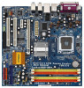
) 5 67 8 CLRCMOS1 CMOS Battery PARALLEL PORT DDRII_4 (64/72 bit, 240-pin module Bottom: CTR BASS ConRoe1333-1394 Dual Core CPU Dual Channel USB 2.0 T: USB2 B: USB3 Top: 1394 USB 2.0 T: DDRII_2, DDRII_4; Orange) 25 Front Panel IEEE 1394 Header 9 South Bridge Controller (FRONT_1394; Red - ASRock ConRoe1333-1394 | User Manual - Page 11
ASRock HD 8CH_1394 I/O 1 14 13 12 2 3 4 7 5 8 6 9 11 10 1 Parallel Port 2 IEEE 1394 Port 3 RJ-45 Port 4 Side Speaker (Gray) 5 Rear Speaker (Black) 6 Central / Bass (Orange) 7 Line In (Light Blue) * 8 Front Speaker (Lime) 9 Microphone (Pink) 10 USB 2.0 Ports (USB01) 11 USB 2.0 Ports - ASRock ConRoe1333-1394 | User Manual - Page 12
Chapter 2 Installation ConRoe1333-1394 is a Micro ATX form factor (9.6" x 9.6", 24.4 x 24.4 cm) motherboard. Before you install the motherboard, study the configuration of your chassis to ensure that the motherboard - ASRock ConRoe1333-1394 | User Manual - Page 13
2.3 CPU Installation For the installation of Intel 775-LAND CPU, please follow the steps below. 775-Pin Socket Overview Before you insert the 775-LAND CPU into the socket, please check if the CPU surface is unclean or if there is any bent pin on the socket. Do not force to insert the CPU into the - ASRock ConRoe1333-1394 | User Manual - Page 14
Pick and Place Cap): Use your left hand index finger and thumb to support the load plate edge, engage PnP cap with right hand thumb and peel the PnP cap. 2. This cap must be placed if returning the motherboard for after service. Step 4. Close the socket: Step 4-1. Rotate the load plate onto the IHS. - ASRock ConRoe1333-1394 | User Manual - Page 15
Pin socket that supports Intel 775- connect the CPU fan to the CPU_FAN connector (CPU_FAN1, see page 10, No. 3). For proper installation, please kindly refer to the instruction manuals Connect fan header with the CPU fan connector on the motherboard. Secure excess cable with tie-wrap to ensure cable - ASRock ConRoe1333-1394 | User Manual - Page 16
2.5 Installation of Memory Modules (DIMM) ConRoe1333-1394 motherboard provides four 240-pin DDRII (Double Data Rate II) DIMM slots, and supports Dual Channel Memory Technology. For dual channel configuration, you always need to install identical (the same brand, speed, size and chip-type) DDRII DIMM - ASRock ConRoe1333-1394 | User Manual - Page 17
only install one memory module, you can install it to any one of the four slots. These two TRANSCEND memory modules can only be supported under the following conditions: DRAM SIZE TYPE CELL CELL NO. SINGLE SIDE / VENDOR (MB) VENDOR DOUBLE SIDE TRANSCEND 256 DDRII533 SAMSUNG K4T56083QF-ZCD5 - ASRock ConRoe1333-1394 | User Manual - Page 18
The DIMM only fits in one correct orientation. It will cause permanent damage to the motherboard and the DIMM if you force the DIMM into the slot at incorrect orientation. Step 3. Firmly insert the DIMM into the slot until the retaining clips at both ends fully snap back in place and the DIMM is - ASRock ConRoe1333-1394 | User Manual - Page 19
2.7 Jumpers Setup The illustration shows how jumpers are setup. When the jumper cap is placed on pins, the jumper is "Short". If no jumper cap is placed on pins, the jumper is "Open". The illustration shows a 3-pin jumper whose pin1 and pin2 are "Short" when jumper cap is placed on these 2 - ASRock ConRoe1333-1394 | User Manual - Page 20
IDE connector (Blue) (39-pin IDE1, see p.10 No. 10) PIN1 IDE1 connect the blue end connect the black end to the motherboard to the IDE devices 80-conductor ATA 66/100 cable Note: Please refer to the instruction of your IDE device vendor for the details. Serial ATAII Connectors (SATAII_1 - ASRock ConRoe1333-1394 | User Manual - Page 21
header can support two USB 2.0 ports. (9-pin cable that allows convenient connection and control of audio devices. 1. High Definition Audio supports Jack Sensing, but the panel wire on the chassis must support HDA to function correctly. Please follow the instruction in our manual and chassis manual - ASRock ConRoe1333-1394 | User Manual - Page 22
a CPU fan cable to this connector and match the black wire to the ground pin. Though this motherboard provides 4-Pin CPU fan (Quiet Fan) support, the 3-Pin CPU fan still can work successfully even without the fan speed control function. If you plan to connect the 3-Pin CPU fan to the CPU fan - ASRock ConRoe1333-1394 | User Manual - Page 23
can support one IEEE 1394 port. HDMI_SPDIF header, providing SPDIF audio output to HDMI VGA card, allows the system to connect HDMI Digital TV/ projector/LCD devices. Please connect the HDMI_SPDIF connector of HDMI VGA card to this header. Please connect the black end (A) of HDMI_SPDIF cable to - ASRock ConRoe1333-1394 | User Manual - Page 24
Graphics slot on this motherboard. For the proper installation of HDMI VGA card, please refer to the installation guide on page 18. Step 2. Connect the black end (A) of HDMI_SPDIF cable to the HDMI_SPDIF header (HDMI_SPDIF1, yellow, see page 10, No. 23) on the motherboard. Make sure to correctly - ASRock ConRoe1333-1394 | User Manual - Page 25
guide. Some default setting of SATAII hard disks may not be at SATAII mode, which operate with the best performance. In order to enable SATAII function, please follow the below instruction 's website for details: http://www.hitachigst.com/hdd/support/download.htm The above examples are just for your - ASRock ConRoe1333-1394 | User Manual - Page 26
the motherboard's SATAII connector. STEP 4: Connect the other end of the SATA data cable to the SATA / SATAII hard disk. 2.12 Driver Installation Guide To install the drivers to your system, please insert the support CD to your optical drive first. Then, the drivers compatible to your system can be - ASRock ConRoe1333-1394 | User Manual - Page 27
Chapter 3 BIOS SETUP UTILITY 3.1 Introduction This section explains how to use the BIOS SETUP UTILITY to configure your system. The BIOS FWH chip on the motherboard stores the BIOS SETUP UTILITY. You may run the BIOS SETUP UTILITY when you start up the computer. Please press during the Power-On - ASRock ConRoe1333-1394 | User Manual - Page 28
Main Advanced H/W Monitor Boot Security Exit System Overview System Time System Date [14:00:09] [Fri 06/22/2007] BIOS Version : ConRoe1333-1394 BIOS P1.00 Processor Type : Intel (R) CPU 3.60 GHz (64bit) Processor Speed : 3600 MHz Microcode Update : F65/7 Cache Size : 4096KB Total - ASRock ConRoe1333-1394 | User Manual - Page 29
BIOS SETUP UTILITY Main Advanced H/W Monitor Boot Security Exit Advanced Settings WARNING : Setting wrong values in below sections may cause system to malfunction. CPU Configuration Chipset Configuration ACPI Configuration IDE Configuration PCIPnP Configuration Floppy Configuration SuperIO - ASRock ConRoe1333-1394 | User Manual - Page 30
option " Intel (R) SpeedStep(tm) tech." in advance. Enhance Halt State All processors support the Halt State (C1). The C1 state is supported through the native processor instructions HLT and MWAIT and requires no hardware support from the chipset. In the C1 power state, the processor maintains the - ASRock ConRoe1333-1394 | User Manual - Page 31
[Enabled]. This item will be hidden if the current CPU does not support Intel (R) SpeedStep(tm) tech.. Please note that enabling this function may ] Primary Graphics Adapter OnBoard HD Audio Front Panel CD-In OnBoard Lan OnBoard 1394 PCI Fix Function VCCM Voltage VDDQ Voltage [PCI] [Auto] [Auto] [ - ASRock ConRoe1333-1394 | User Manual - Page 32
logo test, please disable this option. OnBoard Lan This allows you to enable or disable the "OnBoard Lan" feature. OnBoard 1394 This allows you to enable or disable the "OnBoard 1394" feature. PCI Fix Function This allows you to enable or disable PCI Fix Function. The default value is [Enabled]. If - ASRock ConRoe1333-1394 | User Manual - Page 33
VCCM Voltage Use this to select VCCM Voltage. Configuration options: [High], [Middle], [Low], and [Auto]. The default value of this feature is [Auto]. VDDQ Voltage Configuration options: [High], [Low] and [Auto]. The default value is [Auto]. 33 - ASRock ConRoe1333-1394 | User Manual - Page 34
field allows you to select whether to auto-detect or disable the Suspend-to-RAM feature. Select [Auto] will enable this feature if the system supports it. Restore on AC/Power Loss This allows you to set the power state after an unexpected AC/Power loss. If [Power Off] is selected - ASRock ConRoe1333-1394 | User Manual - Page 35
it is set to [IDE 1, SATA 2, SATA 4], then SATAII_1, SATAII_3 will not work. Because Intel® ICH7 south bridge only supports four IDE devices under legacy OS (Windows NT), you have to choose [SATA 1, SATA 2, SATA 3, SATA 4], [SATA "Primary IDE Master" as the example in the following instruction. 35 - ASRock ConRoe1333-1394 | User Manual - Page 36
Mode DMA Mode S.M.A.R.T. 32Bit Data Transfer :Hard Disk :ST340014A :40.0 GB :Supported :16Sectors :4 :MultiWord DMA-2 :Ultra DMA-5 :Supported [Auto] [Auto] [Auto] [Auto] [Auto] [Disabled] [Enabled] Select the type of device connected to the system. +F1 F9 F10 ESC Select Screen Select Item Change - ASRock ConRoe1333-1394 | User Manual - Page 37
S.M.A.R.T. Use this item to enable or disable the S.M.A.R.T. (Self-Monitoring, Analysis, and Reporting Technology) feature. Configuration options: [Disabled], [Auto], [Enabled]. 32-Bit Data Transfer Use this item to enable 32-bit access to maximize the IDE hard disk data transfer rate. 3.3.5 PCIPnP - ASRock ConRoe1333-1394 | User Manual - Page 38
Floppy A [1.44 MB 312"] Select the type of floppy drive connected to the system. +F1 F9 F10 ESC Select Screen Select Item Change Floppy Controller Serial Port Address Infrared Port Address Parallel Port Address Parallel Port Mode EPP Version ECP Mode DMA Channel Parallel Port IRQ [Enabled] - ASRock ConRoe1333-1394 | User Manual - Page 39
or disable the USB 2.0 support. Legacy USB Support Use this item to enable or disable the support to emulate legacy I/O devices such as mouse, keyboard,... etc. Or you may select [Auto] so that the system will start to auto-detect; if there is no USB device connected, "Auto" option will disable - ASRock ConRoe1333-1394 | User Manual - Page 40
3.4 Hardware Health Event Monitoring Screen In this section, it allows you to monitor the status of the hardware on your system, including the parameters of the CPU temperature, motherboard temperature, CPU fan speed, chassis fan speed, and the critical voltage. BIOS SETUP UTILITY Main Advanced - ASRock ConRoe1333-1394 | User Manual - Page 41
3.5 Boot Screen In this section, it will display the available devices on your system for you to configure the boot settings and the boot priority. Main Advanced BIOS SETUP UTILITY H/W Monitor Boot Security Exit Boot Settings Boot Settings Configuration Configure Settings during System Boot. - ASRock ConRoe1333-1394 | User Manual - Page 42
3.6 Security Screen In this section, you may set or change the supervisor/user password for the system. For the user password, you may also clear it. BIOS SETUP UTILITY Main Advanced H/W Monitor Boot Security Exit Security Settings Supervisor Password : Not Installed User Password : Not - ASRock ConRoe1333-1394 | User Manual - Page 43
3.7 Exit Screen Main BIOS SETUP UTILITY Advanced H/W Monitro Boot Security Exit Exit Options Save Changes and Exit Discard Changes and Exit Discard Changes Load Optimal Defaults Exit system setup after saving the changes. F10 key can be used for this operation. Select Screen Select Item - ASRock ConRoe1333-1394 | User Manual - Page 44
install the necessary drivers to activate the devices. 4.2.3 Utilities Menu The Utilities Menu shows the applications software that the motherboard supports. Click on a specific item then follow the installation wizard to install it. 4.2.4 Contact Information If you need to contact ASRock or want to
-
 1
1 -
 2
2 -
 3
3 -
 4
4 -
 5
5 -
 6
6 -
 7
7 -
8
-
9
-
10
-
11
-
12
-
13
-
14
-
15
-
16
-
17
-
18
-
19
-
20
-
21
-
22
-
23
-
24
-
25
-
26
-
27
-
28
-
29
-
30
-
31
-
32
-
33
-
34
-
35
-
36
-
37
-
38
-
39
-
40
-
41
-
42
-
43
-
44
 |
 |

1
ConRoe1333-1394
User Manual
Version 1.0
Published June 2007
Copyright©2007 ASRock INC. All rights reserved.