ASRock E35LM1 R2.0 User Manual
ASRock E35LM1 R2.0 Manual
 |
View all ASRock E35LM1 R2.0 manuals
Add to My Manuals
Save this manual to your list of manuals |
ASRock E35LM1 R2.0 manual content summary:
- ASRock E35LM1 R2.0 | User Manual - Page 1
E35LM1 R2.0 User Manual Version 1.0 Published October 2012 Copyright©2012 ASRock INC. All rights reserved. 1 - ASRock E35LM1 R2.0 | User Manual - Page 2
any form or by any means, except duplication of documentation by the purchaser for backup purpose, without written consent of ASRock Inc. Products and corporate names appearing in this manual may or may not be registered trademarks or copyrights of their respective companies, and are used only for - ASRock E35LM1 R2.0 | User Manual - Page 3
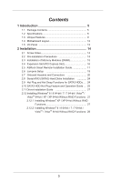
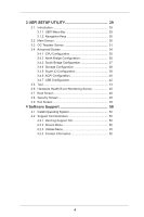
Holes 14 2.2 Pre-installation Precautions 14 2.3 Installation of Memory Modules (DIMM 15 2.4 Expansion Slot (PCI Express Slot 16 2.5 ASRock Smart Remote Installation Guide 17 2.6 Jumpers Setup 19 2.7 Onboard Headers and Connectors 20 2.8 Serial ATA3 (SATA3) Hard Disks Installation 24 2.9 Hot - ASRock E35LM1 R2.0 | User Manual - Page 4
Health Event Monitoring Screen 45 3.7 Boot Screen 46 3.8 Security Screen 48 3.9 Exit Screen 49 4 Software Support 50 4.1 Install Operating System 50 4.2 Support CD Information 50 4.2.1 Running Support CD 50 4.2.2 Drivers Menu 50 4.2.3 Utilities Menu 50 4.2.4 Contact Information 50 4 - ASRock E35LM1 R2.0 | User Manual - Page 5
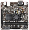
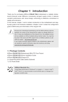
specific information about the model you are using. www.asrock.com/support/index.asp 1.1 Package Contents ASRock E35LM1 R2.0 Motherboard (Mini-ITX Form Factor) ASRock E35LM1 R2.0 Quick Installation Guide ASRock E35LM1 R2.0 Support CD 2 x Serial ATA (SATA) Data Cables (Optional) 1 x I/O Panel Shield - ASRock E35LM1 R2.0 | User Manual - Page 6
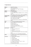
ITX Form Factor - AMD Zacate E-240 APU - Supports AMD's Cool 'n' QuietTM Technology - UMI 2.5 GT/s - AMD A50M Chipset - 2 x DDR3 DIMM slots - Supports 100/1000 Mb/s - Realtek RTL8111E - Supports Wake-On-LAN - Supports LAN Cable Detection - Supports Energy Efficient Ethernet 802.3az - Supports PXE I/O - ASRock E35LM1 R2.0 | User Manual - Page 7
Play" - ACPI 1.1 Compliance Wake Up Events - Supports jumperfree - SMBIOS 2.3.1 Support - DRAM, FCH, +1V, +1.8V Voltage Multi-adjustment Support CD - Drivers, Utilities, AntiVirus Software (Trial Version), CyberLink MediaEspresso 6.5 Trial, ASRock MAGIX Multimedia Suite - OEM, Google Chrome - ASRock E35LM1 R2.0 | User Manual - Page 8
less than 4GB for the reservation for system usage under Windows® 8 / 7 / VistaTM / XP. For Windows® OS with 64-bit CPU, there is no such limitation. 2. ASRock XFast RAM is not supported by Microsoft® Windows® XP 64-bit. 8 - ASRock E35LM1 R2.0 | User Manual - Page 9
it makes your iPhone charge much quickly from your computer and up to 40% faster than before. ASRock APP Charger allows you to quickly charge many Apple devices simultaneously and even supports continuous charging when your PC enters into Standby mode (S1), Suspend to RAM (S3), hibernation mode (S4 - ASRock E35LM1 R2.0 | User Manual - Page 10
regaining power. Please note that BIOS files need to be placed in the root directory of your USB disk. Only USB2.0 ports support this feature. ASRock OMG (Online Management Guard) Administrators are able to establish an internet curfew or restrict internet access at specified times via OMG. You - ASRock E35LM1 R2.0 | User Manual - Page 11
the PC next time. Just simply enable this function; the PC will be assured to access the UEFI directly in the very beginning. ASRock Good Night LED ASRock Good Night LED technology can offer you a better environment by extinguishing the unessential LED. By enabling Good Night LED in BIOS, the Power - ASRock E35LM1 R2.0 | User Manual - Page 12
240-FpinSBmo8d0ul0e) CPU_FAN1 VGA1 Dx11 RoHS 1 SATA3 6Gb/s 23 22 21 Top: LINE IN Center: FRONT Bottom: MIC IN Super IO USB 2.0 T: USB4 B: USB5 Top: RJ-45 LAN PHY HD_AUDIO1 AUDIO CODEC 1 COM1 USB6_7 1 USB8_9 1 1 CIR1 E35LM1 ) 22 COM Port Header (COM1) 23 AMD A50M Chipset 12 - ASRock E35LM1 R2.0 | User Manual - Page 13
1.5 I/O Panel 1 2 3 4 5 6 8 7 1 PS/2 Keyboard/Mouse Port (Purple/Green) 2 VGA Port * 3 LAN RJ-45 Port 4 Line In (Light Blue) ** 5 Front Speaker (Lime) 6 Microphone (Pink) 7 USB 2.0 Ports (USB45) 8 USB 2.0 Ports (USB01) * There are two LED next to the LAN port. Please refer to the table below - ASRock E35LM1 R2.0 | User Manual - Page 14
Chapter 2: Installation This is a Mini-ITX form factor motherboard. Before you install the motherboard, study the configuration of your chassis to ensure that the motherboard fits into it. Make sure to - ASRock E35LM1 R2.0 | User Manual - Page 15
2.3 Installation of Memory Modules (DIMM) E35LM1 R2.0 motherboard provides two 240-pin DDR3 (Double Data Rate 3) DIMM slots. It is not allowed to install a DDR or DDR2 memory module into DDR3 slot; otherwise, this motherboard and - ASRock E35LM1 R2.0 | User Manual - Page 16
2.4 Expansion Slot (PCI Express Slot) There is 1 PCI Express slot on this motherboard. PCIE slot: PCIE1 (PCIE x16 slot) is used for PCI Express x4 lane width graphics cards. Installing an expansion card Step 1. Before installing the expansion card, please make sure that the power supply is switched - ASRock E35LM1 R2.0 | User Manual - Page 17
option, please shut down your system and install Multi-Angle CIR Receiver to the other front USB port then try again. Step5. Enter Windows. Execute ASRock support CD and install CIR Driver. (It is listed at the bottom of driver list.) 17 - ASRock E35LM1 R2.0 | User Manual - Page 18
chassis on the market. 3. The Multi-Angle CIR Receiver does not support Hot-Plug function. Please install it before you boot the system. * ASRock Smart Remote is only supported by some of ASRock motherboards. Please refer to ASRock website for the motherboard support list: http://www.asrock.com 18 - ASRock E35LM1 R2.0 | User Manual - Page 19
, and then shut it down before you do the clear-CMOS ac- tion. Please be noted that the password, date, time, user default profile, 1394 GUID and MAC address will be cleared only if the CMOS battery is removed. If you clear the CMOS, the case open may be detected. Please - ASRock E35LM1 R2.0 | User Manual - Page 20
USB_PWR Consumer Infrared Module Header (4-pin CIR1) (see p.12 No. 18) SATA3_1 SATA3_2 SATA3_3 SATA3_4 These four Serial ATA3 (SATA3) connectors support SATA data cables for internal storage devices. The current SATA3 interface allows up to 6.0 Gb/s data transfer rate. Either end of the SATA - ASRock E35LM1 R2.0 | User Manual - Page 21
allows convenient connection and control of audio devices. 1. High Definition Audio supports Jack Sensing, but the panel wire on the chassis must support HDA to function correctly. Please follow the instruction in our manual and chassis manual to install your system. 2. If you use AC'97 audio - ASRock E35LM1 R2.0 | User Manual - Page 22
the chassis speaker to this header. Please connect the fan cables to the fan connectors and match the black wire to the ground pin. CHA_FAN2 supports fan speed control by fan power voltage. Please connect the CPU fan cable to the connector and match the black wire to the ground pin - ASRock E35LM1 R2.0 | User Manual - Page 23
along with Pin 1 and Pin 13. 20-Pin ATX Power Supply Installation 1 13 Serial port Header (9-pin COM1) (see p.12 No. 22) This COM1 header supports a serial port module. Chassis Intrusion Header (2-pin CI1) (see p.12 No. 14) 1 GND Signal This motherboard - ASRock E35LM1 R2.0 | User Manual - Page 24
2.8 Serial ATA3 (SATA3) Hard Disks Installation This motherboard adopts AMD A50M chipset that supports Serial ATA3 (SATA3) hard disks. You may install SATA3 hard disks on this motherboard for internal storage devices. This section will guide you to install the SATA3 hard disks. STEP 1: Install the - ASRock E35LM1 R2.0 | User Manual - Page 25
is installed into system properly. The latest SATA3 driver is available on our support website: www.asrock.com 4. Make sure to use the SATA power cable & data cable, which are from our motherboard package. 5. Please follow below instructions step by step to reduce the risk of HDD crash or data loss - ASRock E35LM1 R2.0 | User Manual - Page 26
data cable to the SATA3 HDD. How to Hot Unplug a SATA3 HDD: Points of attention, before you process the Hot Unplug: Please do follow below instruction sequence to process the Hot Unplug, improper procedure will cause the SATA3 HDD damage and data loss. Step 1 Unplug SATA data cable from SATA3 HDD - ASRock E35LM1 R2.0 | User Manual - Page 27
2.11 Driver Installation Guide To install the drivers to your system, please insert the support CD to your optical drive first. Then, the drivers compatible to your system can be auto-detected and listed on the support CD driver page. Please follow the order from up to bottom side to install those - ASRock E35LM1 R2.0 | User Manual - Page 28
2.12.2 Installing Windows® 8 / 8 64-bit / 7 / 7 64-bit / VistaTM / VistaTM 64-bit Without RAID Functions If you want to install Windows® 8 / 8 64-bit / 7 / 7 64-bit / VistaTM / VistaTM 64-bit OS on your SATA3 HDDs without RAID functions, please follow below steps. Using SATA3 HDDs with NCQ function - ASRock E35LM1 R2.0 | User Manual - Page 29
SETUP UTILITY when you start up the computer. Please press or during the Power-On-Self-Test (POST) to enter the UEFI SETUP UTILITY, otherwise, POST will continue with its test routines. If you wish to enter the UEFI SETUP UTILITY after POST, restart the system by pressing + - ASRock E35LM1 R2.0 | User Manual - Page 30
3.1.2 Navigation Keys Please check the following table for the function description of each navigation key. Navigation Key(s) Function Description / Moves cursor left or right to select Screens / Moves cursor up or down to select items + / - To change option for the selected items - ASRock E35LM1 R2.0 | User Manual - Page 31
3.3 OC Tweaker Screen In the OC Tweaker screen, you can set up overclocking features. DRAM Timing Configuration DRAM Frequency If [Auto] is selected, the motherboard will detect the memory module(s) inserted and assigns appropriate frequency automatically. DRAM Timing Control Power Saving Mode Use - ASRock E35LM1 R2.0 | User Manual - Page 32
default is [Auto]. RAS# Active Time (tRAS) Use this item to change RAS# Active Time (tRAS) Auto/Manual setting. The default is [Auto]. Command Rate (CR) Use this item to change Command Rate (CR) Auto/Manual setting. Min: 1N. Max: 2N. The default is [Auto]. RAS# Cycle Time (tRC) Use this item - ASRock E35LM1 R2.0 | User Manual - Page 33
Voltage Configuration DRAM Voltage Use this to select DRAM Voltage. The default value is [Auto]. FCH Voltage Use this to select FCH Voltage. The default value is [Auto]. +1.8V Voltage Use this to select +1.8V Voltage. The default value is [Auto]. +1V Voltage Use this to select +1V Voltage. The - ASRock E35LM1 R2.0 | User Manual - Page 34
3.4 Advanced Screen In this section, you may set the configurations for the following items: CPU Configuration, North Bridge Configuration, South Bridge Configuration, Storage Configuration, Super IO Configuration, ACPI Configuration and USB Configuration. Setting wrong values in this section may - ASRock E35LM1 R2.0 | User Manual - Page 35
Machine) architecture. When this option is set to [Enabled], a VMM (Virtual Machine Architecture) can utilize the additional hardware capabilities provided by AMD-V. Configuration options: [Enabled] and [Disabled]. The default value is [Enabled]. C6 Mode Use this to enable or disable CPU C6 state - ASRock E35LM1 R2.0 | User Manual - Page 36
3.4.2 North Bridge Configuration Primary Graphics Adapter This item allows you to select the type of Primary VGA in case of multiple video controllers. The default value of this feature is [PCI Express]. Cofiguration options: [Onboard] and [PCI Express]. Share Memory This allows you to set onboard - ASRock E35LM1 R2.0 | User Manual - Page 37
3.4.3 South Bridge Configuration Onboard HD Audio Select [Enabled] or [Disabled] for the onboard HD Audio feature. The default value is [Enabled]. Front Panel Select [Auto] or [Disabled] for the onboard HD Audio Front Panel. Onboard LAN This allows you to enable or disable the "Onboard LAN" - ASRock E35LM1 R2.0 | User Manual - Page 38
this to select SATA mode. Configuration options: [IDE Mode] and [AHCI Mode]. The default value is [AHCI Mode]. AHCI (Advanced Host Controller Interface) supports NCQ and other new features that will improve SATA disk performance but IDE mode does not have these advantages. SATA Aggressive Link Power - ASRock E35LM1 R2.0 | User Manual - Page 39
3.4.5 Super IO Configuration Serial Port Use this item to enable or disable the onboard serial port. Serial Port Address Use this item to set the address for the onboard serial port. Configuration options: [3F8h / IRQ4] and [3E8h / IRQ4]. CIR Controller Use this item to enable or disable CIR - ASRock E35LM1 R2.0 | User Manual - Page 40
RAM Use this item to select whether to auto-detect or disable the Suspend-toRAM feature. Select [Auto] will enable this feature if the OS supports it. Check Ready Bit Use this item to enable or disable the feature Check Ready Bit. ACPI HPET Table Use this item to enable or - ASRock E35LM1 R2.0 | User Manual - Page 41
CSM Please disable CSM when you enable Fast Boot option. The default value is [Enabled]. 41 - ASRock E35LM1 R2.0 | User Manual - Page 42
to below descriptions for the details of these four options: [Enabled] - Enables support for legacy USB. [Auto] - Enables legacy support if USB devices are connected. [Disabled] - USB devices are not allowed to use ] - USB devices are allowed to use only under UEFI setup and Windows / Linux OS. 42 - ASRock E35LM1 R2.0 | User Manual - Page 43
3.5 Tool System Browser System Browser can let you easily check your current system configuration in UEFI setup. OMG(Online Management Guard) Administrators are able to establish an internet curfew or restrict internet access at specified times via OMG. You may schedule the starting and ending hours - ASRock E35LM1 R2.0 | User Manual - Page 44
enable this function. Network Configuration Internet Setting Use this item to set up the internet connection mode. Configuration options: [DHCP (Auto IP)] and [PPPOE]. UEFI Download Server Use this item to select UEFI firmware download server for Internet Flash. Configuration options: [Asia], [ - ASRock E35LM1 R2.0 | User Manual - Page 45
Mode]. The default is value [Full On]. Chassis Fan 1 Setting This allows you to set the chassis fan 1 speed. Configuration options: [Full On] and [Manual Mode]. The default is value [Full On]. Chassis Fan 2 Setting This allows you to set the chassis fan 2 speed. Configuration options: [Full On] and - ASRock E35LM1 R2.0 | User Manual - Page 46
using an USB flash drive. [Ultra Fast] - There are a few restrictions. 1. Only supports Windows® 8 UEFI operating system. 2. You will not be able to enter BIOS Setup ( 3. If you are using an external graphics card, the VBIOS must support UEFI GOP in order to boot. Boot From Onboard LAN Use this - ASRock E35LM1 R2.0 | User Manual - Page 47
Full Screen Logo Use this item to enable or disable OEM Logo. The default value is [Enabled]. AddOn ROM Display Use this option to adjust AddOn ROM Display. If you enable the option "Full Screen Logo" but you want to see the AddOn ROM information when the system boots, please select [Enabled]. - ASRock E35LM1 R2.0 | User Manual - Page 48
3.8 Security Screen In this section, you may set or change the supervisor/user password for the system. For the user password, you may also clear it. Secure Boot Use this to enable or disable Secure Boot. The default value is [Disabled]. 48 - ASRock E35LM1 R2.0 | User Manual - Page 49
3.9 Exit Screen Save Changes and Exit When you select this option, it will pop-out the following message, "Save configuration changes and exit setup?" Select [OK] to save the changes and exit the UEFI SETUP UTILITY. Discard Changes and Exit When you select this option, it will pop-out the following - ASRock E35LM1 R2.0 | User Manual - Page 50
applications software that the motherboard supports. Click on a specific item then follow the installation wizard to install it. 4.2.4 Contact Information If you need to contact ASRock or want to know more about ASRock, welcome to visit ASRock's website at http://www.asrock.com; or you may contact - ASRock E35LM1 R2.0 | User Manual - Page 51
POST and choose the item "UEFI:xxx" to boot. 4. Start Windows® installation. 5. If you install Windows® 7 64-bit OS, OS will be formatted by GPT (GUID Partition Table). Please install the hotfix file from Microsoft®: http://support.microsoft.com/kb/979903 51
-
 1
1 -
 2
2 -
 3
3 -
 4
4 -
 5
5 -
 6
6 -
 7
7 -
8
-
9
-
10
-
11
-
12
-
13
-
14
-
15
-
16
-
17
-
18
-
19
-
20
-
21
-
22
-
23
-
24
-
25
-
26
-
27
-
28
-
29
-
30
-
31
-
32
-
33
-
34
-
35
-
36
-
37
-
38
-
39
-
40
-
41
-
42
-
43
-
44
-
45
-
46
-
47
-
48
-
49
-
50
-
51
 |
 |

1
E35LM1 R2.0
User Manual
Version 1.0
Published October 2012
Copyright©2012 ASRock INC. All rights reserved.