ASRock E35LM1 User Manual
ASRock E35LM1 Manual
 |
View all ASRock E35LM1 manuals
Add to My Manuals
Save this manual to your list of manuals |
ASRock E35LM1 manual content summary:
- ASRock E35LM1 | User Manual - Page 1
E35LM1 User Manual Version 1.0 Published March 2012 Copyright©2012 ASRock INC. All rights reserved. 1 - ASRock E35LM1 | User Manual - Page 2
purchaser for backup purpose, without written consent of ASRock Inc. Products and corporate names appearing in this manual may or may not be registered trademarks or copyrights , USA ONLY The Lithium battery adopted on this motherboard contains Perchlorate, a toxic substance controlled in Perchlorate - ASRock E35LM1 | User Manual - Page 3
Plug Feature and Operation Guide 24 2.11 Driver Installation Guide 26 2.12 Installing Windows® 7 / 7 64-bit / VistaTM / VistaTM 64-bit / XP / XP 64-bit Without RAID Functions 26 2.12.1 Installing Windows® XP / XP 64-bit Without RAID Functions 26 2.12.2 Installing Windows® 7 / 7 64-bit / VistaTM - ASRock E35LM1 | User Manual - Page 4
Health Event Monitoring Screen 42 3.6 Boot Screen 43 3.7 Security Screen 44 3.8 Exit Screen 45 4 Software Support 46 4.1 Install Operating System 46 4.2 Support CD Information 46 4.2.1 Running Support CD 46 4.2.2 Drivers Menu 46 4.2.3 Utilities Menu 46 4.2.4 Contact Information 46 4 - ASRock E35LM1 | User Manual - Page 5
Package Contents ASRock E35LM1 Motherboard (Mini-ITX Form Factor: 6.7-in x 6.7-in, 17.0 cm x 17.0 cm) ASRock E35LM1 Quick Installation Guide ASRock E35LM1 Support CD 2 x Serial ATA (SATA) Data Cables (Optional) 1 x I/O Panel Shield ASRock Reminds You... To get better performance in Windows® 7 / 7 64 - ASRock E35LM1 | User Manual - Page 6
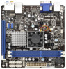
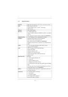
Memory Expansion Slot Graphics Audio LAN Rear Panel I/O SATA3 Connector - Mini-ITX Form Factor: 6.7-in x 6.7-in, 17.0 cm x 17.0 cm - AMD Zacate E-240 APU - Supports AMD's Cool 'n' QuietTM Technology - UMI 2.5 GT/s - AMD A50M Chipset - 2 x DDR3 DIMM slots - Supports Gb/s connectors, support NCQ, AHCI - ASRock E35LM1 | User Manual - Page 7
BIOS with GUI support - Supports "Plug and Play" - ACPI 1.1 Compliance Wake Up Events - Supports jumperfree - SMBIOS 2.3.1 Support - DRAM, FCH, +1V, +1.8V Voltage Multi-adjustment Support CD - Drivers, Utilities, AntiVirus Software (Trial Version), CyberLink MediaEspresso 6.5 Trial, ASRock - ASRock E35LM1 | User Manual - Page 8
output, this motherboard supports 2-channel, 4-channel, 6-channel, and 8-channel modes. Please check the table on page 12 for proper connection. 4. ASRock Instant Flash is a BIOS flash utility embedded in Flash ROM. This convenient BIOS update tool allows you to update system BIOS without entering - ASRock E35LM1 | User Manual - Page 9
fear of failing. If power loss occurs during the BIOS update process, ASRock Crashless BIOS will automatically finish the BIOS update procedure after regaining power. Please note that BIOS files need to be placed in the root directory of your USB disk. Only USB2.0 ports support this feature. 11 - ASRock E35LM1 | User Manual - Page 10
and the heatsink when you install the PC system. 14. ASRock XFast RAM is not supported by Microsoft® Windows® XP / XP 64-bit. 15. EuP stands for Energy Using Product, was a provision regulated by the European Union to define the power consumption for the completed system. According to EuP, the total - ASRock E35LM1 | User Manual - Page 11
Motherboard Layout USB 2.0 T: USB0 B: USB1 12 34 17.0cm (6.7 in) E35LM1 CHA_FAN1 5 DDR3 CMOS Battery PS2 Keyboard/Mouse 6 CLRCMOS1 1 17.0cm (6.7 in) SATA3 6Gb/s DDR3_A1 (64 bit, 240-FpinSBmo8d0ul0e) DDR3_A2 (64 bit, 240 (HD_AUDIO1, White) 21 COM Port Header (COM1) 22 AMD A50M Chipset 11 - ASRock E35LM1 | User Manual - Page 12
1.4 I/O Panel 1 2 3 47 58 6 9 11 10 1 PS/2 Keyboard/Mouse Port (Purple/Green) 2 VGA Port * 3 LAN RJ-45 Port 4 Central / Bass (Orange) 5 Rear Speaker (Black) 6 Optical SPDIF Out Port 7 Line In (Light Blue) ** 8 Front Speaker (Lime) 9 Microphone (Pink) 10 USB 2.0 Ports (USB45) 11 USB 2.0 - ASRock E35LM1 | User Manual - Page 13
To enable Multi-Streaming function, you need to connect a front panel audio cable to the front panel audio header. After restarting your computer, you will find "Mixer" tool on your system. Please select "Mixer ToolBox" , click "Enable playback multi-streaming", and click "ok". Choose "2CH", "4CH - ASRock E35LM1 | User Manual - Page 14
This is a Mini-ITX form factor (6.7" x 6.7", 17.0 x 17.0 cm) motherboard. Before you install the motherboard, study the configuration of your chassis to ensure that the motherboard fits into it. Make sure to unplug the power cord before installing or removing the motherboard. Failure to do - ASRock E35LM1 | User Manual - Page 15
of Memory Modules (DIMM) E35LM1 motherboard provides two 240-pin DDR3 (Double Data Rate 3) DIMM slots. It is not allowed to install a DDR or DDR2 memory module into DDR3 slot; otherwise, this motherboard and DIMM may be damaged. Installing a DIMM Please make sure to disconnect power supply - ASRock E35LM1 | User Manual - Page 16
PCI Express slot on this motherboard. PCIE slot: PCIE1 (PCIE x16 slot; Blue) is used for PCI Express x4 lane width graphics cards. Installing an expansion card Step 1. Before installing the expansion card, please make sure that the power supply is switched off or the power cord is unplugged. Please - ASRock E35LM1 | User Manual - Page 17
find this option, please shut down your system and install Multi-Angle CIR Receiver to the other front USB port then try again. Step5. Enter Windows. Execute ASRock support CD and install CIR Driver. (It is listed at the bottom of - ASRock E35LM1 | User Manual - Page 18
chassis on the market. 3. The Multi-Angle CIR Receiver does not support Hot-Plug function. Please install it before you boot the system. * ASRock Smart Remote is only supported by some of ASRock motherboards. Please refer to ASRock website for the motherboard support list: http://www.asrock.com 18 - ASRock E35LM1 | User Manual - Page 19
setup, please turn off the computer and unplug the power cord from the power supply. After waiting for 15 seconds, use a jumper cap to short pin2 and pin3 on CLRCMOS1 for 5 seconds. However, please do not clear the CMOS right after you update the BIOS. If you need to clear the CMOS when you - ASRock E35LM1 | User Manual - Page 20
) 1 GND IRTX IRRX ATX+5VSB Besides four default USB 2.0 ports on the I/O panel, there are two USB 2.0 headers on this motherboard. Each USB 2.0 header can support two USB 2.0 ports. This header can be used to connect the remote controller receiver. Front Panel Audio Header (9-pin HD_AUDIO1) (see - ASRock E35LM1 | User Manual - Page 21
Jack Sensing, but the panel wire on the chassis must support HDA to function correctly. Please follow the instruction in our manual and chassis manual to install your system. 2. If you use AC'97 audio panel, please install it to the front panel audio header as below: A. Connect Mic_IN (MIC) - ASRock E35LM1 | User Manual - Page 22
CPU fan cable to the connector and match the black wire to the ground pin. CPU_FAN1 supports fan speed control. Please connect an ATX power supply to this connector. 1 13 Though this motherboard provides 24-pin ATX power connector, 12 24 it can still work if you adopt a traditional 20-pin ATX - ASRock E35LM1 | User Manual - Page 23
2.8 Serial ATA3 (SATA3) Hard Disks Installation This motherboard adopts AMD A50M chipset that supports Serial ATA3 (SATA3) hard disks. You may install SATA3 hard disks on this motherboard for internal storage devices. This section will guide you to install the SATA3 hard disks. STEP 1: Install the - ASRock E35LM1 | User Manual - Page 24
installed into system properly. The latest SATA / SATAII / SATA3 driver is available on our support website: www.asrock.com 4. Make sure to use the SATA power cable & data cable, which are from our motherboard package. 5. Please follow below instructions step by step to reduce the risk of HDD crash - ASRock E35LM1 | User Manual - Page 25
do follow below instruction sequence to process the Hot Plug, improper procedure will cause the SATA / SATAII / SATA3 HDD damage and data loss. Step 1 Please connect SATA power cable 1x4-pin end Step 2 (White) to the power supply 1x4-pin cable. Connect SATA data cable to the motherboard's SATAII - ASRock E35LM1 | User Manual - Page 26
and listed on the support CD driver page. Please follow the order from up to bottom side to install those required drivers. Therefore, the drivers you install can work properly. 2.12 Installing Windows® 7 / 7 64-bit / VistaTM / VistaTM 64-bit / XP / XP 64-bit Without RAID Functions If you want - ASRock E35LM1 | User Manual - Page 27
Using SATA / SATAII / STA3 HDDs without NCQ function STEP 1: Set up UEFI. A. Enter UEFI SETUP UTILITY Advanced screen Storage Configuration. B. Set the option "SATA Mode" to [IDE]. STEP 2: Install Windows® 7 / 7 64-bit / VistaTM / VistaTM 64-bit OS on your system. 27 - ASRock E35LM1 | User Manual - Page 28
motherboard stores the UEFI SETUP UTILITY. You may run the UEFI SETUP UTILITY when you start up the computer. Please press or during the Power-On-Self-Test back on. Because the UEFI software is constantly being updated, the following UEFI setup screens and descriptions are for reference - ASRock E35LM1 | User Manual - Page 29
3.1.2 Navigation Keys Please check the following table for the function description of each navigation key. Navigation Key(s) Function Description / Moves cursor left or right to select Screens / Moves cursor up or down to select items + / - To change option for the selected items - ASRock E35LM1 | User Manual - Page 30
Configuration DRAM Frequency If [Auto] is selected, the motherboard will detect the memory module(s) inserted and assigns appropriate frequency automatically. DRAM Timing Control Power Saving Mode Use this to enable or disable Power Saving Mode. The default value is [Disabled]. Bank Interleaving - ASRock E35LM1 | User Manual - Page 31
to Read Delay (tWTR) Auto/Manual setting. The default is [Auto]. Read to Precharge (tRTP) Use this item to change Read to Precharge (tRTP) Auto/Manual setting. The default is [Auto]. Four Activate Window (tFAW) Use this item to change Four Activate Window (tFAW) Auto/Manual setting. The default is - ASRock E35LM1 | User Manual - Page 32
Voltage Configuration DRAM Voltage Use this to select DRAM Voltage. The default value is [Auto]. FCH Voltage Use this to select FCH Voltage. The default value is [Auto]. +1.8V Voltage Use this to select +1.8V Voltage. The default value is [Auto]. +1V Voltage Use this to select +1V Voltage. The - ASRock E35LM1 | User Manual - Page 33
to malfunction. Instant Flash Instant Flash is a UEFI flash utility embedded in Flash ROM. This convenient UEFI update tool allows you to update system UEFI without entering operating systems first like MS-DOS or Windows®. Just save the new UEFI file to your USB flash drive, floppy disk or hard drive and - ASRock E35LM1 | User Manual - Page 34
]. If you install Windows® 7 / VistaTM and want to enable this function, please set this item to [Enabled]. Please note that enabling this function may reduce CPU voltage and memory frequency, and lead to system stability or compatibility issue with some memory modules or power supplies. Please set - ASRock E35LM1 | User Manual - Page 35
Primary VGA in case of multiple video controllers. The default value of this feature is [PCI Express]. Cofiguration options: [PCI] and [PCI Express]. Share Memory This allows you to set onboard VGA share memory feature. The default value is [Auto]. 35 - ASRock E35LM1 | User Manual - Page 36
or disable the "Onboard LAN" feature. Restore on AC/Power Loss This allows you to set the power state after an unexpected AC/power loss. If [Power Off] is selected, the AC/power remains off when the power recovers. If [Power On] is selected, the AC/power resumes and the system starts to boot up when - ASRock E35LM1 | User Manual - Page 37
to select SATA mode. Configuration options: [IDE Mode] and [AHCI Mode]. The default value is [AHCI Mode]. AHCI (Advanced Host Controller Interface) supports NCQ and other new features that will improve SATA disk performance but IDE mode does not have these advantages. Aggressive Link PM Capability - ASRock E35LM1 | User Manual - Page 38
3.4.5 Super IO Configuration Serial Port Use this item to enable or disable the onboard serial port. Serial Port Address Use this item to set the address for the onboard serial port. Configuration options: [3F8h / IRQ4] and [3E8h / IRQ4]. CIR Controller Use this item to enable or disable CIR - ASRock E35LM1 | User Manual - Page 39
-toRAM feature. Select [Auto] will enable this feature if the OS supports it. Check Ready Bit Use this item to enable or disable the feature to [Enabled] if you plan to use this motherboard to submit Windows® VistaTM certification. PS/2 Keyboard Power On Use this item to enable or disable PS/2 - ASRock E35LM1 | User Manual - Page 40
OMG (Online Management Guard) Administrators are able to establish an internet curfew or restrict internet access at specified times via OMG. You may choose from [Everyday], [Day of the week] or [Weekdays and weekends], then schedule the starting and ending hours of internet access granted to other - ASRock E35LM1 | User Manual - Page 41
to below descriptions for the details of these four options: [Enabled] - Enables support for legacy USB. [Auto] - Enables legacy support if USB devices are connected. [Disabled] - USB devices are not allowed to Only] - USB devices are allowed to use only under UEFI setup and Windows / Linux OS. 41 - ASRock E35LM1 | User Manual - Page 42
on your system, including the parameters of the CPU temperature, motherboard temperature, CPU fan speed, chassis fan speed, and the critical to set the chassis fan 1 speed. Configuration options: [Full On] and [Manual Mode]. The default is value [Full On]. Chassis Fan 2 Setting This allows you - ASRock E35LM1 | User Manual - Page 43
3.6 Boot Screen In this section, it will display the available devices on your system for you to configure the boot settings and the boot priority. Setup Prompt Timeout This shows the number of seconds to wait for setup activation key. 65535(0XFFFF) means indefinite waiting. Bootup Num-Lock If this - ASRock E35LM1 | User Manual - Page 44
3.7 Security Screen In this section, you may set or change the supervisor/user password for the system. For the user password, you may also clear it. 44 - ASRock E35LM1 | User Manual - Page 45
3.6 Exit Screen Save Changes and Exit When you select this option, the following message "Save configuration changes and exit setup?" will pop-out. Select [Yes] to save the changes and exit the UEFI SETUP UTILITY. Discard Changes and Exit When you select this option, the following message "Discard - ASRock E35LM1 | User Manual - Page 46
install the necessary drivers to activate the devices. 4.2.3 Utilities Menu The Utilities Menu shows the applications software that the motherboard supports. Click on a specific item then follow the installation wizard to install it. 4.2.4 Contact Information If you need to contact ASRock or want to - ASRock E35LM1 | User Manual - Page 47
HDD Larger Than 2TB This motherboard is adopting UEFI BIOS that allows Windows® OS to be installed on a large size HDD (>2TB). Please follow below procedure to install the operating system. 1. Please make sure to use Windows® VistaTM 64-bit (with SP1 or above) or Windows® 7 64-bit. 2. Press or
-
 1
1 -
 2
2 -
 3
3 -
 4
4 -
 5
5 -
 6
6 -
 7
7 -
8
-
9
-
10
-
11
-
12
-
13
-
14
-
15
-
16
-
17
-
18
-
19
-
20
-
21
-
22
-
23
-
24
-
25
-
26
-
27
-
28
-
29
-
30
-
31
-
32
-
33
-
34
-
35
-
36
-
37
-
38
-
39
-
40
-
41
-
42
-
43
-
44
-
45
-
46
-
47
 |
 |

1
E35LM1
User Manual
Version 1.0
Published March 2012
Copyright©2012 ASRock INC. All rights reserved.