ASRock FM2A75 Pro4 Quick Installation Guide
ASRock FM2A75 Pro4 Manual
 |
View all ASRock FM2A75 Pro4 manuals
Add to My Manuals
Save this manual to your list of manuals |
ASRock FM2A75 Pro4 manual content summary:
- ASRock FM2A75 Pro4 | Quick Installation Guide - Page 1
, please follow the related regulations in advance. "Perchlorate Material-special handling may apply, see www.dtsc.ca.gov/hazardouswaste/perchlorate" ASRock Website: http://www.asrock.com Published August 2012 Copyright©2012 ASRock INC. All rights reserved. 1 ASRock FM2A75 Pro4 Motherboard English - ASRock FM2A75 Pro4 | Quick Installation Guide - Page 2
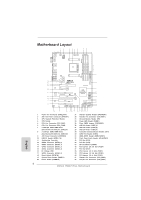
: Top: CHA_FAN3 USB3_7_8 CHA_FAN2 PCIE1 FM2A75 Pro4 Dual Graphics PCIE2 DX11 PCIE3 CMOS BATTERY PCI1 ErP/EuP Ready X Fast USB PCIE4 CLRCMOS1 1 Front USB 3.0 AMD A75 FCH (Hudson-D3) Chipset SATA3_2 SATA3_4 HDMI_SPDIF1 1 PCI2 RoHS 64Mb BIOS PCI3 COM1 1 USB3_4 1 1 CIR1 USB5_6 - ASRock FM2A75 Pro4 | Quick Installation Guide - Page 3
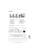
17 USB 3.0 Ports (USB12) 9 Line In (Light Blue) * It is recommended to install the USB Keyboard/Mouse cable to USB 2.0 ports (USB01) instead of USB 3.0 10) (No. 7) (No. 6) Side Speaker (No. 9) 2 V -- -- -- 4 V V -- -- 6 V V V -- 8 V V V V 3 ASRock FM2A75 Pro4 Motherboard - ASRock FM2A75 Pro4 | Quick Installation Guide - Page 4
Primary output" to use Rear Speaker, Central/Bass, and Front Speaker, or select "Realtek HDA Audio 2nd output" to use front panel audio. **** eSATA3 connector supports SATA Gen3 in cable 1M. English 4 ASRock FM2A75 Pro4 Motherboard - ASRock FM2A75 Pro4 | Quick Installation Guide - Page 5
Contents ASRock FM2A75 Pro4 Motherboard (ATX Form Factor: 12.0-in x 8.8-in, 30.5 cm x 22.4 cm) ASRock FM2A75 Pro4 Quick Installation Guide ASRock FM2A75 Pro4 Support CD 4 x Serial ATA (SATA) Data Cables (Optional) 1 x I/O Panel Shield ASRock Reminds You... To get better performance in Windows - ASRock FM2A75 Pro4 | Quick Installation Guide - Page 6
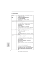
fications Platform CPU Chipset Memory Expansion Slot Graphics 6 - ATX Form Factor: 12.0-in x 8.8-in, 30.5 cm x 22.4 cm - All Solid Capacitor design - Support for Socket FM2 100W processors - 4 + 2 Power Phase Design - Supports AMD's Cool 'n' QuietTM Technology - UMI-Link GEN2 - AMD A75 FCH (Hudson - ASRock FM2A75 Pro4 | Quick Installation Guide - Page 7
5Gb/s - 1 x Front USB 3.0 header (supports 2 USB 3.0 ports) by AMD A75 FCH (Hudson-D3), supports USB 1.1/2.0/3.0 up to 5Gb/s - 5 x SATA3 6.0Gb/s connectors - 1 x IR header - 1 x CIR header - 1 x COM port header - 1 x HDMI_SPDIF header - 1 x Power LED header 7 ASRock FM2A75 Pro4 Motherboard English - ASRock FM2A75 Pro4 | Quick Installation Guide - Page 8
- Microsoft® Windows® 7 / 7 64-bit / VistaTM / VistaTM 64-bit / XP SP3 compliant Certifications - FCC, CE, WHQL - ErP/EuP Ready (ErP/EuP ready power supply is required) * For detailed product information, please visit our website: http://www.asrock.com English 8 ASRock FM2A75 Pro4 Motherboard - ASRock FM2A75 Pro4 | Quick Installation Guide - Page 9
the memory that Windows® cannot use. 3. xvYCC and Deep Color are only supported under Windows® 7 64-bit / 7. Deep Color mode will be enabled only if the display supports 12bpc in EDID. HBR is supported under Windows® 7 64-bit / 7 / VistaTM 64-bit / VistaTM. 9 ASRock FM2A75 Pro4 Motherboard English - ASRock FM2A75 Pro4 | Quick Installation Guide - Page 10
your USB flash drive, floppy disk or hard drive, then you can update your BIOS only in a few clicks without preparing an additional floppy diskette or other complicated flash utility. Please be noted that the USB flash drive or hard drive must use FAT32/16/12 file system. 10 ASRock FM2A75 Pro4 Motherboard - ASRock FM2A75 Pro4 | Quick Installation Guide - Page 11
visited websites, making web surfing faster than ever. And it also boosts the speed of Adobe Photoshop 5 times faster. Another advantage of ASRock XFast RAM is that it reduces the frequency of accessing your SSDs or HDDs in order to extend their lifespan. 11 ASRock FM2A75 Pro4 Motherboard English - ASRock FM2A75 Pro4 | Quick Installation Guide - Page 12
loss occurs during the BIOS update process, ASRock Crashless BIOS will automatically finish the BIOS update procedure after regaining power. Please note that BIOS files need to be placed in the root directory of your USB disk. Only USB2.0 ports support this feature. ASRock OMG (Online Management Guard - ASRock FM2A75 Pro4 | Quick Installation Guide - Page 13
installing the OS in RAID mode. ASRock Interactive UEFI ASRock Interactive UEFI is a blend of system configuration tools, cool sound effects and stunning visuals. The unprecedented UEFI provides a more attractive interface and brings a lot more amusement. 13 ASRock FM2A75 Pro4 Motherboard English - ASRock FM2A75 Pro4 | Quick Installation Guide - Page 14
wall socket before touching any component. 2. To avoid damaging the motherboard components due to static electricity, NEVER place your motherboard the motherboard to the chassis, please do not over-tighten the screws! Doing so may damage the motherboard. 14 ASRock FM2A75 Pro4 Motherboard English - ASRock FM2A75 Pro4 | Quick Installation Guide - Page 15
and in good contact with each other. Then connect the CPU fan to the CPU FAN connector (CPU_FAN1, see Page 2, No. 5 or CPU_FAN2, see Page 2, No. 6). For proper installation, please kindly refer to the instruction manuals of the CPU fan and the heatsink. English 15 ASRock FM2A75 Pro4 Motherboard - ASRock FM2A75 Pro4 | Quick Installation Guide - Page 16
to install a DDR or DDR2 memory module into DDR3 slot; otherwise, this motherboard and DIMM may be damaged. 5. If you adopt DDR3 2600/2400/2133/1866/1600 memory modules on this motherboard, it is recommended to install them on DDR3_ A2 and DDR3_B2 slots. English 16 ASRock FM2A75 Pro4 Motherboard - ASRock FM2A75 Pro4 | Quick Installation Guide - Page 17
permanent damage to the motherboard and the DIMM if you force the DIMM into the slot at incorrect orientation. Step 3. Firmly insert the DIMM into the slot until the retaining clips at both ends fully snap back in place and the DIMM is properly seated. 17 ASRock FM2A75 Pro4 Motherboard English - ASRock FM2A75 Pro4 | Quick Installation Guide - Page 18
for PCI Express x16 lane width graphics cards, or used to install PCI Express graphics cards to support CrossFireXTM function. PCIE4 (PCIE x16 slot) is used for PCI Express x4 lane width cards, or the chassis with screws. Step 6. Replace the system cover. 18 ASRock FM2A75 Pro4 Motherboard English - ASRock FM2A75 Pro4 | Quick Installation Guide - Page 19
in the future, please refer to AMD graphics card manuals for detailed installation guide. Step 1. Insert one Radeon graphics card into PCIE2 slot and the other Radeon graphics card to PCIE4 slot. Make sure that the cards are properly seated on the slots. English 19 ASRock FM2A75 Pro4 Motherboard - ASRock FM2A75 Pro4 | Quick Installation Guide - Page 20
cards. (CrossFire Bridge is provided with the graphics card you purchase, not bundled with this motherboard. Please refer to your graphics card vendor for details.) CrossFire Bridge or Step 3. Connect D-Sub monitor cable to the DVI to D-Sub adapter.) English 20 ASRock FM2A75 Pro4 Motherboard - ASRock FM2A75 Pro4 | Quick Installation Guide - Page 21
drivers prior to installation. Please check AMD website for AMD driver updates. Step 3. Step 4. Step 5. Install the required drivers to your system. For Windows® XP OS: A. AMD recommends Windows® XP Service " (if you install two Radeon graphics cards). English 21 ASRock FM2A75 Pro4 Motherboard - ASRock FM2A75 Pro4 | Quick Installation Guide - Page 22
trademark of AMD Technologies Inc., and is used only for identification or explanation and to the owners' benefit, without intent to infringe. * For further information of AMD CrossFireXTM technology, please check AMD website for updates and details. 22 ASRock FM2A75 Pro4 Motherboard English - ASRock FM2A75 Pro4 | Quick Installation Guide - Page 23
after you update the BIOS. If you need to clear the CMOS when you just finish updating the BIOS, you profile, 1394 GUID and MAC address will be cleared only if the CMOS battery is removed. The Clear CMOS Switch has the same function as the Clear CMOS jumper. English 23 ASRock FM2A75 Pro4 Motherboard - ASRock FM2A75 Pro4 | Quick Installation Guide - Page 24
USB_PWR P-6 P+6 GND DUMMY 1 GND P+5 P-5 USB_PWR USB_PWR P-8 P+8 GND DUMMY 1 GND P+7 P-7 USB_PWR Besides two default USB 2.0 ports on the I/O panel, there are three USB 2.0 headers on this motherboard. Each USB 2.0 header can support two USB 2.0 ports. English 24 ASRock FM2A75 Pro4 Motherboard - ASRock FM2A75 Pro4 | Quick Installation Guide - Page 25
panel. E. To activate the front mic. For Windows® XP OS: Select "Mixer". Select "Recorder". Then click "FrontMic". For Windows® 7 / 7 64-bit / VistaTM / VistaTM 64-bit OS: Go to the "FrontMic" Tab in the Realtek Control panel. Adjust "Recording Volume". English 25 ASRock FM2A75 Pro4 Motherboard - ASRock FM2A75 Pro4 | Quick Installation Guide - Page 26
when the system is operating. The LED keeps blinking in S1 state. The LED is off in S3/S4 state or S5 state (power off). ASRock FM2A75 Pro4 Motherboard English - ASRock FM2A75 Pro4 | Quick Installation Guide - Page 27
motherboard provides 24-pin ATX power connector, 12 24 it can still work if you adopt a traditional 20-pin ATX power supply. To use the 20-pin ATX power supply, please plug your power supply along with Pin 1 and Pin 13. 20-Pin ATX Power Supply Installation 1 13 English 27 ASRock FM2A75 Pro4 - ASRock FM2A75 Pro4 | Quick Installation Guide - Page 28
along with Pin 1 and Pin 5. 4-Pin ATX 12V Power Supply Installation 1 5 Serial port Header (9-pin COM1) (see p.2 No.30) This COM1 header supports a serial port module. HDMI_SPDIF Header (2-pin HDMI_SPDIF1 connector of HDMI VGA card to this header. English 28 ASRock FM2A75 Pro4 Motherboard - ASRock FM2A75 Pro4 | Quick Installation Guide - Page 29
2.8 Smart Switches This motherboard has three smart switches: power switch, reset switch and clear CMOS switch, allowing users to quickly turn on/ ) (see p.3 No. 14) Clear CMOS Switch is a smart switch, allowing users to quickly clear the CMOS values English 29 ASRock FM2A75 Pro4 Motherboard - ASRock FM2A75 Pro4 | Quick Installation Guide - Page 30
initialization. Cache initialization CPU post-memory initialization. Application Processor(s) (AP) initialization CPU post-memory initialization. Boot Strap Processor (BSP) selection CPU post-memory initialization. System Management Mode (SMM) initialization ASRock FM2A75 Pro4 Motherboard English - ASRock FM2A75 Pro4 | Quick Installation Guide - Page 31
fied memory initialization error Memory not installed Invalid CPU type or Speed CPU mismatch CPU self test failed or possible CPU cache error CPU micro-code is not found or micro-code update is failed Internal CPU error reset PPI is not available Reserved for future AMI error codes S3 Resume is - ASRock FM2A75 Pro4 | Quick Installation Guide - Page 32
devices connect Console input devices connect Super IO Initialization USB initialization is started USB Reset USB Detect USB Enable Reserved for future AMI codes IDE initialization is started IDE Reset IDE Detect IDE Enable SCSI initialization is started SCSI Reset ASRock FM2A75 Pro4 Motherboard - ASRock FM2A75 Pro4 | Quick Installation Guide - Page 33
Option ROM No Console Output Devices are found No Console Input Devices are found Invalid password Error loading Boot Option (LoadImage returned error) Boot Option is failed (StartImage returned error) Flash update is failed Reset protocol is not available English 33 ASRock FM2A75 Pro4 Motherboard - ASRock FM2A75 Pro4 | Quick Installation Guide - Page 34
Plug functions (IDE mode) STEP 1: Set up UEFI. A. Enter UEFI SETUP UTILITY Advanced screen Configuration. B. Set the "SATA Mode" option to [IDE]. STEP 2: Install Windows® XP OS on your system. Storage English 34 ASRock FM2A75 Pro4 Motherboard - ASRock FM2A75 Pro4 | Quick Installation Guide - Page 35
Storage Configuration. B. Set the "SATA Mode" option to [IDE]. STEP 2: Install Windows® 7 / 7 64-bit / VistaTM / VistaTM 64-bit OS on your system. Using to [AHCI]. STEP 2: Install Windows® 7 / 7 64-bit / VistaTM / VistaTM 64-bit OS on your system. English 35 ASRock FM2A75 Pro4 Motherboard - ASRock FM2A75 Pro4 | Quick Installation Guide - Page 36
your computer. If the Main Menu does not appear automatically, locate and double-click on the file "ASSETUP.EXE" from the BIN folder in the Support CD to display the menus. 36 ASRock FM2A75 Pro4 Motherboard English - ASRock FM2A75 Pro4 | Quick Installation Guide - Page 37
1.1 Kartoninhalt ASRock FM2A75 Pro4 Motherboard (ATX-Formfaktor: 30.5 cm x 22.4 cm; 12.0 Zoll x 8.8 Zoll) ASRock FM2A75 Pro4 Schnellinstallationsanleitung ASRock FM2A75 Pro4 Support-CD Vier Serial ATA (SATA) -Datenkabel (optional) Ein I/O Shield ASRock erinnert... Zur besseren Leistung unter Windows - ASRock FM2A75 Pro4 | Quick Installation Guide - Page 38
4a - Unterstützt AMD Steady VideoTM: Neuartige Funktion der Videonachbearbeitung für automatische Reduzierung von Bildschwankungen bei Heim-/Online-Videos - Unterstützt HDCP-Funktion mit DVI- und HDMI-Ports - Unterstutzt 1080p Blu-ray (BD) / HD-DVD-Wiedergabe ASRock FM2A75 Pro4 Motherboard Deutsch - ASRock FM2A75 Pro4 | Quick Installation Guide - Page 39
LAN 10/ AMD A75 FCH (Hudson-D3), unterstützt USB 1.1/2.0/3.0 mit bis zu 5 Gb/s - 5 x SATA3 6,0 GB/s-Anschlüsse - 1 x Infrarot-Modul-Header - 1 x Consumer Infrarot-Modul-Header - 1 x COM-Anschluss-Header - 1 x HDMI_SPDIF-Anschluss - 1 x Betriebs-LED-Header Deutsch 39 ASRock FM2A75 Pro4 Motherboard - ASRock FM2A75 Pro4 | Quick Installation Guide - Page 40
, CE, WHQL - Gemäß Ökodesign-Richtlinie (ErP/EuP) (Stromversorgung gemäß Ökodesign-Richtlinie (ErP/EuP) erforderlich) * Für die ausführliche Produktinformation, besuchen Sie bitte unsere Website: http://www.asrock.com Deutsch 40 ASRock FM2A75 Pro4 Motherboard - ASRock FM2A75 Pro4 | Quick Installation Guide - Page 41
der BIOS-Aktualisierung löschen. Wenn Sie das CMOS nach Abschluss der BIOS- Profil, 1394 GUID und MAC-Adresse nur gelöscht werden, wenn die CMOS-Batterie entfernt wird. Der CMOS löschen-Schalter hat dieselbe Funktion wie der CMOS löschen-Jumper. Deutsch 41 ASRock FM2A75 Pro4 Motherboard - ASRock FM2A75 Pro4 | Quick Installation Guide - Page 42
P-5 USB_PWR USB_PWR P-8 P+8 GND DUMMY 1 GND P+7 P-7 USB_PWR Zusätzlich zu den zwei üblichen USB 2.0-Ports an den I/O-Anschlüssen befinden sich drei USB 2.0Anschlussleisten am Motherboard. Pro USB 2.0Anschlussleiste werden zwei USB 2.0-Ports unterstützt. Deutsch 42 ASRock FM2A75 Pro4 Motherboard - ASRock FM2A75 Pro4 | Quick Installation Guide - Page 43
ssen nicht an die AC'97-Audioleiste angeschlossen werden. E. So aktivieren Sie das Mikrofon an der Vorderseite. Bei den Betriebssystemen Windows® XP: Wählen Sie „Mixer". Wählen Sie „Recorder" (Rekorder). Klicken Sie dann auf „FrontMic" (Vorderes Mikrofon). Deutsch 43 ASRock FM2A75 Pro4 Motherboard - ASRock FM2A75 Pro4 | Quick Installation Guide - Page 44
Bei den Betriebssystemen Windows® 7 / 7 64 Bit / VistaTM / VistaTM 64 Bit: Wählen Sie im Realtek-Bedienfeld die „FrontMic" (Vorderes Mikrofon)Registerkarte. Ihres Gehäuses an diesem Header sicher, dass die Kabel- und Pinbelegung korrekt übereinstimmen. Deutsch 44 ASRock FM2A75 Pro4 Motherboard - ASRock FM2A75 Pro4 | Quick Installation Guide - Page 45
; auch ohne Geschwindigkeitsregulierung. Wenn Sie einen dreipoligen CPU-Lüfter an den CPU-Lüferanschluss dieses Motherboards anschließen möchten, verbinden Sie ihn bitte mit den Pins 1 - 3. Pins 1-3 anschließen Lüfter mit dreipoligem Anschluss installieren 45 ASRock FM2A75 Pro4 Motherboard - ASRock FM2A75 Pro4 | Quick Installation Guide - Page 46
zusammen mit dem Pin 1 und Pin 5 ein. 4 8 Installation der 4-Pin ATX 12V Energieversorgung 1 5 COM-Anschluss-Header (9-pin COM1) (siehe S.2 - No. 30) Dieser COM-AnschlussHeader wird verwendet, um ein COM-Anschlussmodul zu unterstützen. Deutsch 46 ASRock FM2A75 Pro4 Motherboard - ASRock FM2A75 Pro4 | Quick Installation Guide - Page 47
wie Fernsehgeräten, Projektoren, LCD-Geräten an das System. Bitte verbinden Sie den HDMI_SPDIF-Anschluss der HDMI-VGA-Karte mit diesem Anschluss. Deutsch 47 ASRock FM2A75 Pro4 Motherboard - ASRock FM2A75 Pro4 | Quick Installation Guide - Page 48
1.5 Schnellschalter Dieses Motherboard besitzt drei Schnellschalter: Netzschalter, Rücksetzschalter (Reset) und CMOS löschen-Schalter, mit denen Benutzer das System -Schalter ist ein Schnellschalter, mit dem Benutzer die CMOS-Werte schnell löschen können. Deutsch 48 ASRock FM2A75 Pro4 Motherboard - ASRock FM2A75 Pro4 | Quick Installation Guide - Page 49
der Support-CD, um die Menüs aufzurufen. Das Setup-Programm soll es Ihnen so leicht wie möglich machen. Es ist menügesteuert, d.h. Sie können in den verschiedenen Untermenüs Ihre Auswahl treffen und die Programme werden dann automatisch installiert. 49 ASRock FM2A75 Pro4 Motherboard Deutsch - ASRock FM2A75 Pro4 | Quick Installation Guide - Page 50
sous Windows® 7 / 7 64 bits / VistaTM / VistaTM 64 bits, il est recommandé de paramétrer l'option BIOS dans Configuration de stockage en mode AHCI. Pour plus de détails sur l'installation BIOS, référez-vous au "Mode d'emploi" sur votre CD de support. 50 ASRock FM2A75 Pro4 Motherboard Fran - ASRock FM2A75 Pro4 | Quick Installation Guide - Page 51
CPU Chipsets Mémoire Slot d'extension VGA sur carte - Facteur de forme ATX: 12.0 pouces x 8.8 pouces, 30.5 cm x 22.4 cm - Accessoires de Carte mère - Support des unités centrales Socket FM2 100W - Conception 4 + 2 Power Phase - Supporte la technologie Cool 'n' QuietTM d'AMD - UMI-Link GEN2 - AMD - ASRock FM2A75 Pro4 | Quick Installation Guide - Page 52
- PCIE x1 Gigabit LAN 10/100/1000 Mb/s - Realtek RTL8111E - Supporte du Wake-On-LAN - Prise USB 1.1/2.0/3.0 jusqu'à 5 Gb/s - 1 x barrette USB3.0 en façade (prend en charge 2 ports USB 3.0) par AMD A75 FCH (Hudson-D3), prend en charge USB 1.1/2.0/3.0 jusqu'à 5 Gb/s ASRock FM2A75 Pro4 Motherboard - ASRock FM2A75 Pro4 | Quick Installation Guide - Page 53
de ventilateur CPU/boîtier à plusieurs vitesses - Monitoring de la tension: +12V, +5V, +3.3V, Vcore - Microsoft® Windows® 7 / 7 64-bit / VistaTM / VistaTM 64-bit / XP SP3 - FCC, CE, WHQL - Prêt pour ErP/EuP (alimentation Prêt pour ErP/EuP requise) Français 53 ASRock FM2A75 Pro4 Motherboard - ASRock FM2A75 Pro4 | Quick Installation Guide - Page 54
noter que le mot de passe, la date, l'heure, le profil par défaut de l'utilisateur, 1394 GUID et l'adresse MAC seront effacés seulement si la batterie du CMOS est enlevée. Le commutateur Effacer CMOS présente la même fonction que le cavalier Effacer CMOS. Français 54 ASRock FM2A75 Pro4 Motherboard - ASRock FM2A75 Pro4 | Quick Installation Guide - Page 55
peut etre connecte au disque dur SATA3 ou au connecteur SATA3 sur la carte mere. A côté des deux ports USB 2.0 par défaut sur le panneau E/S, il y a trois embases USB 2.0 sur cette carte mère. Chaque embase USB 2.0 peut prendre en charge 2 ports USB 2.0. Français 55 ASRock FM2A75 Pro4 Motherboard - ASRock FM2A75 Pro4 | Quick Installation Guide - Page 56
. Vous n'avez pas besoin de les connecter pour le panneau audio AC'97. E. Pour activer le micro avant. Pour les systèmes d'exploitation Windows® XP : Sélectionnez "Mixer". Sélectionnez "Recorder" (Enregistreur). Puis cliquez sur "FrontMic" (Micro avant). Français 56 ASRock FM2A75 Pro4 Motherboard - ASRock FM2A75 Pro4 | Quick Installation Guide - Page 57
Pour les systèmes d'exploitation Windows® 7 / 7 64 bits / VistaTM / VistaTM 64 bits : Allez sur l'onglet "FrontMic" (Micro avant) sur le Panneau de contrôle Realtek. Ajustez "Recording Volume" (Volume d' à faire correspondre les fils et les broches. Français 57 ASRock FM2A75 Pro4 Motherboard - ASRock FM2A75 Pro4 | Quick Installation Guide - Page 58
support de (Ventilateur silencieux ventilateur de CPU à 4 broches , le ventilateur de CPU CPU à 3 broches au connecteur du ventilateur de CPU sur cette carte mère, veuillez le connecter aux broches 1-3. Installation de ventilateur à 3 broches Broches 1-3 connectées 58 ASRock FM2A75 Pro4 Motherboard - ASRock FM2A75 Pro4 | Quick Installation Guide - Page 59
votre alimentation avec la broche 1 et la broche 5. 4 8 En-tête de port COM (COM1 br.9) (voir p.2 No. 30) 4-Installation d'alimentation à 4 broches ATX 12V 1 5 Cette en-tête de port COM est utilisée pour prendre en charge un module de port COM. Français 59 ASRock FM2A75 Pro4 Motherboard - ASRock FM2A75 Pro4 | Quick Installation Guide - Page 60
numérique HDMI /un projecteur / un périphérique LCD. Veuillez brancher le connecteur HDMI_SPDIF de la carte VGA HDMI sur ce connecteur. Français 60 ASRock FM2A75 Pro4 Motherboard - ASRock FM2A75 Pro4 | Quick Installation Guide - Page 61
réinitialiser rapidement le système. L'interrupteur d'effacement de CMOS est un interrupteur rapide qui permet à l'utilisateur d'effacer rapidement les valeurs du CMOS. Français 61 ASRock FM2A75 Pro4 Motherboard - ASRock FM2A75 Pro4 | Quick Installation Guide - Page 62
sur le BIOS, veuillez consulter le Guide de l'utilisateur (fichier PDF) dans le CD technique. 3. Informations sur le CD de support Cette carte mère supporte divers systèmes d'exploitation Microsoft® Windows®: 7 et doublecliquez dessus pour afficher les menus. 62 ASRock FM2A75 Pro4 Motherboard Français - ASRock FM2A75 Pro4 | Quick Installation Guide - Page 63
/ VistaTM 64-bit, si consiglia di impostare l'opzione BIOS in Storage Configuration (Configurazione di archiviazione) sulla modalità AHCI. Per l'impostazione BIOS, fare riferimento a "User Manual" (Manuale dell'utente) nel CD di supporto per dettagli. 63 ASRock FM2A75 Pro4 Motherboard Italiano - ASRock FM2A75 Pro4 | Quick Installation Guide - Page 64
Chipset Memoria Slot di espansione VGA su scheda - ATX Form Factor: 12.0-in x 8.8-in, 30.5 cm x 22.4 cm - Design condensatore compatto - Supporto per processori socket FM2 100W - Struttura di fase con alimentazione 4 + 2 - Supporto tecnologia AMD Cool 'n' QuietTM - UMI-Link GEN2 - AMD A75 - ASRock FM2A75 Pro4 | Quick Installation Guide - Page 65
USB 1.1/2.0/3.0 fino a 5Gb/s - 5 x connettori SATA3 6.0Go/s - 1 x Collettore modulo infrarossi - 1 x Connettore modulo infrarosso consumer - 1 x collettore porta COM - 1 x Header HDMI_SPDIF - 1 x LED di accensione - 2 x Connettore CPU ventola (1 x 4-pin, 1 x 3-pin) 65 ASRock FM2A75 Pro4 Motherboard - ASRock FM2A75 Pro4 | Quick Installation Guide - Page 66
, CE, WHQL - Predisposto ErP/EuP (è necessaria l'alimentazione predis posta per il sistema ErP/EuP) * Per ulteriori informazioni, prego visitare il nostro sito internet: http://www.asrock.com Italiano 66 ASRock FM2A75 Pro4 Motherboard - ASRock FM2A75 Pro4 | Quick Installation Guide - Page 67
della CMOS. Notare che password, data, ore, profilo utente predefinito, 1394 GUID e indirizzo MAC saranno cancellati solo se è rimossa la batteria della CMOS. L'interruttore Clear CMOS (Cancella CMOS) ha la stessa funzione del jumper Clear CMOS. Italiano 67 ASRock FM2A75 Pro4 Motherboard - ASRock FM2A75 Pro4 | Quick Installation Guide - Page 68
P+6 GND DUMMY 1 GND P+5 P-5 USB_PWR USB_PWR P-8 P+8 GND DUMMY 1 GND P+7 P-7 USB_PWR Oltre alle due porte USB 2.0 predefinite nel pannello I/O, la scheda madre dispone di tre intestazioni USB 2.0. Ciascuna intestazione USB 2.0 supporta due porte USB 2.0. Italiano 68 ASRock FM2A75 Pro4 Motherboard - ASRock FM2A75 Pro4 | Quick Installation Guide - Page 69
audio HD. Non è necessario collegarli per il pannello audio AC'97. E. Per attivare il microfono frontale. Sistema operativo Windows® XP: Selezionare "Mixer". Selezionare "Recorder" (Registratore). Poi, fare clic su "FrontMic" (Microfono frontale). 69 ASRock FM2A75 Pro4 Motherboard Italiano - ASRock FM2A75 Pro4 | Quick Installation Guide - Page 70
Sistema operativo Windows® 7 / 7 64-bit / VistaTM / VistaTM 64-bit: Andare alla scheda "FrontMic" (Microfono frontale) del pannello di controllo Realtek ) (vedi p.2 Nr. 21) 1 SPEAKER DUMMY +5V DUMMY Collegare le casse del telaio a questo collettore. 70 ASRock FM2A75 Pro4 Motherboard Italiano - ASRock FM2A75 Pro4 | Quick Installation Guide - Page 71
si intende collegare la ventola CPU a 3 piedini al connettore della ventola CPU su questa scheda madre, collegarla ai piedini 1-3. Piedini 1-3 collegati Installazione della ventola a 3 piedini (3-pin CPU_FAN2) (vedi p.2 Nr. 6) GND +12V CPU_FAN_SPEED Italiano 71 ASRock FM2A75 Pro4 Motherboard - ASRock FM2A75 Pro4 | Quick Installation Guide - Page 72
in dotazione un 12 24 connettore elettrico ATX a 24 pin, ma può funzionare lo stesso se si adotta un alimentatore ATX a 20 pin. Per usare l'alimentatore ATX a 20 pin, collegare l'alimentatore con il connettore HDMI_SPDIF della scheda VGA HDMI a questo header. 72 ASRock FM2A75 Pro4 Motherboard - ASRock FM2A75 Pro4 | Quick Installation Guide - Page 73
. Interruttore pulizia CMOS (CLRCBTN) (vedi p.3 Nr. 14) L'interruttore di pulizia CMOS è un interruttore rapido che consente agli utenti di cancellare velocemente i valori CMOS. Italiano 73 ASRock FM2A75 Pro4 Motherboard - ASRock FM2A75 Pro4 | Quick Installation Guide - Page 74
BIOS, fare riferimento al Manuale dell'Utente (PDF file) contenuto nel cd di supporto. 3. Software di supporto e informazioni su CD Questa scheda madre supporta vari sistemi operativi Microsoft® Windows®: e cliccare due volte per visualizzare i menù. 74 ASRock FM2A75 Pro4 Motherboard Italiano - ASRock FM2A75 Pro4 | Quick Installation Guide - Page 75
VistaTM / VistaTM 64 bits, es recomendable establecer la opción del BIOS de la configuración de almacenamiento en el modo AHCI. Para obtener detalles sobre la configuración del BIOS, consulte el "Manual del usuario" que se encuentra en nuestro CD de soporte. 75 ASRock FM2A75 Pro4 Motherboard Español - ASRock FM2A75 Pro4 | Quick Installation Guide - Page 76
HDMI 1.4a - Admite AMD Steady VideoTM: Nueva capacidad de pospro cesamiento de vídeo para reducción automática de oscila ciones en vídeo doméstico y en línea - Admite la función HDCP con puertos DVI y HDMI - Apoya la reproducción de Blu-rayo de 1080p (BD) / ASRock FM2A75 Pro4 Motherboard Español - ASRock FM2A75 Pro4 | Quick Installation Guide - Page 77
AMD A75 FCH (Hudson-D3), compatible con USB 1.1/2.0/3.0 de hasta 5 GB/s - 5 x conexiones SATA3, admiten una velocidad de transferencia de datos de hasta 6,0Gb/s - 1 x Cabezal de Módulo Infrarrojos - 1 x Base de conexiones del módulo de infrarrojos para el consumidor 77 ASRock FM2A75 Pro4 Motherboard - ASRock FM2A75 Pro4 | Quick Installation Guide - Page 78
de Voltaje: +12V, +5V, +3.3V, Vcore - En conformidad con Microsoft® Windows® 7 / 7 64 bits / VistaTM / VistaTM 64 bits / XP SP3 - FCC, CE, WHQL - Cumple con la directiva ErP/EuP (se requiere una fuente de alimentación que cumpla con la directiva ErP/EuP) Español 78 ASRock FM2A75 Pro4 Motherboard - ASRock FM2A75 Pro4 | Quick Installation Guide - Page 79
el BIOS. Si necesita borrar la memoria CMOS justamente después de actualizar el BIOS, debe GUID 1394 y la dirección MAC solamente se borrará si la batería CMOS se quita. El conmutador Borrar CMOS tiene la misma función que el puente Borrar CMOS. Español 79 ASRock FM2A75 Pro4 Motherboard - ASRock FM2A75 Pro4 | Quick Installation Guide - Page 80
P+5 P-5 USB_PWR USB_PWR P-8 P+8 GND DUMMY 1 GND P+7 P-7 USB_PWR Además de dos puertos USB 2.0 predeterminados en el panel de E/S, hay tres bases de conexiones USB 2.0 en esta placa base. Cada una de estas bases de conexiones admite dos puertos USB 2.0. Español 80 ASRock FM2A75 Pro4 Motherboard - ASRock FM2A75 Pro4 | Quick Installation Guide - Page 81
HD. No necesitará conectarlos al panel de sonido AC'97. E. Activación del micrófono frontal. En sistemas operativos Windows® XP: Seleccione "Mixer" (Mezclador). Seleccione "Recorder" (Grabadora). A continuación, haga clic en "FrontMic" (Micrófono frontal). 81 ASRock FM2A75 Pro4 Motherboard Español - ASRock FM2A75 Pro4 | Quick Installation Guide - Page 82
En sistemas operativos Windows® 7 / 7 64-bit / VistaTM / VistaTM 64-bit: Acceda a la ficha "FrontMic" (Micrófono frontal) del panel de control esta cabecera, asegúrese de que las asignaciones de cables y las asignaciones de contactos coincidan correctamente. 82 ASRock FM2A75 Pro4 Motherboard Español - ASRock FM2A75 Pro4 | Quick Installation Guide - Page 83
la patilla de masa. Conector del ventilador de la CPU (4-pin CPU_FAN1) (vea p.2, N. 5) FAN_SPEED_CONTROL CPU_FAN_SPEED +12V GND 1 2 3 4 Conecte el cable del ventilador de la CPU a este conector y haga coincidir el cable negro con el conector de tierra. Español 83 ASRock FM2A75 Pro4 Motherboard - ASRock FM2A75 Pro4 | Quick Installation Guide - Page 84
ía trabajar si usted adopta un fuente tradicional de energía de 4-pin ATX 12V. Para usar el fuente de energía de 4-pin ATX 12V, por favor conecte su fuente de energía junto con Pin 1 y Pin 5. 4 8 Español Instalación de Fuente de Energía de 4-Pin ATX 12V 1 5 84 ASRock FM2A75 Pro4 Motherboard - ASRock FM2A75 Pro4 | Quick Installation Guide - Page 85
al sistema conectarse a dispositivos de TV Digital HDMI / proyectores / Dispositivos LCD. Conecte el conector HDMI_SPDIF de la tarjeta VGA HDMI a esta cabecera. Español 85 ASRock FM2A75 Pro4 Motherboard - ASRock FM2A75 Pro4 | Quick Installation Guide - Page 86
contenido de la memoria CMOS. El conmutador de encendido es un conmutador rápido que permite al usuario encender / apagar rápidamente el sistema. Español 86 ASRock FM2A75 Pro4 Motherboard - ASRock FM2A75 Pro4 | Quick Installation Guide - Page 87
figurar la BIOS, por favor refiérase al Manual del Usuario (archivo PDF) contenido en el CD. 3. Información de Software Support CD Esta placa-base soporta diversos tipos de sistema operativo Windows®: 7 / el archivo "ASSETUP.EXE" para iniciar la instalación. 87 ASRock FM2A75 Pro4 Motherboard Español - ASRock FM2A75 Pro4 | Quick Installation Guide - Page 88
.com/support/index.asp 1.1 ASRock FM2A75 Pro4 ATX: 12,0 x 8,8 30,5 x 22,4 см) ASRock FM2A75 Pro4 ASRock FM2A75 Pro4 4 x Serial ATA (SATA 1 x I/O ASRock Windows® 7 / 7 64-bit / VistaTM / VistaTM 64-bit BIOS Storage Configuration AHCI BIOS 88 ASRock FM2A75 Pro4 Motherboard - ASRock FM2A75 Pro4 | Quick Installation Guide - Page 89
ATX: 12,0 x 8,8 30,5 x 22,4 Socket FM2 с 100 4 + 2 Power Phase Design AMD Cool 'n' QuietTM - UMI-Link GEN2 - AMD A75 FCH (Hudson-D3 Dual Channel DDR3 Memory Technology 1) - 4 x DDR3 DIMM DDR3 2600+(OC)/2400(OC)/2133(OC)/1866/1600/1333/ 1066/800 не- ECC Mакс. 32 Intel® Extreme Memory Pro - ASRock FM2A75 Pro4 | Quick Installation Guide - Page 90
-D3 USB 1.1/2.0/3.0 5 Гбит/с - 5 x SATA3 6,0 Гбит/с плате - 1 x - 1 x - 1 x COM - 1 x HDMI_SPDIF - 1 x Power LED - 2 x CPU FAN (1 x 4 1 x 3 - 3 x Chassis FAN (1 x 4 2 x 3 - 1 x Power FAN (3 - 24 ATX - 8 ATX 12 В 90 ASRock FM2A75 Pro4 Motherboard - ASRock FM2A75 Pro4 | Quick Installation Guide - Page 91
MAGIX Multimedia Suite вания CPU/Chassis/Power FAN 12V, +5V, +3.3V, Vcore Microsoft® Windows® 7 / 7 64-bit / VistaTM 64 VistaTM / XP SP3 - FCC, CE, WHQL ErP/EuP Ready ErP/EuP) http://www.asrock.com 91 ASRock FM2A75 Pro4 Motherboard - ASRock FM2A75 Pro4 | Quick Installation Guide - Page 92
1.3 short open 3 1 и 2 CMOS (CLRCMOS1, 3 2, п. 25) CMOS CLRCMOS1 CMOS 15 5 2 и 3 CLRCMOS1 CMOS BIOS CMOS BIOS CMOS 1394 GUID и MAC CMOS. Clear CMOS Clear CMOS. 92 ASRock FM2A75 Pro4 Motherboard - ASRock FM2A75 Pro4 | Quick Installation Guide - Page 93
USB 2.0 (9 USB3_4 2, п. 28) (9 USB5_6 2, п. 27) (9 USB7_8 2, п. 26) USB_PWR P-4 P+4 GND DUMMY 1 GND P+3 P-3 USB_PWR USB_PWR P-6 P+6 GND DUMMY 1 GND P+5 P-5 USB_PWR USB_PWR P-8 P+8 GND DUMMY 1 GND P+7 P-7 USB_PWR USB 2.0 USB 2.0 USB 2.0 USB 2.0. 93 ASRock FM2A75 Pro4 Motherboard - ASRock FM2A75 Pro4 | Quick Installation Guide - Page 94
USB 3.0 (19 USB3_7_8 2, п. 10) Vbus IntA_P7_SSRXIntA_P7_SSRX+ GND IntA_P7_SSTXIntA_P7_SSTX+ GND IntA_P7_DIntA_P7_D+ Vbus IntA_P8_SSRXIntA_P8_SSRX+ GND IntA_P8_SSTXIntA_P8_SSTX+ GND IntA_P8_DIntA_P8_D+ DUMMY USB 3.0 USB 3.0 USB 3.0 USB HD AC'97 E 94 ASRock FM2A75 Pro4 Motherboard - ASRock FM2A75 Pro4 | Quick Installation Guide - Page 95
Для ОС Windows® XP Mixer Recorder FrontMic Windows® 7 / 7 64-бита, VistaTM / VistaTM 64 FrontMic Realtek Recording Volume 9 PANEL1 2, п. 19) PWRBTN RESET PLED S1 S3 или S4 S5). HDLED 95 ASRock FM2A75 Pro4 Motherboard - ASRock FM2A75 Pro4 | Quick Installation Guide - Page 96
2, п. 22) (3 CHA_FAN2 2, п. 41) (3 CHA_FAN3 2, п. 42) (3 PWR_FAN1 2, п. 1) +12V GND PWR_FAN_SPEED Power LED S1 S3/S4 или S5 4 CPU_FAN1 2, п. 5) FAN_SPEED_CONTROL CPU_FAN_SPEED +12V GND 1 2 3 4 4 3 3 1-3. 1-3 3 96 ASRock FM2A75 Pro4 Motherboard - ASRock FM2A75 Pro4 | Quick Installation Guide - Page 97
24 ATX 20 ATX 20 ATX 1 13. 20 ATX 1 13 12V-ATX (8 ATX12V1 2, п. 2) 4 8 1 5 ATX 12 ATX с 8 12V ATX с 4-Pin 12V ATX с 4-Pin 1 5. 4 8 ATX С 4-Pin 12V 1 5 COM 9 COM1 2, п. 30) COM COM. 97 ASRock FM2A75 Pro4 Motherboard - ASRock FM2A75 Pro4 | Quick Installation Guide - Page 98
HDMI. 1.5 CMOS CMOS Power Switch (PWRBTN 2, п. 20) Power Switch Reset Switch (RSTBTN 2, п. 18) Reset Switch Clear CMOS Switch (CLRCBTN 3, п. 14) Clear CMOS Switch CMOS. 98 ASRock FM2A75 Pro4 Motherboard - ASRock FM2A75 Pro4 | Quick Installation Guide - Page 99
BIOS Setup POST Ctrl> + + - ASRock FM2A75 Pro4 | Quick Installation Guide - Page 100
özel bilgiler için lütfen web sitemizi ziyaret edin. www.asrock.com/support/index.asp 1.1 Paket İçindekiler ASRock FM2A75 Pro4 Anakart (ATX Form Faktörü: 12,0-inç x 8,8-inç, 30,5 cm x 22,4 cm) ASRock FM2A75 Pro4 Hızlı Takma Kılavuzu ASRock FM2A75 Pro4 Destek CD'si 4 x Seri ATA (SATA) Veri Kablosu - ASRock FM2A75 Pro4 | Quick Installation Guide - Page 101
- AMD Steady VideoTM'yu destekler: Ev/çevrimiçi videoda otomatik titreşim azaltma için yeni video işleme sonrası özelliği - DVI ve HDMI portlarэyla HDCP iюlevini destekler - DVI ve HDMI portlarэyla Tam HD 1080p Blu-ray (BD) / HD-DVD oynatэmэnэ destekler 101 ASRock FM2A75 Pro4 Motherboard Türk - ASRock FM2A75 Pro4 | Quick Installation Guide - Page 102
SATA3 6.0 Gb/sn konektör - 1 x KÖ fişi - 1 x Kullanıcı Kızılötesi Modül Bağlantısı - 1 x COM portu fişi - 1 x HDMI_SPDIF fişi - 1 x Güç LED'i fişi - 2 x CPU FAN konektörü (1 x 4 pin, 1 x 3 pin) - 3 x Kasa FAN konektörü (1 x 4 pin, 2 x 3 pin) - 1 x Gьз FAN konektörü (3 pin) ASRock FM2A75 Pro4 Motherboard - ASRock FM2A75 Pro4 | Quick Installation Guide - Page 103
İS - Microsoft® Windows® 7 / 7 64-bit / VistaTM / VistaTM 64-bit / XP SP3 uyumlu Sertifikalar - FCC, CE, WHQL - ErP/EuP Hazır (ErP/EuP hazır güç kaynağı gerekli) * Ayrıntılı ürün bilgileri için lütfen web sitemizi ziyaret edin: http://www.asrock.com Türkçe 103 ASRock FM2A75 Pro4 Motherboard - ASRock FM2A75 Pro4 | Quick Installation Guide - Page 104
BIOS'u güncelledikten hemen sonra lütfen CMOS'u temizlemeyin. BIOS profili, 1394 GUID ve MAC adresinin yalnızca CMOS pili çıkarıldığında temizleneceğini lütfen aklınızda bulundurunuz. CMOS Devresini Temizle, CMOS Ayarı'nı Temizle ile aynı işleve sahiptir. Türkçe 104 ASRock FM2A75 Pro4 Motherboard - ASRock FM2A75 Pro4 | Quick Installation Guide - Page 105
GND P+3 P-3 USB_PWR USB_PWR P-6 P+6 GND DUMMY 1 GND P+5 P-5 USB_PWR USB_PWR P-8 P+8 GND DUMMY 1 GND P+7 P-7 USB_PWR G/Ç panelindeki varsayılan iki USB 2.0 portundan başka, bu anakartta üç USB 2.0 fişi bulunur. Her USB 2.0 fişi iki USB 2.0 portunu destekler. Türkçe 105 ASRock FM2A75 Pro4 Motherboard - ASRock FM2A75 Pro4 | Quick Installation Guide - Page 106
ştirmek için Windows® XP İS için: "Karıştırıcı"yı seçin. "Kaydedici"yi seçin. Sonra "Ön Mikrofon"u tıklatın. Windows® 7 / 7 64-bit / VistaTM / VistaTM 64-bit İS için: Realtek Kontrol panelinde "Ön Mikrofon" Sekmesine gidin. "Kayıt Ses Seviyesi"ni ayarlayın. ASRock FM2A75 Pro4 Motherboard Türkçe - ASRock FM2A75 Pro4 | Quick Installation Guide - Page 107
fişe bağlayın. Sistem çalışırken LED açıktır. LED S1 durumunda yanıp sönmeye devam eder. LED S3/S4 durumunda veya S5 durumun da (güç kapalı) kapalıdır. 107 ASRock FM2A75 Pro4 Motherboard Türkçe - ASRock FM2A75 Pro4 | Quick Installation Guide - Page 108
24-pinli ATX güç konektörü sağlasa da 12 24 geleneksel bir 20-pinli ATX güç kaynağı bağlarsanız da çalışabilir. 20-pinli ATX güç kaynağını kullanmak için, lütfen güç kaynağınızı Pin 1 ve Pin 13'le birlikte takın. 108 20-Pinli ATX Güç Kaynağını Takma 1 13 ASRock FM2A75 Pro4 Motherboard - ASRock FM2A75 Pro4 | Quick Installation Guide - Page 109
Lütfen bir ATX 12V güç kaynağını bu konektöre bağlayın. Bu anakart 8-pinli ATX 12V güç konektörü sağlasa da geleneksel bir 4-pinli ATX 12V güç kaynağı bağlarsanız da çalışabilir. 4-pinli ATX güç kaynağını HDMI_SPDIF konektörünü bu fişe bağlayın. Türkçe 109 ASRock FM2A75 Pro4 Motherboard - ASRock FM2A75 Pro4 | Quick Installation Guide - Page 110
Anahtarı (CLRSBTN) (bkz. s.3 No.14) CMOS'u Temizleme Anahtarı, kullanıcıların hızlı bir şekilde CMOS değerlerini temizlemelerini sağlayan akıllı bir anahtardır. Türkçe 110 ASRock FM2A75 Pro4 Motherboard - ASRock FM2A75 Pro4 | Quick Installation Guide - Page 111
nda BIOS Ayarları yardımcı programına girmek için veya tuşuna basın; aksi halde, POST test rutinlerine devam eder. BIOS Ayarları Yazılım Destek CD'si bilgileri Bu anakart çeşitli Microsoft® Windows® işletim sistemleri destekler: 7 / 7 64-bit / VistaTM ASRock FM2A75 Pro4 Motherboard Türkçe - ASRock FM2A75 Pro4 | Quick Installation Guide - Page 112
.com/support/index.asp 1.1 ASRock FM2A75 Pro4 ATX 12.0" x 8.8", 30.5 x 22.4 cm) ASRock FM2A75 Pro4 ASRock FM2A75 Pro4 지원 CD 시리얼 ATA (SATA 4 I/O 차폐 1 개 ASRock Windows® 7 / 7 64-비트 / VistaTM / VistaTM 64 Storage Configuration BIOS 옵션을 AHCI BIOS CD 112 ASRock FM2A75 Pro4 Motherboard - ASRock FM2A75 Pro4 | Quick Installation Guide - Page 113
@ 60Hz 까지 D-Sub Auto Lip Sync Deep Color)(12bpc), xvYCC, HBR HDMI 지원 (HDMI HDMI 1.4a 3D AMD Steady VideoTM DVI 및 HDMI HDCP DVI 및 HDMI 1080p Blu-ray (BD) / HD-DVD 7.1 CH HD Audio Realtek ALC892 Audio Codec) - Premium Blu-ray THX TruStudioTM 지원 113 ASRock FM2A75 Pro4 Motherboard 한국어 - ASRock FM2A75 Pro4 | Quick Installation Guide - Page 114
5Gb/s 의 USB 1.1/2.0/3.0 지원 - AMD A75 FCH (Hudson-D3 USB 3.0 헤더 1 개 (USB 3.0 포트 2 5Gb/s 의 USB 1.1/2.0/3.0 지원 - 5 개 의 SATA3 6.0Gb/s 1 1 개 - COM 1 개 - HDMI_SPDIF 헤더 1 LED 헤더 1 개 - CPU 2 개 (4 핀 1 개 , 3 핀 1 3 개 (4 핀 1 개 , 3 핀 2 1 개 (3 핀 ) - 24 핀 ATX 8 핀 ATX 12V ASRock FM2A75 Pro4 Motherboard - ASRock FM2A75 Pro4 | Quick Installation Guide - Page 115
MediaEspresso 6.5 ASRock MAGIX Multimedia Suite - OEM CPU - CPU 계 - CPU - CPU 12V,+5V,+3.3V,Vcore OS Windows® 7/7 64 비트 /VistaTM/ VistaTM 64 비트 /XP SP3 와 호환 인증서 - FCC, CE, WHQL - ErP/EuP 지원 (ErP/EuP http://www.asrock.com 한 국 어 115 ASRock FM2A75 Pro4 Motherboard - ASRock FM2A75 Pro4 | Quick Installation Guide - Page 116
1.3 3 1-2 점퍼 CMOS 초기화 (CLRCMOS1, 3 2 25 세팅 CMOS 삭제 참고 : CLRCMOS1 CMOS 15 CLRCMOS1 의 핀 2 와 핀 3 을 5 BIOS CMOS BIOS CMOS CMOS CMOS 1394 GUID, MAC Clear CMOS Switch는 Clear CMOS 한 국 어 116 ASRock FM2A75 Pro4 Motherboard - ASRock FM2A75 Pro4 | Quick Installation Guide - Page 117
28 (9 핀 USB5_6) (2 27 (9 핀 USB7_8) (2 26 USB_PWR P-4 P+4 GND DUMMY 1 GND P+3 P-3 USB_PWR USB_PWR P-6 P+6 GND DUMMY 1 GND P+5 P-5 USB_PWR USB_PWR P-8 P+8 GND DUMMY 1 GND P+7 P-7 USB_PWR I/O 2 USB 2.0 USB 2.0 헤더가 3 USB 2.0 헤더 는 2 개의 USB 2.0 한국어 117 ASRock FM2A75 Pro4 Motherboard - ASRock FM2A75 Pro4 | Quick Installation Guide - Page 118
Audio_L (LIN) 을 OUT2_L C. Ground (GND) 을 Ground (GND D. MIC_RET 및 OUT_RET 는 HD 이들을 AC'97 E. Windows® XP OS "Mixer Recorder "FrontMic Windows® 7 / 7 64 비트 / VistaTM / VistaTM 64 비트 OS 의 경 우: Realtek FrontMic Recording Volume ASRock FM2A75 Pro4 Motherboard 한 국 어 - ASRock FM2A75 Pro4 | Quick Installation Guide - Page 119
LED LED LED LED LED (4 핀 SPEAKER 1) (2 21 1 SPEAKER DUMMY +5V DUMMY 전원 LED 헤더 핀 PLED1) (2 24 1 PLEDPLED+ PLED+ 3 LED LED S1 LED S3/S4 S5 LED 119 ASRock FM2A75 Pro4 Motherboard 한국어 - ASRock FM2A75 Pro4 | Quick Installation Guide - Page 120
1 2 3 4 4 핀 CPU 3 핀 CPU CPU 3 핀 CPU 1-3 1-3 3 (3 핀 CPU_FAN2) (2 6 GND +12V CPU_FAN_SPEED 한 국 어 ATX (24 핀 ATXPWR1) (2 9 12 24 ATX 1 13 24 핀 ATX 12 24 종래의 20 핀 ATX 20 핀 ATX Pin 1 과 Pin 13 20 핀 ATX 1 13 120 ASRock FM2A75 Pro4 Motherboard - ASRock FM2A75 Pro4 | Quick Installation Guide - Page 121
4 8 1 5 ATX 12V 8- 핀 ATX 12V 4- 핀 ATX 12V 용하여 4- 핀 ATX 1 과 핀 5 4 8 4- 핀 ATX 12V 1 5 (9 핀 COM1) (2 30 HDMI_SPDIF 헤더 (2 핀 HDMI_SPDIF1) (2 31 HDMI VGA 카드에 SPDIF HDMI_SPDIF HDMI 디지털 TV LCD HDMI VGA 카드의 HDMI_SPDIF 한국어 121 ASRock FM2A75 Pro4 Motherboard - ASRock FM2A75 Pro4 | Quick Installation Guide - Page 122
1.5 CMOS CMOS (PWRBTN) (2 20 (RSTBTN) (2 18 CMOS (CLRCBTN) (3 14 CMOS CMOS 한 국 어 122 ASRock FM2A75 Pro4 Motherboard - ASRock FM2A75 Pro4 | Quick Installation Guide - Page 123
2 POST F2> 또는 ++ - ASRock FM2A75 Pro4 | Quick Installation Guide - Page 124
Web www.asrock.com/support/index.asp 1.1 ASRock FM2A75 Pro4 ATX 12.0-in x 8.8-in, 30.5 cm x 22.4 cm) ASRock FM2A75 Pro4 ASRock FM2A75 Pro4 CD 4 x ATA (SATA 1 x I/O ASRock Windows® 7 / 7 64-bit / VistaTM / VistaTM 64-bit BIOS AHCI B I O S C D 124 ASRock FM2A75 Pro4 Motherboard 日本語 - ASRock FM2A75 Pro4 | Quick Installation Guide - Page 125
仕様 CPU - ATX 12.0-in x 8.8-in, ォーム 30.5 cm x 22.4 cm Socket FM2 100W Processors 4 + 2 AMD 社 Cool 'n' QuietTM UMI-Link GEN2 - AMD A75 FCH ray Stereoscopic 3D 対応 - AMD Steady VideoTM HDCP 機能、DVI HDMI 1080p Blu-ray (BD) / HD-DVD DVI HDMI 125 ASRock FM2A75 Pro4 Motherboard 日本語 - ASRock FM2A75 Pro4 | Quick Installation Guide - Page 126
1.1/2.0/3.0 に最高 5Gb/s 4 x リア USB 3.0 ポート (Etron EJ188)、USB 1.1/2.0/3.0 に最高 5Gb/s 1 x USB 3.0 ヘッダ (USB 3.0 ポート 2 A75 FCH (Hudson-D3))、USB 1.1/2.0/3.0 に最高 5Gb/s 5 x SATA3 6.0Gb IR x 1 x 1 - COM x 1 - HDMI_SPDIF x 1 - 電源 LED x 1 - CPU x 2 (4 ピン x 1、3 ピン x 1) ASRock FM2A75 Pro4 Motherboard - ASRock FM2A75 Pro4 | Quick Installation Guide - Page 127
Multimedia Suite - OEM モニター - CPU - CPU - CPU - CPU 12V, +5V, +3.3V, Vcore OS - Microsoft® Windows® 7/7 64-bit/VistaTM/VistaTM 64-bit/XP SP3 compliant 認証 - FCC, CE, Microsoft® WHQL - ErP/EuP 対応(ErP/EuP http://www.asrock.com 日本語 127 ASRock FM2A75 Pro4 Motherboard - ASRock FM2A75 Pro4 | Quick Installation Guide - Page 128
1.3 1-2 CMOS CLRCMOS1 25 参照) 設定 説明 CMOS の消去 注 : CLRCMOS1 CMOS 15 CLRCMOS1 のピン 2 とピン 3 を 5 BIOS CMOS BIOS CMOS CMOS 1394 GUID と MAC CMOS クリアCMOS CMOS 日本語 128 ASRock FM2A75 Pro4 Motherboard - ASRock FM2A75 Pro4 | Quick Installation Guide - Page 129
USB3_4 28 を参照 (9 ピン USB5_6 27 を参照 (9 ピン USB7_8 26 を参照 USB_PWR P-4 P+4 GND DUMMY 1 GND P+3 P-3 USB_PWR USB_PWR P-6 P+6 GND DUMMY 1 GND P+5 P-5 USB_PWR USB_PWR P-8 P+8 GND DUMMY 1 GND P+7 P-7 USB_PWR I/O 2 つの USB 2.0 3 つの USB 2.0 USB 2.0 2 つの USB 2.0 日本語 129 ASRock FM2A75 Pro4 Motherboard - ASRock FM2A75 Pro4 | Quick Installation Guide - Page 130
1. HAD い。 2. AC'97 A. Mic_IN (MIC) を MIC2_L B. Audio_R (RIN) を OUT2_R に、Audio_L (LIN) を OUT2_L C. Ground (GND) を Ground (GND す。 D. MIC_RET と OUT_RET AC'97 E. Windows® XP OS の場合 : "Mixer Recorder 130 ASRock FM2A75 Pro4 Motherboard 日本語 - ASRock FM2A75 Pro4 | Quick Installation Guide - Page 131
9 ピン PANEL1 19 を参照 FrontMic Windows® 7 / 7 64-bit / VistaTM / VistaTM 64-bit OS Realtek FrontMic Recording Volume PWRBTN RESET PLED LED LED LED S1 S3 または S4 S5 LED HDLED LED LED LED LED LED 日本語 131 ASRock FM2A75 Pro4 Motherboard - ASRock FM2A75 Pro4 | Quick Installation Guide - Page 132
(3 ピン CHA_FAN3 42 を参照 (3 ピン PWR_FAN1 1 を参照 +12V GND PWR_FAN_SPEED CPU 4 ピン CPU_FAN1 5 を参照 FAN_SPEED_CONTROL CPU_FAN_SPEED +12V GND CPU 1 2 3 4 4 ピン CPU 3 ピン CPU 3 ピン CPU CPU 1-3 1-3 3 (3 ピン CPU_FAN2 6 を参照 GND +12V CPU_FAN_SPEED 日本語 132 ASRock FM2A75 Pro4 Motherboard - ASRock FM2A75 Pro4 | Quick Installation Guide - Page 133
CPU に Vcore ATX 12V 8-pin ATX 12V 4-pin ATX 12V 4-pin ATX Pin 1 と Pin 5 4 8 4-Pin ATX 12V 1 5 9 ピン COM1 30 を参照 この COM1 日本語 HDMI_SPDIF ヘッダ (2- ピン HDMI_SPDIF1 31 を参照 HDMI_SPDIF SPDIF HDMI VGA HDMI TV LCD HDMI VGA HDMI_SPDIF 133 ASRock FM2A75 Pro4 Motherboard - ASRock FM2A75 Pro4 | Quick Installation Guide - Page 134
1.5 CMOS 3 CMOS PWRBTN 20 を参照 RSTBTN 18 を参照 クリア CMOS CLRCBTN) ページ 3 14 を参照 クリア CMOS CMOS 日本語 134 ASRock FM2A75 Pro4 Motherboard - ASRock FM2A75 Pro4 | Quick Installation Guide - Page 135
2.BIOS 情報 BIOS POST F2 Del BIOS POST BIOS POST Ctrl〉+〈Alt〉+〈Delete BIOS BIOS CD PDF 3 CD 情報 Microsoft® Windows® 7 / 7 64-bit / VistaTM / VistaTM 64bit / XP SP3 CD CD CDROM CD AUTORUN AUTORUN CD 内の BIN ASSETUP.EXE 135 ASRock FM2A75 Pro4 Motherboard 日本語 - ASRock FM2A75 Pro4 | Quick Installation Guide - Page 136
com/support/index.asp 1.1 華擎 FM2A75 Pro4 主板 (ATX 規格 : 12.0 英吋 X 8.8 英吋 , 30.5 厘米 X 22.4 厘米 ) 華擎 FM2A75 Pro4 FM2A75 Pro4 Serial ATA(SATA I/O 擋板 ASRock 為了在 Windows® 7 / 7 64-bit / VistaTM / VistaTM 64-bit BIOS中將Storage Configuration AHCI BIOS User Manual 136 ASRock FM2A75 Pro4 Motherboard - ASRock FM2A75 Pro4 | Quick Installation Guide - Page 137
@ 60Hz - 支持 HDMI, 可支持 Auto Lip Sync、Deep Color (12bpc)、 xvYCC 與 HBR HDMI 3D 和 HDMI 1.4a - 支持 AMD Steady VideoTM DVI 和 HDMI HDCP DVI 和 HDMI 10800 BD) / HD-DVD 光盤 - 7.1 (Realtek ALC892 THX TruStudioTM - PCIE x1 Gigabit LAN 10/100/1000 Mb/s 137 ASRock FM2A75 Pro4 Motherboard 簡體中文 - ASRock FM2A75 Pro4 | Quick Installation Guide - Page 138
3.0 USB 1.1/2.0/3.0 到 5Gb/s - 5 x SATA3 6.0Gb/s 1 x 1 x 1 x 1 x HDMI_SPDIF 接頭 - 1 x 2 x CPU 1 x 4 針 , 1 x 3 針 ) - 3 x 1 x 4 針 , 2 x 3 針 ) - 1 x 3 針 ) - 24 針 ATX 8 針 12V 3 x USB 2.0 6 USB 2.0 接口 ) - 1 x USB 3.0 2 USB 3.0 接口 ) - 1 x Dr. Debug (7 段調試 LED) ASRock FM2A75 Pro4 Motherboard - ASRock FM2A75 Pro4 | Quick Installation Guide - Page 139
CyberLink MediaEspresso 6.5 試用 MAGIX OEM - CPU - CPU - CPU - CPU 12V, +5V, +3.3V 操作系統 - Microsoft® Windows® 7/7 64 位元 /VistaTM/VistaTM 64 位元 / XP SP3 認證 - FCC, CE, WHQL - 支持 ErP/EuP ErP/EuP 器) http://www.asrock.com 簡體中文 139 ASRock FM2A75 Pro4 Motherboard - ASRock FM2A75 Pro4 | Quick Installation Guide - Page 140
1.3 3 1 和針腳 2 CMOS (CLRCMOS1, 3 2 頁第 25 項 ) 設定 默認設置 清除 CMOS 注意: C L R C M O S1 C M O S 15 C L R C M O S1 2 和插針 3 短接 5 B I O S C M O S B I O S C M O S C M O S C M O S 1394 GUID 和 MAC 清除CMOS CMOS 簡體中文 140 ASRock FM2A75 Pro4 Motherboard - ASRock FM2A75 Pro4 | Quick Installation Guide - Page 141
28 項 ) (9 針 USB5_6) ( 見第 2 頁第 27 項 ) (9 針 USB7_8) ( 見第 2 頁第 26 項 ) USB_PWR P-4 P+4 GND DUMMY 1 GND P+3 P-3 USB_PWR USB_PWR P-6 P+6 GND DUMMY 1 GND P+5 P-5 USB_PWR USB_PWR P-8 P+8 GND DUMMY 1 GND P+7 P-7 USB_PWR I/O USB 2.0 USB 2.0 USB 2.0 USB 2.0 接口。 簡體中文 141 ASRock FM2A75 Pro4 Motherboard - ASRock FM2A75 Pro4 | Quick Installation Guide - Page 142
(LIN) 連接到 OUT2_L。 C. 將 Ground(GND) 連接到 Ground(GND)。 D. MIC_RET 和 OUT_RET 僅用于 HD AC'97 E 在 Windows® XP 選擇"Mixer"。選擇"Recorder" FrontMic"。 在 Windows® 7 / 7 64 位元 / VistaTM / VistaTM 64 統中 : 在 Realtek FrontMic"。調節"Recording Volume"。 簡體中文 142 ASRock FM2A75 Pro4 Motherboard - ASRock FM2A75 Pro4 | Quick Installation Guide - Page 143
S1 S3/S4 S5 HD LED (4 針 SPEAKER1) ( 見第 2 頁第 21 項 ) (3 針 PLED1) ( 見第 2 頁第 24 項 ) 1 SPEAKER DUMMY +5V DUMMY 1 PLED- PLED+ PLED+ LED S1 LED S3/S4 或 S5 LED 簡體中文 143 ASRock FM2A75 Pro4 Motherboard - ASRock FM2A75 Pro4 | Quick Installation Guide - Page 144
CPU 3-Pin CPU CPU Pin 1-3。 Pin 1-3 連接 3-Pin (3 針 CPU_FAN2) ( 見第 2 頁第 6 項 ) GND +12V CPU_FAN_SPEED ATX (24 針 ATXPWR1) ( 見第 2 頁第 9 項 ) 12 24 請將 ATX 1 13 24-pin ATX 12 24 傳統的 20-pin ATX 20-pin ATX Pin 1 和 Pin 13 20-Pin ATX 1 13 簡體中文 144 ASRock FM2A75 Pro4 Motherboard - ASRock FM2A75 Pro4 | Quick Installation Guide - Page 145
ATX 12V 8-pin ATX 12V 4-pin ATX 12V 4-pin ATX 12V Pin 1 和 Pin 5 插上電 源接頭。 4 8 (9 針 COM1) ( 見第 2 頁第 30 項 ) 4-Pin ATX 12V 1 5 這個 COM1 HDMI_SPDIF 接頭 (2 針 HDMI_SPDIF1) ( 見第 2 頁第 31 項 ) HDMI_SPDIF SPDIF HDMI HDMI HDMI 顯卡的 HDMI_SPDIF 簡體中文 145 ASRock FM2A75 Pro4 Motherboard - ASRock FM2A75 Pro4 | Quick Installation Guide - Page 146
1.5 C M O S CMOS 電源開關 (PWRBTN) ( 見第 2 頁第 20 項 ) 復位開關 (RSTBTN) ( 見第 2 頁第 18 項 ) CMOS (CLRCBTN) ( 見第 3 頁第 14 項 ) CMOS CMOS 簡體中文 146 ASRock FM2A75 Pro4 Motherboard - ASRock FM2A75 Pro4 | Quick Installation Guide - Page 147
2. BIOS 信息 Flash Memory 存儲了 BIOS POST F2> 或 < D e l B I O S P O S T P O S T B I O S Ctrl>++ - ASRock FM2A75 Pro4 | Quick Installation Guide - Page 148
SJ/T 11364-2006 10 年。 圖一 部件名稱 鉛 (Pb) 鎘 (Cd) 汞 (Hg Cr(VI PBB PBDE) X O O O O O X O O O O O O SJ/T 11363-2006 X SJ/T 11363-2006 2002/95/EC 簡體中文 148 ASRock FM2A75 Pro4 Motherboard - ASRock FM2A75 Pro4 | Quick Installation Guide - Page 149
://www.asrock.com www.asrock.com/support/index.asp 1.1 華擎 FM2A75 Pro4 主機板 (ATX 規格 : 12.0 英吋 x 8.8 英吋 , 30.5 公分 x 22.4 公分 ) 華擎 FM2A75 Pro4 FM2A75 Pro4 Serial ATA(SATA I/O 擋板 ASRock提醒您... 若要在Windows® 7 / 7 64位元 / VistaTM / VistaTM 64 BIOS選項設為AHCI BIOS 149 ASRock FM2A75 Pro4 Motherboard 繁體中文 - ASRock FM2A75 Pro4 | Quick Installation Guide - Page 150
- 支援 HDMI, 可支援 Auto Lip Sync、Deep Color (12bpc)、 xvYCC 與 HBR HDMI HDMI 1.4a 3D AMD Steady VideoTM DVI 和 HDMI HDCP 功能 - DVI 和 HDMI 1080p BD) / HD-DVD 光碟 - 7.1 (Realtek ALC892 THX TruStudioTM - PCIE x1 Gigabit LAN 10/100/1000 Mb/s - Realtek RTL8111E ASRock FM2A75 Pro4 Motherboard 繁體中文 - ASRock FM2A75 Pro4 | Quick Installation Guide - Page 151
到 5Gb/s - 5 x SATA3 6.0Gb/s 接頭 - 1 x 1 x 1 x 1 x HDMI_SPDIF 接頭 - 1 x 2 x CPU 1 x 4 針 , 1 x 3 針 ) - 3 x 1 x 4 針 , 2 x 3 針 ) - 1 x 3 針 ) - 24 針 ATX 8 針 12V 3 x USB 2.0 6 USB 2.0 接口 ) - 1 x USB 3.0 2 USB 3.0 接口 ) - 1 x Dr. Debug (7 LED) - 1 個 LED 151 ASRock FM2A75 Pro4 Motherboard 繁體中文 - ASRock FM2A75 Pro4 | Quick Installation Guide - Page 152
CyberLink MediaEspresso 6.5 試用版 , 華擎 MAGIX OEM 硬體監控 - CPU - CPU - CPU - CPU 12V, +5V, +3.3V 操作系統 - Microsoft® Windows® 7/7 64 位元 /VistaTM/VistaTM 64 位元 / XP SP3 認證 - FCC, CE, WHQL - 支援 ErP/EuP ErP/EuP http://www.asrock.com 繁體中文 152 ASRock FM2A75 Pro4 Motherboard - ASRock FM2A75 Pro4 | Quick Installation Guide - Page 153
1.3 3 1 和針腳 2 CMOS (CLRCMOS1, 3 2 頁第 25 項 ) 設定 默認設置 清除 CMOS 註: C L R C M O S1 C M O S 15 CLRCMOS1 的 pin2 及 pin3 短路 5 BIOS CMOS BIOS CMOS CMOS C M O S 1394 GUID 及 MAC Clear CMOS Clear CMOS 繁體中文 153 ASRock FM2A75 Pro4 Motherboard - ASRock FM2A75 Pro4 | Quick Installation Guide - Page 154
28 項 ) (9 針 USB5_6) ( 見第 2 頁第 27 項 ) (9 針 USB7_8) ( 見第 2 頁第 26 項 ) USB_PWR P-4 P+4 GND DUMMY 1 GND P+3 P-3 USB_PWR USB_PWR P-6 P+6 GND DUMMY 1 GND P+5 P-5 USB_PWR USB_PWR P-8 P+8 GND DUMMY 1 GND P+7 P-7 USB_PWR I/O USB 2.0 USB 2.0 USB 2.0 USB 2.0 接口。 繁體中文 154 ASRock FM2A75 Pro4 Motherboard - ASRock FM2A75 Pro4 | Quick Installation Guide - Page 155
, 將 Audio_L(LIN) 連接到 OUT2_L。 C. 將 Ground(GND) 連接到 Ground(GND)。 D. MIC_RET 和 OUT_RET 僅用於 HD AC'97 E 在 Windows® XP 選擇"Mixer Recorder" FrontMic"。 在 Windows® 7 / 7 64 位元 / VistaTM / VistaTM 64 統中 : 在 Realtek FrontMic Recording Volume"。 155 ASRock FM2A75 Pro4 Motherboard 繁體中文 - ASRock FM2A75 Pro4 | Quick Installation Guide - Page 156
PLED S1 S3/S4 S5 HD LED (4 針 SPEAKER1) ( 見第 2 頁第 21 項 ) (3 針 PLED1) ( 見第 2 頁第 24 項 ) 1 SPEAKER DUMMY +5V DUMMY 1 PLEDPLED+ PLED+ LED S1 LED S3/S4 或 S5 LED 繁體中文 156 ASRock FM2A75 Pro4 Motherboard - ASRock FM2A75 Pro4 | Quick Installation Guide - Page 157
3-Pin CPU 3-Pin CPU CPU Pin 1-3。 Pin 1-3 連接 3-Pin (3 針 CPU_FAN2) ( 見第 2 頁第 6 項 ) GND +12V CPU_FAN_SPEED ATX (24 針 ATXPWR1) ( 見第 2 頁第 9 項 ) 12 24 請將 ATX 1 13 24-pin ATX 12 24 20-pin ATX 20-pin ATX 著 Pin 1 和 Pin 13 繁體中文 20-Pin ATX 1 ASRock FM2A75 Pro4 Motherboard 13 - ASRock FM2A75 Pro4 | Quick Installation Guide - Page 158
ATX 12V 8-pin ATX 12V 4-pin ATX 12V 4-pin ATX 12V 4 8 順著 Pin 1 和 Pin 5 4-Pin ATX 12V 1 5 序列埠 (9 針 COM1) ( 見第 2 頁第 30 項 ) COM1 HDMI_SPDIF 接頭 (2 針 HDMI_SPDIF1) ( 見第 2 頁第 31 項 ) HDMI_SPDIF SPDIF H D M I HDMI HDMI HDMI_SPDIF 繁體中文 158 ASRock FM2A75 Pro4 Motherboard - ASRock FM2A75 Pro4 | Quick Installation Guide - Page 159
1.5 C M O S CMOS 電源開關 (PWRBTN) ( 見第 2 頁第 20 項 ) 重置開關 (RSTBTN) ( 見第 2 頁第 18 項 ) CMOS (CLRCBTN) ( 見第 3 頁第 14 項 ) CMOS CMOS 繁體中文 159 ASRock FM2A75 Pro4 Motherboard - ASRock FM2A75 Pro4 | Quick Installation Guide - Page 160
2. BIOS 訊息 Flash Memory BIOS POST F2> 或 + + - ASRock FM2A75 Pro4 | Quick Installation Guide - Page 161
baik di Windows® 7/ 7 64-bit/ VistaTM/ VistaTM 64-bit, sebaiknya atur pilihan BIOS dalam Storage Configuration (Konfigurasi Penyimpanan) ke mode AHCI. Untuk konfigurasi BIOS, lihat "Panduan Pengguna" dalam CD dukungan kami untuk informasi rinci. 161 ASRock FM2A75 Pro4 Motherboard Bahasa Indonesia - ASRock FM2A75 Pro4 | Quick Installation Guide - Page 162
3D dengan HDMI 1.4a - Mendukung AMD VideoTM Tenang: Baru video pasca kemampuan pengolahan untuk pengurangan jutter otomatis pada rumah / online video - Mendukung fungsi HDCP dengan port DVI dan HDMI - Mendukung pemutaran 1080p Blu-ray (BD) / HD-DVD ASRock FM2A75 Pro4 Motherboard Bahasa Indonesia - ASRock FM2A75 Pro4 | Quick Installation Guide - Page 163
USB 1.1/2.0/3.0 hingga 5Gb/s - 5 x penghubung SATA3 6.0Gb/s - 1 x header IR - 1 x header CIR - 1 x port header COM - 1 x HDMI_SPDIF header - 1 x header power LED - 2 x Penghubung KIPAS CPU (1 x 4 pin, 1 x 3 pin) - 3 x Penghubung KIPAS casis (1 x 4 pin, 2 x 3 pin) 163 ASRock FM2A75 Pro4 Motherboard - ASRock FM2A75 Pro4 | Quick Installation Guide - Page 164
digunakan Microsoft® Windows® 7 / 7 64-bit / VistaTM / VistaTM 64-bit / XP SP3 Sertifikasi - FCC, CE, WHQL - ErP/EuP Ready (memerlukan catu daya ErP/EuP ready) * Untuk informasi rinci, silakan kunjungi website kami: http://www.asrock.com Bahasa Indonesia 164 ASRock FM2A75 Pro4 Motherboard - ASRock FM2A75 Pro4 | Quick Installation Guide - Page 165
> Boot Option #1. ("xxx" is the device which contains your Windows® installation files. Normally it is an optical drive.) You can also press to launch boot menu at system POST and choose the item "UEFI:xxx" to boot. 4. Start Windows® installation. 165 ASRock FM2A75 Pro4 Motherboard English - ASRock FM2A75 Pro4 | Quick Installation Guide - Page 166
partition. Press to save the change and exit. 4. Press to enter Boot Manual. Choose UEFI : Built - in EFI Shell. 5. Key in drvcfg, for example you will see below: Drv[4E] Ctrl[B5] Lang[eng] 6. Key in dh [Drv number], for example: key in dh 4E. 166 ASRock FM2A75 Pro4 Motherboard English - ASRock FM2A75 Pro4 | Quick Installation Guide - Page 167
example: key in drvcfg -s 4E B5. 8. Choose Logical Drive Main Menu to set up Raid Drive. 9. Choose Logical Drive Create Menu to create a Raid Drive. 10. Choose Usable Physical Drive List to select Raid HDD. 167 ASRock FM2A75 Pro4 Motherboard English - ASRock FM2A75 Pro4 | Quick Installation Guide - Page 168
. After set up Raid size, please click Start to Create. 14. Press to exit Utility. 15. During reboot, please press to enter Boot Manual. Choose UEFI: SCSI CD/DVD Drive. * This option only shows on Windows® 7 64-bit and VistaTM 64-bit OS. 168 ASRock FM2A75 Pro4 Motherboard English - ASRock FM2A75 Pro4 | Quick Installation Guide - Page 169
Guide to install OS. If you install Windows® 7 64-bit / VistaTM 64-bit in a large hard disk (ex. Disk volume > 2TB), it may take more time to boot into Windows® or install driver/ utilities. If you encounter this problem, you will need to following instructions to fix this problem. Windows - ASRock FM2A75 Pro4 | Quick Installation Guide - Page 170
B. Disable "Volume Shadow Copy" service. a. Type "computer management" in the Start Menu, then press "Enter". b. Go to "Services and Applications>Services"; Then double click "Volume Shadow Copy". c. Set "Startup type" to "Disable" then Click "OK". 170 ASRock FM2A75 Pro4 Motherboard English
-
 1
1 -
 2
2 -
 3
3 -
 4
4 -
 5
5 -
 6
6 -
 7
7 -
8
-
9
-
10
-
11
-
12
-
13
-
14
-
15
-
16
-
17
-
18
-
19
-
20
-
21
-
22
-
23
-
24
-
25
-
26
-
27
-
28
-
29
-
30
-
31
-
32
-
33
-
34
-
35
-
36
-
37
-
38
-
39
-
40
-
41
-
42
-
43
-
44
-
45
-
46
-
47
-
48
-
49
-
50
-
51
-
52
-
53
-
54
-
55
-
56
-
57
-
58
-
59
-
60
-
61
-
62
-
63
-
64
-
65
-
66
-
67
-
68
-
69
-
70
-
71
-
72
-
73
-
74
-
75
-
76
-
77
-
78
-
79
-
80
-
81
-
82
-
83
-
84
-
85
-
86
-
87
-
88
-
89
-
90
-
91
-
92
-
93
-
94
-
95
-
96
-
97
-
98
-
99
-
100
-
101
-
102
-
103
-
104
-
105
-
106
-
107
-
108
-
109
-
110
-
111
-
112
-
113
-
114
-
115
-
116
-
117
-
118
-
119
-
120
-
121
-
122
-
123
-
124
-
125
-
126
-
127
-
128
-
129
-
130
-
131
-
132
-
133
-
134
-
135
-
136
-
137
-
138
-
139
-
140
-
141
-
142
-
143
-
144
-
145
-
146
-
147
-
148
-
149
-
150
-
151
-
152
-
153
-
154
-
155
-
156
-
157
-
158
-
159
-
160
-
161
-
162
-
163
-
164
-
165
-
166
-
167
-
168
-
169
-
170
 |
 |

1
ASRock
FM2A75 Pro4
Motherboard
English
Copyright Notice:
No part of this installation guide may be reproduced, transcribed, transmitted, or trans-
lated in any language, in any form or by any means, except duplication of documentation
by the purchaser for backup purpose, without written consent of ASRock Inc.
Products and corporate names appearing in this guide may or may not be registered
trademarks or copyrights of their respective companies, and are used only for identi
fi
ca-
tion or explanation and to the owners’ bene
fi
t, without intent to infringe.
Disclaimer:
Speci
fi
cations and information contained in this guide are furnished for informational use
only and subject to change without notice, and should not be constructed as a commit-
ment by ASRock. ASRock assumes no responsibility for any errors or omissions that may
appear in this guide.
With respect to the contents of this guide, ASRock does not provide warranty of any kind,
either expressed or implied, including but not limited to the implied warranties or condi-
tions of merchantability or
fi
tness for a particular purpose. In no event shall ASRock, its
directors, of
fi
cers, employees, or agents be liable for any indirect, special, incidental, or
consequential damages (including damages for loss of pro
fi
ts, loss of business, loss of
data, interruption of business and the like), even if ASRock has been advised of the pos-
sibility of such damages arising from any defect or error in the guide or product.
This device complies with Part 15 of the FCC Rules. Operation is subject to the following
two conditions:
(1) this device may not cause harmful interference, and
(2) this device must accept any interference received, including interference that
may cause undesired operation.
CALIFORNIA, USA ONLY
The Lithium battery adopted on this motherboard contains Perchlorate, a toxic substance
controlled in Perchlorate Best Management Practices (BMP) regulations passed by the
California Legislature. When you discard the Lithium battery in California, USA, please
follow the related regulations in advance.
“Perchlorate Material-special handling may apply, see
www.dtsc.ca.gov/hazardouswaste/perchlorate”
ASRock Website: http://www.asrock.com
Published August 2012
Copyright
©
2012 ASRock INC. All rights reserved.