ASRock Fatal1ty 990FX Professional User Manual
ASRock Fatal1ty 990FX Professional Manual
 |
View all ASRock Fatal1ty 990FX Professional manuals
Add to My Manuals
Save this manual to your list of manuals |
ASRock Fatal1ty 990FX Professional manual content summary:
- ASRock Fatal1ty 990FX Professional | User Manual - Page 1
Fatal1ty 990FX Professional Series User Manual Version 1.0 Published June 2011 Copyright©2011 ASRock INC. All rights reserved. 1 - ASRock Fatal1ty 990FX Professional | User Manual - Page 2
to that activity. GOING PRO I started professional gaming in 1999 when I entered the CPL (Cyberathlete Professional League) tournament in Dallas and won by defeating Daler in a series of very challenging matches and earning $25,000 for the victory. Since then Fatal1ty has traveled the globe to - ASRock Fatal1ty 990FX Professional | User Manual - Page 3
my drive to be the best has opened the doors necessary to become a professional. A DREAM Now, another dream is being realized - building the ultimate gaming and allowing more fluid movement around the maps. My vision for Fatal1ty hardware is to allow gamers to focus on the game without worrying - ASRock Fatal1ty 990FX Professional | User Manual - Page 4
Copyright Notice: No part of this manual may be reproduced, transcribed, transmitted, or translated in any language, in any form or by any means, except duplication of documentation by the purchaser for backup purpose, without written consent of ASRock Inc. Products and corporate names appearing in - ASRock Fatal1ty 990FX Professional | User Manual - Page 5
Motherboard Layout 14 1.4 I/O Panel 15 2. Installation 17 Pre-installation Precautions 17 2.1 CPU Installation 18 2.2 Installation of CPU Fan and Heatsink 18 2.3 Installation of Memory Modules (DIMM 19 2.4 Expansion Slots (PCI and PCI Express Slots 21 2.5 SLITM and Quad SLITM Operation Guide - ASRock Fatal1ty 990FX Professional | User Manual - Page 6
Main Screen 55 3.3 OC Tweaker Screen 56 3.4 Advanced Screen 60 3.4.1 CPU Configuration 61 3.4.2 North Bridge Configuration 62 3.4.3 South Bridge Con 73 4. Software Support 74 4.1 Install Operating System 74 4.2 Support CD Information 74 4.2.1 Running Support CD 74 4.2.2 Drivers Menu 74 4.2.3 - ASRock Fatal1ty 990FX Professional | User Manual - Page 7
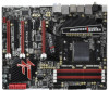
using. www.asrock.com/support/index.asp 1.1 Package Contents Fatal1ty 990FX Professional Series Motherboard (ATX Form Factor: 12.0-in x 9.6-in, 30.5 cm x 24.4 cm) Fatal1ty 990FX Professional Series Quick Installation Guide Fatal1ty 990FX Professional Series Support CD 1 x ASRock SLI_Bridge_2S Card - ASRock Fatal1ty 990FX Professional | User Manual - Page 8
Platform CPU Chipset Memory Expansion Slot Audio LAN - ATX Form Factor: 12.0-in x 9.6-in, 30.5 cm x 24.4 cm - All Solid Capacitor design (100% Japan-made high-quality Conductive Polymer Capacitors) - Support for Socket AM3+ processors - Support for Socket AM3 processors: AMD PhenomTM - ASRock Fatal1ty 990FX Professional | User Manual - Page 9
- 1 x HDMI_SPDIF header - 1 x Power LED header - CPU/Chassis/Power FAN connector - 24 pin ATX power connector - 8 pin 12V power connector - Front panel audio connector - 2 x USB 2.0 headers (support 4 USB 2.0 ports) - 2 x USB 3.0 headers (support 4 USB 3.0 ports) - 1 x Dr. Debug (7-Segment Debug - ASRock Fatal1ty 990FX Professional | User Manual - Page 10
jumperfree - SMBIOS 2.3.1 Support - CPU, VCCM, NB, SB Voltage Multi-adjustment Support CD - Drivers, Utilities, AntiVirus Software (Trial Version), CyberLink MediaEspresso 6.5 Trial, AMD Fusion, AMD Fusion Media Explorer, ASRock Software Suite (CyberLink DVD Suite - OEM and Trial) Unique - ASRock Fatal1ty 990FX Professional | User Manual - Page 11
the upgrade CPU performance with a better price. Please be noted that UCC feature is supported with AM3 CPU only, and in addition, not every AM3 CPU can support this function because some CPU's hidden core may be malfunctioned. 2. This motherboard supports Untied Overclocking Technology. Please - ASRock Fatal1ty 990FX Professional | User Manual - Page 12
40% faster than before. ASRock APP Charger allows you to quickly charge many Apple devices simultaneously and even supports continuous charging when your PC enters into Standby mode (S1), Suspend to RAM (S3), hibernation mode (S4) or power off (S5). With APP Charger driver installed, you can easily - ASRock Fatal1ty 990FX Professional | User Manual - Page 13
Energy Using Product, was a provision regulated by European Union to define the power consumption for the completed system. According to EuP, the total AC power of the completed system shall be under 1.00W in off mode condition. To meet EuP standard, an EuP ready motherboard and an EuP ready power - ASRock Fatal1ty 990FX Professional | User Manual - Page 14
PHY AUDIO CODEC PCIE1 1394a USB 3.0 SATA3 6Gbs PCIE2 AMD 990FX Chipset Super I/O PCIE3 XFast USB CMOS BATTERY PCI1 FATAL1 TY PCIE4 990FX PROFESSIONAL AMD SB950 Chipset SATA3_5_6 SPEAKER1 1 SATA3_3_4 32Mb BIOS HD_AUDIO1 FRONT_1394 1 1 PCI2 RoHS IR1 1 1 PCIE5 COM1 PLED1 1 PANEL - ASRock Fatal1ty 990FX Professional | User Manual - Page 15
3 4 56 7 8 11 9 12 10 13 21 20 19 18 1 PS/2 Mouse Port (Green) 2 Coaxial SPDIF Out Port *3 LAN RJ-45 Port 4 USB 2.0 Ports (USB23) 5 Fatal1ty Mouse Port (USB4) 6 USB 2.0 Port (USB5) *7 LAN RJ-45 Port 8 Side Speaker (Gray) 9 Rear Speaker (Black) 10 Central / Bass (Orange) 11 Line In (Light Blue - ASRock Fatal1ty 990FX Professional | User Manual - Page 16
Primary output" to use Rear Speaker, Central/Bass, and Front Speaker, or select "Realtek HDA Audio 2nd output" to use front panel audio. *** eSATA3 connector supports SATA Gen3 in cable 1M. 16 - ASRock Fatal1ty 990FX Professional | User Manual - Page 17
, peripherals, and/or components. 1. Unplug the power cord from the wall socket before touching any component. 2. To avoid damaging the motherboard components due to static electricity, NEVER place your motherboard directly on the carpet or the like. Also remember to use a grounded wrist strap - ASRock Fatal1ty 990FX Professional | User Manual - Page 18
Corner Small Triangle STEP 2 / STEP 3: STEP 4: Match The CPU Golden Triangle Push Down And Lock To The Socket Corner Small The Socket Lever Triangle 2.2 Installation of CPU Fan and Heatsink After you install the CPU into this motherboard, it is necessary to install a larger heatsink and - ASRock Fatal1ty 990FX Professional | User Manual - Page 19
2.3 Installation of Memory Modules (DIMM) This motherboard provides four 240-pin DDR3 (Double Data Rate 3) DIMM slots, and supports Dual Channel Memory Technology. For dual channel configuration, you always need to install identical (the same brand, speed, size and chip-type) DDR3 DIMM pair in the - ASRock Fatal1ty 990FX Professional | User Manual - Page 20
matches the break on the slot. break notch notch break The DIMM only fits in one correct orientation. It will cause permanent damage to the motherboard and the DIMM if you force the DIMM into the slot at incorrect orientation. Step 3. Firmly insert the DIMM into the slot until the retaining - ASRock Fatal1ty 990FX Professional | User Manual - Page 21
lane width graphics cards, or used to install PCI Express graphics cards to support SLITM and CrossFireXTM function. PCIE5 (PCIE x16 slot; Red) is used for the installation. Step 2. Remove the system unit cover (if your motherboard is already installed in a chassis). Step 3. Remove the bracket facing - ASRock Fatal1ty 990FX Professional | User Manual - Page 22
Guide This motherboard supports NVIDIA® SLITM and Quad SLITM (Scalable Link Interface) technology that allows you to install up to three identical PCI Express x16 graphics cards. Currently, NVIDIA® SLITM technology supports card driver supports NVIDIA® SLITM technology. Download the driver from - ASRock Fatal1ty 990FX Professional | User Manual - Page 23
to the goldfingers on each graphics card. Make sure ASRock SLI_Bridge_2S Card is firmly in place. Step 4. Connect a VGA cable or a DVI cable to the monitor connector or the DVI connector of the graphics card that is inserted to PCIE2 slot. 2.5.2 Driver Installation and Setup Install the graphics card - ASRock Fatal1ty 990FX Professional | User Manual - Page 24
For Windows® VistaTM / VistaTM 64-bit / 7 / 7 64-bit OS: (For SLITM and Quad SLITM mode) A. Click the Start icon on your Windows taskbar. B. From the pop-up menu, select All Programs, and then click NVIDIA Corporation. C. Select NVIDIA Control Panel tab. D. Select Control Panel tab. E. From the pop- - ASRock Fatal1ty 990FX Professional | User Manual - Page 25
Guide This motherboard supports supported with Windows® XP with Service Pack 2 / VistaTM / 7 OS. 3-way CrossFireXTM and Quad CrossFireXTM feature are supported with Windows® VistaTM / 7 OS only. Please check AMD website for AMDTM CrossFireXTM driver updates manuals for detailed installation guide. - ASRock Fatal1ty 990FX Professional | User Manual - Page 26
Bridge Interconnects on the top of Radeon graphics cards. (CrossFire Bridge is provided with the graphics card you purchase, not bundled with this motherboard. Please refer to your graphics card vendor for details.) CrossFire Bridge or Step 3. Connect the DVI monitor cable to the DVI connector - ASRock Fatal1ty 990FX Professional | User Manual - Page 27
Bridge to connect Radeon graphics cards on PCIE4 and PCIE5 slots. (CrossFireTM Bridge is provided with the graphics card you purchase, not bundled with this motherboard. Please refer to your graphics card vendor for details.) 27 - ASRock Fatal1ty 990FX Professional | User Manual - Page 28
CrossFireTM Bridge Step 5. Connect the DVI monitor cable to the DVI connector on the Radeon graphics card on PCIE2 slot. (You may use the DVI to D-Sub adapter to convert the DVI connector to D-Sub interface, and then connect the D-Sub monitor cable to the DVI to D-Sub adapter.) 28 - ASRock Fatal1ty 990FX Professional | User Manual - Page 29
utility to uninstall any previously installed Catalyst drivers prior to installation. Please check AMD website for ATITM driver updates. Step 3. Step 4. Step 5. Install the required drivers to your system. For Windows® XP OS: A. AMDTM recommends Windows® XP Service Pack 2 or higher to be installed - ASRock Fatal1ty 990FX Professional | User Manual - Page 30
technology, please check AMD website for updates and details. 2.7 Surround Display Feature This motherboard supports Surround Display upgrade. With the external add-on PCI Express VGA cards, you can easily enjoy the benefits of Surround Display feature. For the detailed instruction, please refer to - ASRock Fatal1ty 990FX Professional | User Manual - Page 31
short pin2 and pin3 on CLRCMOS1 for 5 seconds. However, please do not clear the CMOS right after you update the BIOS. If you need to clear the CMOS when you just finish updating the BIOS, you must boot up the system first, and then shut it down before you do the clear-CMOS action - ASRock Fatal1ty 990FX Professional | User Manual - Page 32
data cable can be connected to the SATA3 hard disk or the SATA3 connector on this motherboard. Either end of the 3.5mm audio cable can be connected to the portable audio devices on the I/O panel, there are two USB 2.0 headers on this motherboard. Each USB 2.0 header can support two USB 2.0 ports. - ASRock Fatal1ty 990FX Professional | User Manual - Page 33
panel, there are two USB 3.0 headers on this motherboard. Each USB 3.0 header can support two USB 3.0 ports. Infrared Module Header (5-pin supports Jack Sensing, but the panel wire on the chassis must support HDA to function correctly. Please follow the instruction in our manual and chassis manual - ASRock Fatal1ty 990FX Professional | User Manual - Page 34
header as below: A. Connect Mic_IN (MIC) to MIC2_L. B. Connect Audio_R (RIN) to OUT2_R and Audio_L (LIN) to OUT2_L. C. Connect Ground (GND) to Ground (GND). D. MIC_RET and OUT_RET are for HD audio panel only. You don't need to connect them for AC'97 audio panel. E. To activate the front mic. For - ASRock Fatal1ty 990FX Professional | User Manual - Page 35
to the ground pin. Though this motherboard provides 4-Pin CPU fan (Quiet Fan) support, the 3-Pin CPU fan still can work successfully even without the fan speed control function. If you plan to connect the 3-Pin CPU fan to the CPU fan connector on this motherboard, please connect it to Pin 1-3. Pin - ASRock Fatal1ty 990FX Professional | User Manual - Page 36
Pin ATX 12V Power Supply Installation 8 4 IEEE 1394 Header (9-pin FRONT_1394) (see p.14 No. 33) Serial port Header (9-pin COM1) (see p.14 No.30) Besides one default IEEE 1394 port on the I/O panel, there is one IEEE 1394 header (FRONT_1394) on this motherboard. This IEEE 1394 header can support - ASRock Fatal1ty 990FX Professional | User Manual - Page 37
connect the HDMI_SPDIF connector of HDMI VGA card to this header. Front USB 3.0 Panel Installation Guide Step 1 Prepare the bundled Front USB 3.0 Panel, four HDD screws, and six chassis USB 3.0 header (USB3_1_2 or USB3_3_4) on the motherboard. Step 6 The Front USB 3.0 Panel is ready to use. 37 - ASRock Fatal1ty 990FX Professional | User Manual - Page 38
Guide Step 1 Unscrew the two screws from the Front Step 2 Put the USB 3.0 cable and the USB 3.0 Panel. rear USB 3.0 bracket together. Step 3 Screw the two screws into the rear USB 3.0 bracket. Step 4 Put the rear USB 3.0 bracket into the chassis. 2.10 Smart Switches This motherboard - ASRock Fatal1ty 990FX Professional | User Manual - Page 39
to provide code information, which makes troubleshooting even easier. Please see the diagrams below memory CPU initialization is started Pre-memory CPU initialization (CPU module specific) Pre-memory CPU initialization (CPU module specific) Pre-memory CPU initialization (CPU module specific) Pre-memory - ASRock Fatal1ty 990FX Professional | User Manual - Page 40
fied memory initialization error Memory not installed Invalid CPU type or Speed CPU mismatch CPU self test failed or possible CPU cache error CPU micro-code is not found or micro-code update is failed Internal CPU error reset PPI is not available Reserved for future AMI error codes S3 Resume is - ASRock Fatal1ty 990FX Professional | User Manual - Page 41
Services CPU DXE initialization is started CPU DXE initialization (CPU module specific) CPU DXE initialization (CPU module specific) CPU DXE initialization (CPU module specific) CPU DXE initialization (CPU Device Selection (BDS) phase is started Driver connecting is started PCI Bus initialization is - ASRock Fatal1ty 990FX Professional | User Manual - Page 42
below) Ready To Boot event Legacy Boot event Exit Boot Services event Runtime Set Virtual Address MAP Begin Runtime Set Virtual Address future AMI codes OEM BDS initialization codes CPU initialization error North Bridge initialization error South update is failed Reset protocol is not available 42 - ASRock Fatal1ty 990FX Professional | User Manual - Page 43
Hard Disks Installation This motherboard adopts AMD SB950 chipset that supports Serial ATA3 (SATA3) hard disks and RAID (RAID 0, RAID 1, RAID 0+1, JBOD and RAID 5) functions. You may install SATA3 hard disks on this motherboard for internal storage devices. This section will guide you to install the - ASRock Fatal1ty 990FX Professional | User Manual - Page 44
is installed into system properly. The latest SATA3 driver is available on our support website: www.asrock.com 4. Make sure to use the SATA power cable & data cable, which are from our motherboard package. 5. Please follow below instructions step by step to reduce the risk of HDD crash or data - ASRock Fatal1ty 990FX Professional | User Manual - Page 45
data cable to end (White) to the power supply 1x4-pin the motherboard's SATAII / SATA3 cable. connector. SATA power cable 1x4-pin power of attention, before you process the Hot Unplug: Please do follow below instruction sequence to process the Hot Unplug, improper procedure will cause the SATA3 - ASRock Fatal1ty 990FX Professional | User Manual - Page 46
]. (For SATA3_1 to SATA3_6 ports.) Set the option "Marvell SATA3 Operation Mode" to [RAID]. (For eSATA3 ports.) STEP 2: Make a SATA3 Driver Diskette. (Please use USB floppy or floppy disk.) A. Insert the ASRock Support CD into your optical drive to boot your system. B. During POST at the beginning of - ASRock Fatal1ty 990FX Professional | User Manual - Page 47
function, you need to check the RAID installation guide in the Support CD for proper configuration. Please refer to the BIOS RAID installation guide part of the document in the following path in the Support CD: .. \ RAID Installation Guide STEP 3: Make a SATA3 Driver Diskette. (Please use USB floppy - ASRock Fatal1ty 990FX Professional | User Manual - Page 48
64-bit Without RAID Functions If you want to install Windows® XP / XP 64-bit on your SATA3 HDDs without RAID functions, please follow driver. When prompted, insert the SATA3 driver diskette containing the AMD AHCI driver. After reading the floppy disk, the driver will be presented. Select the driver - ASRock Fatal1ty 990FX Professional | User Manual - Page 49
motherboard supports Untied Overclocking Technology, which means during overclocking, FSB enjoys better margin due to fixed PCI / PCIE buses. Before you enable Untied Overclocking function, please enter "Overclock Mode" option of UEFI setup to set the selection from [Auto] to [Manual]. Therefore, CPU - ASRock Fatal1ty 990FX Professional | User Manual - Page 50
steps to set up Teaming function. 1. Install Teaming driver from the following path of motherboard Support CD: 32-bit: .. \Drivers\LAN\Broadcom\Win7-64_Win7_Vista64_Vista_XP64_ XP(v14.8.4.1)\BACS\IA32 64-bit: .. \Drivers\LAN\Broadcom\Win7-64_Win7_Vista64_Vista_XP64_ XP(v14.8.4.1)\BACS\x64 (This - ASRock Fatal1ty 990FX Professional | User Manual - Page 51
the team. The LSO, CO, and RSS properties are enabled for a team only when all of the members support and are configured for the feature. * Adding a network adapter to a team where its driver is disabled may negatively affect the offloading capabilities of the team. This may have an impact on the - ASRock Fatal1ty 990FX Professional | User Manual - Page 52
* When team configuration has been correctly performed, a virtual team adapter driver is created for each configured team. * If you disable a virtual hub is supported for testing, it is recommended to connect team members to a switch. * Not all network adapters made by others are supported or fully - ASRock Fatal1ty 990FX Professional | User Manual - Page 53
14. Configure the team IP address. a. From Control Panel, double-click Network Connections. b. Right-click the name of the team to be configured, and then click Properties. c. On the General tab, click Internet Protocol (TCP/IP), - ASRock Fatal1ty 990FX Professional | User Manual - Page 54
Memory on the motherboard stores the UEFI SETUP UTILITY. You may run the UEFI SETUP UTILITY when you start up the computer. Please press or during the Power-On-Self-Test (POST) to enter the UEFI SETUP UTILITY, otherwise, POST will continue with its test updated, overclocking - ASRock Fatal1ty 990FX Professional | User Manual - Page 55
3.1.2 Navigation Keys Please check the following table for the function description of each navigation key. Navigation Key(s) / / + / Function Description Moves cursor left or right to select Screens Moves cursor up or down to select items To change option for the - ASRock Fatal1ty 990FX Professional | User Manual - Page 56
Mode Use this to select Overclock Mode. Configuration options: [Auto] and [Manual]. The default value is [Auto]. Spread Spectrum This item should always be [Auto] for better system stability. ASRock UCC ASRock UCC (Unlock CPU Core) feature simplifies AMD CPU activation. As long as a simple switch - ASRock Fatal1ty 990FX Professional | User Manual - Page 57
is set to [Auto] by default. If it is set to [Manual], you may adjust the value of Processor Frequency and Processor Voltage. However, figuration DRAM Frequency If [Auto] is selected, the motherboard will detect the memory module(s) inserted and assigns appropriate frequency automatically. DRAM Timing - ASRock Fatal1ty 990FX Professional | User Manual - Page 58
Channel Interleaving It allows you to enable Channel Memory Interleaving. Configuration options: [Disabled], [Auto]. The default value is [Auto]. CAS# Latency (tCL) Use this item to change CAS# Latency (tCL) Auto/Manual setting. The default is [Auto]. RAS# to CAS# Delay (tRCD) Use this item to change - ASRock Fatal1ty 990FX Professional | User Manual - Page 59
-line calibration Use this to select CPU Load-line calibration. The default value is [Auto]. DRAM Auto]. HT Voltage Use this to select HT Voltage. The default value is [Auto]. CPU VDDA Voltage Use this to select CPU VDDA Voltage. The default value is [Auto]. PCIE VDDA Voltage Use this to select PCIE - ASRock Fatal1ty 990FX Professional | User Manual - Page 60
you may set the configurations for the following items: CPU Configuration, Nouth Bridge Configuration, South Bridge Configuration, file to your USB flash drive, floppy disk or hard drive, then you can update your UEFI only in a few clicks without preparing an additional floppy diskette or other complicated - ASRock Fatal1ty 990FX Professional | User Manual - Page 61
). The C1 state is supported through the native processor instructions HLT and MWAIT and requires no hardware support from the chipset. In the C1 power state, the processor maintains the context of the system caches. CPU Thermal Throttle Use this item to enable CPU internal thermal control mechanism - ASRock Fatal1ty 990FX Professional | User Manual - Page 62
3.4.2 North Bridge Configuration Primary Graphics Adapter This item will switch the PCI Bus scanning order while searching for video card. It allows you to select the type of Primary VGA in case of multiple video controllers. The default value of this feature is [PCI Express]. Configuration options: - ASRock Fatal1ty 990FX Professional | User Manual - Page 63
3.4.3 South Bridge Configuration Onboard HD Audio Select [Auto], [Enabled] or [Disabled] for the onboard HD Audio feature. If you select [Auto], the onboard HD Audio will be disabled when PCI Sound Card is plugged. Front Panel Select [Auto] or [Disabled] for the onboard HD Audio Front Panel. On/Off - ASRock Fatal1ty 990FX Professional | User Manual - Page 64
SATA Mode. The default value of this option is [IDE Mode]. Configuration options: [AHCI Mode], [RAID Mode] and [IDE Mode]. If you set this item to RAID mode, it is suggested to install SATA ODD driver on SATA3_5 or SATA3_6 port. SATA IDE Combined Mode This item is for SATA3_5 and SATA3_6 - ASRock Fatal1ty 990FX Professional | User Manual - Page 65
We recommend to use SATA3_1 to SATA3_6 ports for your bootable device. This will minimum your boot time and get the best performance. But if you still want to boot from Marvell SATA3 controller, please set this item to [Yes]. Hard Disk S.M.A.R.T. Use this item to enable or disable the S.M.A.R.T. ( - ASRock Fatal1ty 990FX Professional | User Manual - Page 66
3.4.5 Super IO Configuration Serial Port Use this item to enable or disable the onboard serial port. Serial Port Address Use this item to set the address for the onboard serial port. Configuration options: [3F8h / IRQ4] and [3E8h / IRQ4]. Infrared Port Use this item to enable or disable the onboard - ASRock Fatal1ty 990FX Professional | User Manual - Page 67
to RAM Use this item to select whether to auto-detect or disable the Suspend-toRAM feature. Select [Auto] will enable this feature if the OS supports it when the power recovers. If [Power On] is selected, the AC/power resumes and the system starts to boot up when the power recovers. PS/2 Keyboard - ASRock Fatal1ty 990FX Professional | User Manual - Page 68
item to enable or disable ACPI HPET Table. The default value is [Enabled]. Please set this option to [Enabled] if you plan to use this motherboard to submit Windows® VistaTM certification. 68 - ASRock Fatal1ty 990FX Professional | User Manual - Page 69
[Auto] and [UEFI Setup Only]. The default value is [Enabled]. Please refer to below descriptions for the details of these four options: [Enabled] - Enables support for legacy USB. [Disabled] - USB devices are not allowed to use under legacy OS and UEFI setup when [Disabled] is selected. If you have - ASRock Fatal1ty 990FX Professional | User Manual - Page 70
of the hardware on your system, including the parameters of the CPU temperature, motherboard temperature, CPU fan speed, chassis fan speed, and the critical voltage. CPU Fan 1 & 2 Setting This allows you to set the CPU fan 1 & 2 speed. Confi guration options: [Full On] and [Automatic Mode]. The - ASRock Fatal1ty 990FX Professional | User Manual - Page 71
3.6 Boot Screen In this section, it will display the available devices on your system for you to configure the boot settings and the boot priority. Boot Option Priorities Boot Option #1 Set the first priority of the system boot device. Hard Drive BBS Priorities Set the order of the legacy devices in - ASRock Fatal1ty 990FX Professional | User Manual - Page 72
3.7 Security Screen In this section, you may set or change the supervisor/user password for the system. For the user password, you may also clear it. 72 - ASRock Fatal1ty 990FX Professional | User Manual - Page 73
3.8 Exit Screen Save Changes and Exit When you select this option, it will pop-out the following message, "Save configuration changes and exit setup?" Select [Yes] to save the changes and exit the UEFI SETUP UTILITY. Discard Changes and Exit When you select this option, it will pop-out the following - ASRock Fatal1ty 990FX Professional | User Manual - Page 74
install the necessary drivers to activate the devices. 4.2.3 Utilities Menu The Utilities Menu shows the applications software that the motherboard supports. Click on a specific item then follow the installation wizard to install it. 4.2.4 Contact Information If you need to contact ASRock or want to - ASRock Fatal1ty 990FX Professional | User Manual - Page 75
Installing OS on a HDD Larger Than 2TB This motherboard is adopting UEFI BIOS that allows Windows® OS to be installed on a large size HDD (>2TB). Please follow below procedure to install the operating system. 1. Please make sure to
-
 1
1 -
 2
2 -
 3
3 -
 4
4 -
 5
5 -
 6
6 -
 7
7 -
8
-
9
-
10
-
11
-
12
-
13
-
14
-
15
-
16
-
17
-
18
-
19
-
20
-
21
-
22
-
23
-
24
-
25
-
26
-
27
-
28
-
29
-
30
-
31
-
32
-
33
-
34
-
35
-
36
-
37
-
38
-
39
-
40
-
41
-
42
-
43
-
44
-
45
-
46
-
47
-
48
-
49
-
50
-
51
-
52
-
53
-
54
-
55
-
56
-
57
-
58
-
59
-
60
-
61
-
62
-
63
-
64
-
65
-
66
-
67
-
68
-
69
-
70
-
71
-
72
-
73
-
74
-
75
 |
 |

1
Fatal1ty 990FX Professional Series
User Manual
Version 1.0
Published June 2011
Copyright©2011 ASRock INC. All rights reserved.