ASRock Fatal1ty 990FX Professional Quick Installation Guide
ASRock Fatal1ty 990FX Professional Manual
 |
View all ASRock Fatal1ty 990FX Professional manuals
Add to My Manuals
Save this manual to your list of manuals |
ASRock Fatal1ty 990FX Professional manual content summary:
- ASRock Fatal1ty 990FX Professional | Quick Installation Guide - Page 1
World's 1st Doom3 Champion by defeating Daler in a series of very challenging matches and earning $25,000 for the victory. Since then Fatal1ty has traveled the globe to compete against the best has become the figurehead for eSports worldwide". 1 Fatal1ty 990FX Professional Series Motherboard English - ASRock Fatal1ty 990FX Professional | Quick Installation Guide - Page 2
The Fatal1ty name, Fatal1ty logos and the Fatal1ty likeness are registered trademarks of Fatal1ty, Inc., and are used under license. © 2011 Fatal1ty, Inc. All rights reserved. All other trademarks are the property of their respective owners. 2 Fatal1ty 990FX Professional Series Motherboard English - ASRock Fatal1ty 990FX Professional | Quick Installation Guide - Page 3
the related regulations in advance. "Perchlorate Material-special handling may apply, see www.dtsc.ca.gov/hazardouswaste/perchlorate" ASRock Website: http://www.asrock.com Published June 2011 Copyright©2011 ASRock INC. All rights reserved. 3 Fatal1ty 990FX Professional Series Motherboard English - ASRock Fatal1ty 990FX Professional | Quick Installation Guide - Page 4
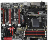
2 ATX 12V Power Connector (ATX12V1) 22 Power Switch (PWRBTN) 3 AM3+ CPU Socket 23 Dr. Debug (LED) 4 CPU Fan Connector (CPU_FAN1) 24 Chassis Fan Connector (CHA_FAN3) 5 CPU Fan (CHA_FAN1) 41 PCI Express 2.0 x1 Slot (PCIE1; Black) English 4 Fatal1ty 990FX Professional Series Motherboard - ASRock Fatal1ty 990FX Professional | Quick Installation Guide - Page 5
speaker you use. TABLE for Audio Output Connection Audio Output Channels Front Speaker Rear Speaker Central / Bass Side Speaker (No. 12) (No. 9) (No. 10) (No. 8) 2 V -- -- -- 4 V V -- -- 6 V V V -- 8 V V V V 5 Fatal1ty 990FX Professional Series Motherboard English - ASRock Fatal1ty 990FX Professional | Quick Installation Guide - Page 6
Primary output" to use Rear Speaker, Central/Bass, and Front Speaker, or select "Realtek HDA Audio 2nd output" to use front panel audio. *** eSATA3 connector supports SATA Gen3 in cable 1M. English 6 Fatal1ty 990FX Professional Series Motherboard - ASRock Fatal1ty 990FX Professional | Quick Installation Guide - Page 7
using. www.asrock.com/support/index.asp 1.1 Package Contents Fatal1ty 990FX Professional Series Motherboard (ATX Form Factor: 12.0-in x 9.6-in, 30.5 cm x 24.4 cm) Fatal1ty 990FX Professional Series Quick Installation Guide Fatal1ty 990FX Professional Series Support CD 1 x ASRock SLI_Bridge_2S Card - ASRock Fatal1ty 990FX Professional | Quick Installation Guide - Page 8
- Premium Blu-ray audio support - Supports THX TruStudioTM - PCIE x1 Gigabit LAN 10/100/1000 Mb/s - Broadcom BCM57781 - Supports Wake-On-LAN - Supports Energy Efficient Ethernet 802.3az - Supports Dual LAN with Teaming function - Supports PXE 8 Fatal1ty 990FX Professional Series Motherboard English - ASRock Fatal1ty 990FX Professional | Quick Installation Guide - Page 9
ports) - 1 x Dr. Debug (7-Segment Debug LED) - 1 x Clear CMOS Switch with LED - 1 x Power Switch with LED - 1 x Reset Switch with LED - 32Mb AMI UEFI Legal BIOS with GUI support - Supports "Plug and Play" - ACPI 1.1 Compliance Wake Up Events English 9 Fatal1ty 990FX Professional Series Motherboard - ASRock Fatal1ty 990FX Professional | Quick Installation Guide - Page 10
tools. Overclocking may affect your system stability, or even cause damage to the components and devices of your system. It should be done at your own risk and expense. We are not responsible for possible damage caused by overclocking. English 10 Fatal1ty 990FX Professional Series Motherboard - ASRock Fatal1ty 990FX Professional | Quick Installation Guide - Page 11
to add a professional level mouse configuration. In IES (Intelligent Energy Saver) mode, the voltage regulator can reduce the number of output phases to improve efficiency when the CPU cores are idle without sacrificing computing performance. 11 Fatal1ty 990FX Professional Series Motherboard English - ASRock Fatal1ty 990FX Professional | Quick Installation Guide - Page 12
check if the CPU fan on the motherboard functions properly and unplug the power cord, then plug it back again. To improve heat dissipation, remember to spray thermal grease between the CPU and the heatsink when you install the PC system. 12 Fatal1ty 990FX Professional Series Motherboard English - ASRock Fatal1ty 990FX Professional | Quick Installation Guide - Page 13
regulated by European Union to define the power consumption for the completed system. According to EuP, the total AC power of the completed system shall be under 1.00W in off mode condition. To meet EuP standard, an EuP ready motherboard . 13 Fatal1ty 990FX Professional Series Motherboard English - ASRock Fatal1ty 990FX Professional | Quick Installation Guide - Page 14
wall socket before touching any component. 2. To avoid damaging the motherboard components due to static electricity, NEVER place your motherboard motherboard to the chassis, please do not over-tighten the screws! Doing so may damage the motherboard. 14 Fatal1ty 990FX Professional Series Motherboard - ASRock Fatal1ty 990FX Professional | Quick Installation Guide - Page 15
with each other. Then connect the CPU fan to the CPU FAN connector (CPU_FAN1, see Page 4, No. 4 or CPU_FAN2, see Page 4, No. 5). For proper installation, please kindly refer to the instruction manuals of the CPU fan and the heatsink. English 15 Fatal1ty 990FX Professional Series Motherboard - ASRock Fatal1ty 990FX Professional | Quick Installation Guide - Page 16
to install a DDR or DDR2 memory module into DDR3 slot; otherwise, this motherboard and DIMM may be damaged. 6. If you adopt DDR3 2100 memory modules on this motherboard, it is recommended to install them on DDR3_A2 and DDR3_B2 slots. 16 Fatal1ty 990FX Professional Series Motherboard English - ASRock Fatal1ty 990FX Professional | Quick Installation Guide - Page 17
to the motherboard and the DIMM if you force the DIMM into the slot at incorrect orientation. Step 3. Firmly insert the DIMM into the slot until the retaining clips at both ends fully snap back in place and the DIMM is properly seated. 17 Fatal1ty 990FX Professional Series Motherboard English - ASRock Fatal1ty 990FX Professional | Quick Installation Guide - Page 18
for PCI Express x16 lane width graphics cards, or used to install PCI Express graphics cards to support SLITM and CrossFireXTM function. PCIE5 (PCIE x16 slot; Red) is used for PCI Express x4 lane screws. Step 6. Replace the system cover. 18 Fatal1ty 990FX Professional Series Motherboard English - ASRock Fatal1ty 990FX Professional | Quick Installation Guide - Page 19
cards that are NVIDIA® certified. 2. Make sure that your graphics card driver supports NVIDIA® SLITM technology. Download the driver from NVIDIA® website (www.nvidia.com). 3. Make sure that your power source to the PCI Express graphics cards. 19 Fatal1ty 990FX Professional Series Motherboard English - ASRock Fatal1ty 990FX Professional | Quick Installation Guide - Page 20
ASRock SLI_Bridge_2S Card is firmly in place. Step4. Connect a VGA cable or a DVI cable to the monitor connector or the DVI connector of the graphics card that is inserted to PCIE2 slot. 2.5.2 Driver freely enjoy the benefit of SLITM feature. 20 Fatal1ty 990FX Professional Series Motherboard English - ASRock Fatal1ty 990FX Professional | Quick Installation Guide - Page 21
a registered trademark of NVIDIA® Technologies Inc., and is used only for identification or explanation and to the owners' benefit, without intent to infringe. 21 Fatal1ty 990FX Professional Series Motherboard English - ASRock Fatal1ty 990FX Professional | Quick Installation Guide - Page 22
please refer to AMDTM graphics card manuals for detailed installation guide. Step 1. Insert one Radeon graphics card into PCIE2 slot and the other Radeon graphics card to PCIE4 slot. Make sure that the cards are properly seated on the slots. 22 Fatal1ty 990FX Professional Series Motherboard English - ASRock Fatal1ty 990FX Professional | Quick Installation Guide - Page 23
(CrossFire Bridge is provided with the graphics card you purchase, not bundled with this motherboard. Please refer to your graphics card vendor for details.) CrossFire Bridge or Step 3. monitor cable to the DVI to D-Sub adapter.) English 23 Fatal1ty 990FX Professional Series Motherboard - ASRock Fatal1ty 990FX Professional | Quick Installation Guide - Page 24
Bridge to connect Radeon graphics cards on PCIE4 and PCIE5 slots. (CrossFireTM Bridge is provided with the graphics card you purchase, not bundled with this motherboard. Please refer to your graphics card vendor for details.) 24 Fatal1ty 990FX Professional Series Motherboard - ASRock Fatal1ty 990FX Professional | Quick Installation Guide - Page 25
D-Sub adapter to convert the DVI connector to D-Sub interface, and then connect the D-Sub monitor cable to the DVI to D-Sub adapter.) English 25 Fatal1ty 990FX Professional Series Motherboard - ASRock Fatal1ty 990FX Professional | Quick Installation Guide - Page 26
drivers prior to installation. Please check AMD website for ATITM driver updates. Step 3. Step 4. Step 5. Install the required drivers to your system. For Windows® XP OS: A. AMDTM recommends Windows® XP Service Radeon graphics cards). English 26 Fatal1ty 990FX Professional Series Motherboard - ASRock Fatal1ty 990FX Professional | Quick Installation Guide - Page 27
the external add-on PCI Express VGA cards, you can easily enjoy the benefits of Surround Display feature. For the detailed instruction, please refer to the document at the following path in the Support CD: ..\ Surround Display Information 27 Fatal1ty 990FX Professional Series Motherboard English - ASRock Fatal1ty 990FX Professional | Quick Installation Guide - Page 28
you update the BIOS. If you need to clear the CMOS when you just finish updating the BIOS, you GUID and MAC address will be cleared only if the CMOS battery is removed. The Clear CMOS Switch has the same function as the Clear CMOS jumper. English 28 Fatal1ty 990FX Professional Series Motherboard - ASRock Fatal1ty 990FX Professional | Quick Installation Guide - Page 29
can be connected to the SATA3 hard disk or the SATA3 connector on this motherboard. Either end of the 3.5mm audio cable can be connected to the headers on 1 GND P+6 P-6 USB PWR this motherboard. Each USB 2.0 header can support two USB 2.0 ports. 29 Fatal1ty 990FX Professional Series Motherboard - ASRock Fatal1ty 990FX Professional | Quick Installation Guide - Page 30
Jack Sensing, but the panel wire on the chassis must support HDA to function correctly. Please follow the instruction in our manual and chassis manual to install your system. 2. If you use AC'97 audio panel, please install it to the front panel audio 30 Fatal1ty 990FX Professional Series Motherboard - ASRock Fatal1ty 990FX Professional | Quick Installation Guide - Page 31
etc. When connecting your chassis front panel module to this header, make sure the wire assignments and the pin assign-ments are matched correctly. 31 Fatal1ty 990FX Professional Series Motherboard English - ASRock Fatal1ty 990FX Professional | Quick Installation Guide - Page 32
speed control function. If you plan to connect the 3-Pin CPU fan to the CPU fan connector on this motherboard, please connect it to Pin 1-3. Pin 1-3 Connected 3-Pin Fan Installation (3-pin CPU_FAN2) (see p.4 No. 5) +12V GND CPU_FAN_SPEED English 32 Fatal1ty 990FX Professional Series Motherboard - ASRock Fatal1ty 990FX Professional | Quick Installation Guide - Page 33
) (see p.4 No.30) Besides one default IEEE 1394 port on the I/O panel, there is one IEEE 1394 header (FRONT_1394) on this motherboard. This IEEE 1394 header can support one IEEE 1394 port. This COM1 header supports a serial port module. English 33 Fatal1ty 990FX Professional Series Motherboard - ASRock Fatal1ty 990FX Professional | Quick Installation Guide - Page 34
connector of HDMI VGA card to this header. Front USB 3.0 Panel Installation Guide Step 1 Prepare the bundled Front USB 3.0 Panel, four HDD screws, and or USB3_3_4) on the motherboard. Step 6 The Front USB 3.0 Panel is ready to use. English 34 Fatal1ty 990FX Professional Series Motherboard - ASRock Fatal1ty 990FX Professional | Quick Installation Guide - Page 35
reset the system. Clear CMOS Switch (CLRCBTN) (see p.5 No. 20) Clear CMOS Switch is a smart switch, allowing users to quickly clear the CMOS values 35 Fatal1ty 990FX Professional Series Motherboard English - ASRock Fatal1ty 990FX Professional | Quick Installation Guide - Page 36
. Cache initialization CPU post-memory initialization. Application Processor(s) (AP) initialization CPU post-memory initialization. Boot Strap Processor (BSP) selection CPU post-memory initialization. System Management Mode (SMM) initialization Fatal1ty 990FX Professional Series Motherboard English - ASRock Fatal1ty 990FX Professional | Quick Installation Guide - Page 37
PPI is not available Recovery capsule is not found Invalid recovery capsule Reserved for future AMI error codes DXE Core is started NVRAM initialization 37 Fatal1ty 990FX Professional Series Motherboard English - ASRock Fatal1ty 990FX Professional | Quick Installation Guide - Page 38
Services CPU DXE initialization is started CPU DXE initialization (CPU module specific) CPU DXE initialization (CPU module specific) CPU DXE initialization (CPU module specific) CPU DXE initialization (CPU ) phase is started Driver connecting is started PCI Fatal1ty 990FX Professional Series Motherboard - ASRock Fatal1ty 990FX Professional | Quick Installation Guide - Page 39
To Boot event Legacy Boot event Exit Boot Services event Runtime Set Virtual Address MAP Begin Runtime Set codes OEM BDS initialization codes CPU initialization error North Bridge update is failed Reset protocol is not available English 39 Fatal1ty 990FX Professional Series Motherboard - ASRock Fatal1ty 990FX Professional | Quick Installation Guide - Page 40
XP / XP 64bit on your SATA3 HDDs with RAID functions, please refer to the document at the following path in the Support CD for detailed procedures: ..\ RAID Installation Guide 2.14 Installing Windows® 7 / 7 64-bit 64-bit OS on your system. 40 Fatal1ty 990FX Professional Series Motherboard English - ASRock Fatal1ty 990FX Professional | Quick Installation Guide - Page 41
overclocking, but PCI / PCIE buses are in the fixed mode so that FSB can operate under a more stable overclocking environment. Please refer to the warning on page 10 for the possible overclocking risk before you apply Untied Overclocking Technology. 41 Fatal1ty 990FX Professional Series Motherboard - ASRock Fatal1ty 990FX Professional | Quick Installation Guide - Page 42
network prevents network downtime by transferring the workload from a failed port to a working port. The speed of transmission is subject to the actual network Teaming, please install the LAN driver provided by our support CD link.) 2. From the Fatal1ty 990FX Professional Series Motherboard English - ASRock Fatal1ty 990FX Professional | Quick Installation Guide - Page 43
its driver is disabled may negatively affect the offloading capabilities of the team. This may have an impact on the team's performance. Therefore, it is recommended that only driver-enabled network adapters be added as members to a team. 43 Fatal1ty 990FX Professional Series Motherboard English - ASRock Fatal1ty 990FX Professional | Quick Installation Guide - Page 44
correctly performed, a virtual team adapter driver is created for each configured team supported for testing, it is recommended to connect team members to a switch. * Not all network adapters made by others are supported or fully certified for teaming. 44 Fatal1ty 990FX Professional Series Motherboard - ASRock Fatal1ty 990FX Professional | Quick Installation Guide - Page 45
14. Configure the team IP address. a. From Control Panel, double-click Network Connections. b. Right-click the name of the team to be configured, and then click Properties TCP/IP configuration for the team, and then click OK when finished. 45 Fatal1ty 990FX Professional Series Motherboard English - ASRock Fatal1ty 990FX Professional | Quick Installation Guide - Page 46
your computer. If the Main Menu does not appear automatically, locate and double-click on the file "ASSETUP.EXE" from the BIN folder in the Support CD to display the menus. 46 Fatal1ty 990FX Professional Series Motherboard English - ASRock Fatal1ty 990FX Professional | Quick Installation Guide - Page 47
unsere Webseite: www.asrock.com/support/index.asp 1.1 Kartoninhalt Fatal1ty 990FX Professional Series Motherboard (ATX-Formfaktor: 30.5 cm x 24.4 cm; 12.0 Zoll x 9.6 Zoll) Fatal1ty 990FX Professional Series Schnellinstallationsanleitung Fatal1ty 990FX Professional Series Support-CD Sechs Serial ATA - ASRock Fatal1ty 990FX Professional | Quick Installation Guide - Page 48
Socket AM3+-Prozessoren - Unterstützung von Socket AM3-Prozessoren: AMD Phenom TM II X6 / X4 / X3 / X2 (außer 920 / 940) / Athlon X4 / X3 / X2 / Sempron-Prozessor - Acht-Kern-CPU-bereit - Unterstützt UCC (Unlock CPU Mb/s - Broadcom BCM57781 48 Fatal1ty 990FX Professional Series Motherboard Deutsch - ASRock Fatal1ty 990FX Professional | Quick Installation Guide - Page 49
24-pin ATX-Netz-Header - 8-pin anschluss für 12V-ATX-Netzteil - Anschluss für Audio auf der Gehäusevorderseite - 2 x USB 2.0-Anschlüsse (Unterstützung 4 zusätzlicher USB 2.0-Anschlüsse) - 2 x USB 3.0-Anschlüsse (Unterstützung 4 zusätzlicher Deutsch 49 Fatal1ty 990FX Professional Series Motherboard - ASRock Fatal1ty 990FX Professional | Quick Installation Guide - Page 50
CPU, VCCM, NB, SB Stromspannung Multianpassung Support-CD - Treiber, Dienstprogramme, Antivirussoftware (Probeversion), CyberLink MediaEspresso 6.5-Testversion, AMD Fusion, AMD Fusion Media Explorer, ASRock -Richtlinie (ErP/EuP) erforderlich) 50 Fatal1ty 990FX Professional Series Motherboard - ASRock Fatal1ty 990FX Professional | Quick Installation Guide - Page 51
, da unter Windows® 7 / Vista™ / XP etwas Speicher zur Nutzung durch das System reserviert wird. Unter Windows® OS mit 64-Bit-CPU besteht diese Einschränkung nicht. 6. Der Mikrofoneingang dieses Motherboards unterstützt Stereo- und Mono- 51 Fatal1ty 990FX Professional Series Motherboard Deutsch - ASRock Fatal1ty 990FX Professional | Quick Installation Guide - Page 52
CPU- S1), Suspend to RAM-Modus (S3) ASRock-Webseite: http://www.asrock.com/Feature/AppCharger/index. asp 10. ASRock SmartView, eine neue Internetbrowserfunktion, ist eine intelligente IE-Startseite, die meist besuchte Internetseiten, Ihren Browserver- 52 Fatal1ty 990FX Professional Series Motherboard - ASRock Fatal1ty 990FX Professional | Quick Installation Guide - Page 53
. Durch die ASRock ein/aus-Wiedergabetechnologie Overclocking nicht empfohlen. Frequenzen, die von den empfohlenen CPUBusfrequenzen abweichen, können Instabilität des Systems verursachen oder die CPU beschädigen. 14. Wird eine Überhitzung der CPU Fatal1ty 990FX Professional Series Motherboard Deutsch - ASRock Fatal1ty 990FX Professional | Quick Installation Guide - Page 54
, oder zurück in die Tüte, mit der die Komponente geliefert wurde. 5. Wenn Sie das Motherboard mit den Schrauben an dem Computergehäuse befestigen, überziehen Sie bitte die Schrauben nicht! Das Motherboard kann sonst beschädigt werden. Deutsch 54 Fatal1ty 990FX Professional Series Motherboard - ASRock Fatal1ty 990FX Professional | Quick Installation Guide - Page 55
. Verbinden Sie dann den CPU-Lüfter mit dem CPU-LÜFTER-Anschluss (CPU_FAN1, siehe Seite 4, Nr. 4 oder CPU_FAN2, siehe Seite 4, Nr. 5). Beziehen Sie sich für eine richtige Installation auf die Handbücher des CPU-Lüfters und des Kühlkörpers. Deutsch 55 Fatal1ty 990FX Professional Series Motherboard - ASRock Fatal1ty 990FX Professional | Quick Installation Guide - Page 56
2.3 Installation der Speichermodule (DIMM) Die Motherboards Fatal1ty 990FX Professional Series bieten vier 240-pol. DDR3 (Double Data Rate 3) DIMM-Steckplätze und unterstützen die Dual-KanalSpeichertechnologie. Für die Dual-Kanalkonfiguration dürfen Sie nur identische ( - ASRock Fatal1ty 990FX Professional | Quick Installation Guide - Page 57
, führt dies zu dauerhaften Schäden am Mainboard und am DIMM-Modul. Schritt 3: Drücken Sie die DIMM-Module fest in die Steckplätze, so dass die Halteklammern an beiden Enden des Moduls einschnappen und das DIMM-Modul fest an Ort und Stelle sitzt. 57 Fatal1ty 990FX Professional Series Motherboard - ASRock Fatal1ty 990FX Professional | Quick Installation Guide - Page 58
2.4 Erweiterungssteckplätze: (PCI- und PCI Express-Slots): Es stehen 2 PCI- und 5 PCI Express-Slot auf dem Fatal1ty 990FX Professional Series Motherboard zur Verfügung. PCI-Slots: PCI-Slots werden zur Installation von Erweiterungskarten mit dem 32bit PCI-Interface genutzt. PCI Express-Slots: PCIE1 / - ASRock Fatal1ty 990FX Professional | Quick Installation Guide - Page 59
die CrossFireXTM-Funktion von den Betriebssystemen Windows® XP mit Service Pack 2 / VistaTM / 7 unterstützt. Die AMD-Website nach, ob es AMDTM CrossFireXTM-Treiber-Updates gibt. Beachten Sie den detailliert erklärten Installationsablauf auf Seite 22. 59 Fatal1ty 990FX Professional Series Motherboard - ASRock Fatal1ty 990FX Professional | Quick Installation Guide - Page 60
und die verschiedenen BIOS-Parameter. Um BIOS löschen müssen, müssen Sie zuerst das System starten und dann wieder ausschalten, bevor Sie den CMOS-Inhalt löschen. Der CMOS löschen-Schalter hat dieselbe Funktion wie der CMOS löschen-Jumper. Deutsch 60 Fatal1ty 990FX Professional Series Motherboard - ASRock Fatal1ty 990FX Professional | Quick Installation Guide - Page 61
Sie Jumperkappen auf Header und Anschlüsse setzen, wird das Motherboard unreparierbar beschädigt! Serial ATA- (SATA-) Stromversorgungskabel (Option) zwei USB 2.0- GND P+6 P-6 Anschlussleisten am USB PWR 61 Fatal1ty 990FX Professional Series Motherboard SATA3_1_2 SATA3_3_4 SATA3_5_6 Deutsch - ASRock Fatal1ty 990FX Professional | Quick Installation Guide - Page 62
zwei Standard-USB 3.0-Ports am E/A-Panel befinden sich zwei USB 3.0Anschlussleisten an diesem Motherboard. Pro USB 3.0Anschlussleiste werden zwei USB 3.0-Ports unterstützt. Deutsch Infrarot-Modul-Header (5- und Kontrolle über Audio-Geräte. 62 Fatal1ty 990FX Professional Series Motherboard - ASRock Fatal1ty 990FX Professional | Quick Installation Guide - Page 63
Ruhezustand S1 befindet. Die LED schaltet sich aus, wenn sich das System in den Modi S3/S4 befindet oder ausgeschaltet ist (S5). 63 Fatal1ty 990FX Professional Series Motherboard - ASRock Fatal1ty 990FX Professional | Quick Installation Guide - Page 64
Lüfterkabel mit den Lüfteranschlüssen, wobei der schwarze Draht an den Schutzleiterstift angeschlossenwird. CHA_ FAN1/2/3-Lüftergeschwindigkeit kann über UEFI oder AXTU gesteuert werden. Deutsch 64 Fatal1ty 990FX Professional Series Motherboard - ASRock Fatal1ty 990FX Professional | Quick Installation Guide - Page 65
4-Pin ATX 12V Energieversorgung adoptieren. Um die 4-Pin ATX Energieversorgung zu verwenden, stecken Sie bitte Ihre Energieversorgung zusammen mit dem Pin 1 und Pin 5 ein. 5 1 Installation der 4-Pin ATX 12V Energieversorgung 8 4 65 Fatal1ty 990FX Professional Series Motherboard Deutsch - ASRock Fatal1ty 990FX Professional | Quick Installation Guide - Page 66
wie Fernsehgeräten, Projektoren, LCD-Geräten an das System. Bitte verbinden Sie den HDMI_SPDIF-Anschluss der HDMI-VGA-Karte mit diesem Anschluss. Deutsch 66 Fatal1ty 990FX Professional Series Motherboard - ASRock Fatal1ty 990FX Professional | Quick Installation Guide - Page 67
das Kabel der USB 3.0-Frontblende am USB 3.0-Header (USB3_1_2 oder USB3_3_4) am Motherboard an. Schritt 6 Die USB 3.0-Frontblende ist nun einsatzbereit. Installationsanleitung zum USB 3.0- USB 3.0-Blech an der Rückwand des Gehäuses ein. Deutsch 67 Fatal1ty 990FX Professional Series Motherboard - ASRock Fatal1ty 990FX Professional | Quick Installation Guide - Page 68
2.9 Schnellschalter Dieses Motherboard besitzt drei Schnellschalter: Netzschalter, Rücksetzschalter (Reset) und CMOS löschen-Schalter, mit denen Benutzer das ist ein Schnellschalter, mit dem Benutzer die CMOS-Werte schnell löschen können. Deutsch 68 Fatal1ty 990FX Professional Series Motherboard - ASRock Fatal1ty 990FX Professional | Quick Installation Guide - Page 69
Pfad auf der Unterstützungs-CD finden: ..\ RAID Installation Guide 2.13 Windows® 7 / 7 64-Bit / VistaTM / VistaTM 64-Bit / XP / XP 64-Bit ohne RAID-Funktionalität installieren Wenn Sie Windows® 7 / 7 Windows® XP / XP 64-Bit in Ihrem System. 69 Fatal1ty 990FX Professional Series Motherboard Deutsch - ASRock Fatal1ty 990FX Professional | Quick Installation Guide - Page 70
-Bit / VistaTM / VistaTM 64-Bit ohne RAID-Funktionen Wenn Sie Windows® 7 / 7 64-Bit / VistaTM / VistaTM 64-Bit ohne RAID-Funktionalität auf Ihren SATA3-Festplatten installieren, gehen 7 / 7 64-Bit / VistaTM / VistaTM 64-Bit in Ihrem System. 70 Fatal1ty 990FX Professional Series Motherboard Deutsch - ASRock Fatal1ty 990FX Professional | Quick Installation Guide - Page 71
der Support-CD, um die Menüs aufzurufen. Das Setup-Programm soll es Ihnen so leicht wie möglich machen. Es ist menügesteuert, d.h. Sie können in den verschiedenen Untermenüs Ihre Auswahl treffen und die Programme werden dann automatisch installiert. 71 Fatal1ty 990FX Professional Series Motherboard - ASRock Fatal1ty 990FX Professional | Quick Installation Guide - Page 72
. www.asrock.com/support/index.asp 1.1 Contenu du paquet Carte mère Fatal1ty 990FX Professional Series (Facteur de forme ATX: 12.0 pouces x 9.6 pouces, 30.5 cm x 24.4 cm) Guide d'installation rapide Fatal1ty 990FX Professional Series CD de soutien Fatal1ty 990FX Professional Series Six câbles - ASRock Fatal1ty 990FX Professional | Quick Installation Guide - Page 73
socket AM3+ - Prise en charge des processeurs sur socket AM3: Processeur PhenomTM II X6 / X4 / X3 / X2 (sauf 920 / 940) / Athlon II X4 / X3 / X2 / Sempron d'AMD - Prêt pour processeurs Huit-Core - Supporte UCC (Unlock CPU THX TruStudioTM 73 Fatal1ty 990FX Professional Series Motherboard Français - ASRock Fatal1ty 990FX Professional | Quick Installation Guide - Page 74
LAN 10/100/1000 Mb/s - Broadcom BCM57781 - Supporte du Wake-On- SATA3, prise en charge des fonctions RAID (RAID 0, RAID 1, RAID 0+1, JBOD et RAID 5), NCQ, AHCI et « Connexion à CPU/Châssis/Ventilateur - br. 24 connecteur d'alimentation ATX Français 74 Fatal1ty 990FX Professional Series Motherboard - ASRock Fatal1ty 990FX Professional | Quick Installation Guide - Page 75
CPU/Châssis/Ventilateur - Ventilateur silencieux d'unité centrale - Commande de ventilateur CPU/boîtier à plusieurs vitesses - Monitoring de la tension: +12V, +5V, +3.3V, Vcore OS - Microsoft® Windows® 7 / 7 64-bit / VistaTM / VistaTM 64-bit / 75 Fatal1ty 990FX Professional Series Motherboard - ASRock Fatal1ty 990FX Professional | Quick Installation Guide - Page 76
site Web pour connaître barrettes de mémoire compatibles. Site Web ASRock : http://www.asrock.com 5. Du fait des limites du système d'exploitation, la taille mémoire réelle réservée au système pourra être inférieure à 4 Go sous Windows® 7 / 76 Fatal1ty 990FX Professional Series Motherboard Français - ASRock Fatal1ty 990FX Professional | Quick Installation Guide - Page 77
tout à fait inédit. Site web ASRock : http://www.asrock.com/Feature/AppCharger/index.asp 10. SmartView, nouvelle fonction pour les navigateurs Internet, est une page de démarrage intelligente pour IE qui combine vos sites web les plus visi- 77 Fatal1ty 990FX Professional Series Motherboard Français - ASRock Fatal1ty 990FX Professional | Quick Installation Guide - Page 78
pour une expérience Internet plus personnelle. Les cartes mères ASRock sont équipées de l'utilitaire SmartView qui vous aide à ème ou d'endommager l'UC. 14. Lorsqu'une surchauffe du CPU est détectée, le système s'arrête automatiquement. Avant Fatal1ty 990FX Professional Series Motherboard Français - ASRock Fatal1ty 990FX Professional | Quick Installation Guide - Page 79
de forme ATX (12,0 po support antistatique ou dans son sachet d'origine. 5. Lorsque vous placez les vis dans les orifices pour vis pour fixer la carte mère sur le châssis, ne serrez pas trop les vis ! Vous risquez sinon d'endommager la carte mère. 79 Fatal1ty 990FX Professional Series Motherboard - ASRock Fatal1ty 990FX Professional | Quick Installation Guide - Page 80
la prise du VENTILATEUR DU CPU (CPU_FAN1, reportezvous en page 4, No. 4 ou CPU_FAN2, reportez-vous en page 4, No. 5). Pour une bonne installation, veuillez vous référer aux manuels d'instruction sur le ventilateur du CPU et le dissipateur. Français 80 Fatal1ty 990FX Professional Series Motherboard - ASRock Fatal1ty 990FX Professional | Quick Installation Guide - Page 81
émoire [DIMM] La carte mère Fatal1ty 990FX Professional Series dispose de quatre emplacements DIMM DDR3 (Double Data Rate 3) de 240-broches, et supporte la Technologie de Mémoire à Canal impossible d'activer la Technologie de Mémoire à Canal Double. 81 Fatal1ty 990FX Professional Series Motherboard - ASRock Fatal1ty 990FX Professional | Quick Installation Guide - Page 82
jusqu'à ce que les clips de maintien situés aux deux extrémités se ferment complètement et que le module DIMM soit inséré correctement. 82 Fatal1ty 990FX Professional Series Motherboard - ASRock Fatal1ty 990FX Professional | Quick Installation Guide - Page 83
Express) Il y a 2 ports PCI et 5 ports PCI Express sur la carte mère Fatal1ty 990FX Professional Series. Slots PCI: Les slots PCI sont utilisés pour installer des cartes d'extension dotées d'une . Étape 6. Refermez le couvercle du système. 83 Fatal1ty 990FX Professional Series Motherboard Français - ASRock Fatal1ty 990FX Professional | Quick Installation Guide - Page 84
CrossFireXTM est pris en charge par Windows® VistaTM / 7 uniquement. Veuillez consulter le site d'AMD pour les mises à jour de driver AMDTM CrossFireXTM. Veuillez suivre les instructions d'installation de la page 22 pour plus de détails. 84 Fatal1ty 990FX Professional Series Motherboard Français - ASRock Fatal1ty 990FX Professional | Quick Installation Guide - Page 85
de passe, la date, l'heure, le profil par défaut de l'utilisateur, 1394 GUID et l'adresse MAC seront effacés seulement si la batterie du CMOS est enlevée. Le commutateur Effacer CMOS présente la même fonction que le cavalier Effacer CMOS. Français 85 Fatal1ty 990FX Professional Series Motherboard - ASRock Fatal1ty 990FX Professional | Quick Installation Guide - Page 86
périphériques de stockage internes. L'interface SATA3 actuelle permet des taux transferts de données pouvant aller jusqu'à 6,0 Gb/s. SATA3_1_2 SATA3_3_4 SATA3_5_6 Français 86 Fatal1ty 990FX Professional Series Motherboard - ASRock Fatal1ty 990FX Professional | Quick Installation Guide - Page 87
br. 9) (voir p.4 No. 34) Cet en-tête supporte un module infrarouge optionnel de transfert et de réception sans fil. C'est une interface pour un câble avant audio en façade qui permet le branchement et le contrôle commodes de périphériques audio. 87 Fatal1ty 990FX Professional Series Motherboard - ASRock Fatal1ty 990FX Professional | Quick Installation Guide - Page 88
de panneau sur le châssis doit prendre en charge le HDA pour fonctionner correctement. Veuillez suivre les instructions dans notre manuel et le manuel de châssis afin installer votre système. 2. Si vous utilisez le S3/ S4 ou lorsqu'il est éteint (S5). 88 Fatal1ty 990FX Professional Series Motherboard - ASRock Fatal1ty 990FX Professional | Quick Installation Guide - Page 89
p.4 No. 4) CPU_FAN_SPEED +12V FAN_SPEED_CONTROL GND 1 2 3 4 Veuillez connecter le câble de ventilateur d'UC sur ce connecteur et brancher le fil noir sur la broche de terre. 89 Fatal1ty 990FX Professional Series Motherboard - ASRock Fatal1ty 990FX Professional | Quick Installation Guide - Page 90
une approche traditionnelle à 4 broches ATX 12V alimentation. Pour utiliser l'alimentation des 4 broches ATX, branchez votre alimentation avec la broche 1 et la broche 5. 5 1 4-Installation d'alimentation à 4 broches ATX 12V 8 4 Français 90 Fatal1ty 990FX Professional Series Motherboard - ASRock Fatal1ty 990FX Professional | Quick Installation Guide - Page 91
il y a un header de IEEE1394 (FRONT_1394) sur cette carte mere. Le header de IEEE 1394 peut supporter un port de IEEE 1394. Cette en-tête de port COM est utilisée pour prendre en charge un module de la carte VGA HDMI sur ce connecteur. Français 91 Fatal1ty 990FX Professional Series Motherboard - ASRock Fatal1ty 990FX Professional | Quick Installation Guide - Page 92
maintenant être utilisé. Français Le Guide d'installation du Support arrière USB 3.0 Étape 1 Dé support arrière USB 3.0. Étape 3 Vissez les deux vis dans le support arrière USB 3.0. Étape 4 Placez le support arrière USB 3.0 dans le châssis. 92 Fatal1ty 990FX Professional Series Motherboard - ASRock Fatal1ty 990FX Professional | Quick Installation Guide - Page 93
codes LED de débogage. 2.11 Guide d'installation des pilotes Pour installer RAID Si vous souhaitez installer Windows® 7 / 7 64-bit / VistaTM / VistaTM 64-bit / XP / XP 64-bit OS sur votre lecteur de disque dur SATA3 avec les fonctions RAID, veuillez 93 Fatal1ty 990FX Professional Series Motherboard - ASRock Fatal1ty 990FX Professional | Quick Installation Guide - Page 94
support pour connaître la procédure détaillée: ..\ RAID Installation Guide (Guide d'installation RAID) 2.14 Installation de Windows® 7 / 7 64-bit / VistaTM / VistaTM 64-bit / XP / XP 64-bit sans fonctions RAID 64-bit sur votre système. 94 Fatal1ty 990FX Professional Series Motherboard Français - ASRock Fatal1ty 990FX Professional | Quick Installation Guide - Page 95
SATA3 Operation Mode « sur [AHCI]. (Pour eSATA3.) ÉTAPE 2: Installer le système d'exploitation Windows® 7 / 7 64-bit / VistaTM / VistaTM 64-bit sur votre système. 95 Fatal1ty 990FX Professional Series Motherboard Français - ASRock Fatal1ty 990FX Professional | Quick Installation Guide - Page 96
taillées sur le BIOS, veuillez consulter le Guide de l'utilisateur (fichier PDF) dans le CD technique. 4. Informations sur le CD de support Cette carte mère supporte divers systèmes d'exploitation doublecliquez dessus pour afficher les menus. 96 Fatal1ty 990FX Professional Series Motherboard Français - ASRock Fatal1ty 990FX Professional | Quick Installation Guide - Page 97
64-bit, si consiglia di impostare l'opzione BIOS in Storage Configuration (Configurazione di archiviazione) sulla modalità AHCI. Per l'impostazione BIOS, fare riferimento a "User Manual" (Manuale dell'utente) nel CD di supporto per dettagli. 97 Fatal1ty 990FX Professional Series Motherboard Italiano - ASRock Fatal1ty 990FX Professional | Quick Installation Guide - Page 98
- 7.1 CH HD Audio con protezioni contenuti (Realtek ALC892 Audio Codec) - Supporto audio Blu-ray Premium - Supporto THX TruStudioTM - PCIE x1 Gigabit LAN 10/100/1000 Mb/s - Broadcom BCM7781 - Supporta Wake-On-LAN 98 Fatal1ty 990FX Professional Series Motherboard Italiano - ASRock Fatal1ty 990FX Professional | Quick Installation Guide - Page 99
SATA3 6,0 Gb/s, supporto di RAID (RAID 0, RAID 1, RAID 0+1, JBOD e RAID 5) e delle funzioni NCQ, CPU/Chassis/Alimentazione ventola Italiano - 24-pin collettore alimentazione ATX - 8-pin connettore ATX 1 x interruttore di alimentazione con LED 99 Fatal1ty 990FX Professional Series Motherboard - ASRock Fatal1ty 990FX Professional | Quick Installation Guide - Page 100
CPU, VCCM, NB, SB CD di - Driver, utilità, software antivirus (Versione dimostrativa), supporto CyberLink MediaEspresso 6.5 Trial, AMD Fusion, AMD Fusion Media Explorer, Suite software ASRock sito internet: http://www.asrock.com Italiano 100 Fatal1ty 990FX Professional Series Motherboard - ASRock Fatal1ty 990FX Professional | Quick Installation Guide - Page 101
il microfono. Questa scheda madre supporta le modalità 2 canali, 4 canali, 6 canali e 8 canali per l'uscita audio. Controllare la tavola a pagina 5 per eseguire il collegamento appropriato. 101 Fatal1ty 990FX Professional Series Motherboard Italiano - ASRock Fatal1ty 990FX Professional | Quick Installation Guide - Page 102
bit e che la versione del browser sia IE8. Sito ASRock: http://www.asrock.com/Feature/SmartView/index.asp 11. ASRock XFast USB può accelerare le prestazioni del dispositivo d'archiviazione USB. Le prestazioni dipendono dalle proprietà del dispositivo. Fatal1ty 990FX Professional Series Motherboard - ASRock Fatal1ty 990FX Professional | Quick Installation Guide - Page 103
La tecnologia ASRock On/Off motherboard offre il controllo stepless, non si consiglia di effettuare l'overclocking. L'uso di frequenze diverse da quelle raccomandate per il bus CPU possono provocare l'instabilità del sistema o danneggiare la CPU Fatal1ty 990FX Professional Series Motherboard Italiano - ASRock Fatal1ty 990FX Professional | Quick Installation Guide - Page 104
2. Installazione Questa è una scheda madre con Form Factor ATX (12.0 pollici x 9.6 pollici; 30,5 cm x 24,4 cm). Prima di installare la scheda telaio non serrare eccessivamente le viti! Altrimenti si rischia di danneggiare la scheda madre. 104 Fatal1ty 990FX Professional Series Motherboard Italiano - ASRock Fatal1ty 990FX Professional | Quick Installation Guide - Page 105
CPU al triangolino levetta socket nell'angolo del socket 2.2 Installazione della ventolina e del dispersore di calore CPU Dopo avere installato la CPU riferimento al manuale d'istruzioni della ventolina CPU e del dispersore di calore. Italiano 105 Fatal1ty 990FX Professional Series Motherboard - ASRock Fatal1ty 990FX Professional | Quick Installation Guide - Page 106
nello stesso "canale doppio", ad esempio se si installa una coppia di moduli di memoria su DDR3_A1 e DD3_A2, è impossibile attivare la tecnologia Dual Channel Memory. 5. Non è consentito installare la DDR o DDR2 nello slot DDR3, altri- Italiano 106 Fatal1ty 990FX Professional Series Motherboard - ASRock Fatal1ty 990FX Professional | Quick Installation Guide - Page 107
DIMM nello slot fino a far scattare completamente in posizione i fermagli di ritegno alle due estremità e fino ad installare correttamente la DIMM nella sua sede. 107 Fatal1ty 990FX Professional Series Motherboard - ASRock Fatal1ty 990FX Professional | Quick Installation Guide - Page 108
2.4 Slot di espansione (Slot PCI ed Slot PCI Express) Sulla scheda madre Fatal1ty 990FX Professional Series c'è 2 slot PCI ed 5 slot PCI Express. Slot PCI: Sono utilizzati per le viti. Fase 6. Rimettere a posto il coperchio del sistema. 108 Fatal1ty 990FX Professional Series Motherboard Italiano - ASRock Fatal1ty 990FX Professional | Quick Installation Guide - Page 109
CrossFireXTM e Quad CrossFireXTM è supportata solo dal sistema operativo Windows® VistaTM / 7. Visitare il sito AMD per gli aggiornamenti dei driver AMDTM CrossFireXTM. Attenersi alle procedure d'installazione, a pagina 22, per i dettagli. 109 Fatal1ty 990FX Professional Series Motherboard Italiano - ASRock Fatal1ty 990FX Professional | Quick Installation Guide - Page 110
CMOS. Notare che password, data, ore, profilo utente predefinito, 1394 GUID e indirizzo MAC saranno cancellati solo se è rimossa la batteria della CMOS. L'interruttore Clear CMOS (Cancella CMOS) ha la stessa funzione del jumper Clear CMOS. Italiano 110 Fatal1ty 990FX Professional Series Motherboard - ASRock Fatal1ty 990FX Professional | Quick Installation Guide - Page 111
p.4 Nr. 26) USB_PWR P-7 P+7 GND DUMMY 1 GND P+6 P-6 USB PWR Oltre alle sei porte USB 2.0 predefinite nel pannello I/O, la scheda madre dispone di due intestazioni USB 2.0. Fatal1ty 990FX Professional Series Motherboard 111 SATA3_1_2 SATA3_3_4 SATA3_5_6 Italiano - ASRock Fatal1ty 990FX Professional | Quick Installation Guide - Page 112
connettori, però il pannello dei cavi sul telaio deve supportare la funzione HDA (High Definition Audio) per far sì che questa operi in modo corretto. Fatal1ty 990FX Professional Series Motherboard - ASRock Fatal1ty 990FX Professional | Quick Installation Guide - Page 113
Attenersi alle istruzioni del nostro manuale e del manuale del telaio per installare il sistema. 2. Se si utilizza un pannello audio AC'97, disco rigido): Va collegato al LED attività disco rigido del pannello frontale del telaio. Il Fatal1ty 990FX Professional Series Motherboard 113 Italiano - ASRock Fatal1ty 990FX Professional | Quick Installation Guide - Page 114
tramite UEFI o AXTU. Italiano Connettore ventolina CPU (4-pin CPU_FAN1) (vedi p.4 Nr. 4) CPU_FAN_SPEED +12V FAN_SPEED_CONTROL GND 1 2 3 4 Collegare il cavo della ventolina CPU a questo connettore e far combaciare il filo nero al pin terra. 114 Fatal1ty 990FX Professional Series Motherboard - ASRock Fatal1ty 990FX Professional | Quick Installation Guide - Page 115
la ventola CPU a 3 piedini al connettore della ventola CPU su questa ATX 12V. Per usare tale fornitura elettrica 4-pin ATX 12V, prego collegare la presa elettrica al Pin 1 e Pin 5. 5 1 Installazione elettrica 4-Pin ATX 12V 8 4 Italiano 115 Fatal1ty 990FX Professional Series Motherboard - ASRock Fatal1ty 990FX Professional | Quick Installation Guide - Page 116
VGA, consente al sistema di collegare dispositivi per TV digitale HDMI/proiettori/ LCD . Collegare il connettore HDMI_SPDIF della scheda VGA HDMI a questo header. Italiano 116 Fatal1ty 990FX Professional Series Motherboard - ASRock Fatal1ty 990FX Professional | Quick Installation Guide - Page 117
cavo USB 3.0 e il supporto USB 3.0 posteriore. Punto 3 Avvitare le due viti nel supporto USB 3.0 Punto 4 Inserire il supporto USB 3.0 posteriore. posteriore nel telaio. Italiano 117 Fatal1ty 990FX Professional Series Motherboard - ASRock Fatal1ty 990FX Professional | Quick Installation Guide - Page 118
. Interruttore pulizia CMOS (CLRCBTN) (vedi p.5 Nr. 20) L'interruttore di pulizia CMOS è un interruttore rapido che consente agli utenti di cancellare velocemente i valori CMOS. Italiano 118 Fatal1ty 990FX Professional Series Motherboard - ASRock Fatal1ty 990FX Professional | Quick Installation Guide - Page 119
driver compatibili con il sistema vengono rilevati automaticamente ed elencati nella pagina del driver del CD in dotazione. Per l'installazione dei driver procedure: ...\ RAID Installation Guide (Guida all'installazione RAID) 2.13 Installazione Fatal1ty 990FX Professional Series Motherboard Italiano - ASRock Fatal1ty 990FX Professional | Quick Installation Guide - Page 120
/ 7 64 bit / VistaTM / VistaTM 64 bit sui dischi rigidi SATA3 senza funzioni RAID, seguire le istruzioni in basso. Utilizzo dei dischi rigidi SATA3 privi di funzioni NCQ e di Windows® 7 / 7 64-bit / VistaTM / VistaTM 64-bit sul sistema. 120 Fatal1ty 990FX Professional Series Motherboard Italiano - ASRock Fatal1ty 990FX Professional | Quick Installation Guide - Page 121
. Se il Menù principale non appare automaticamente, posizionarsi sul file "ASSETUP.EXE" nel CESTINO del CD di supporto e cliccare due volte per visualizzare i menù. 121 Fatal1ty 990FX Professional Series Motherboard Italiano - ASRock Fatal1ty 990FX Professional | Quick Installation Guide - Page 122
su placa. www.asrock.com/support/index.asp 1.1 Contenido de la caja Placa base Fatal1ty 990FX Professional Series (Factor forma ATX: 30,5 cm x 24,4 cm, 12,0" x 9,6") Guía de instalación rápida de Fatal1ty 990FX Professional Series CD de soporte de Fatal1ty 990FX Professional Series Seises cables de - ASRock Fatal1ty 990FX Professional | Quick Installation Guide - Page 123
AM3+ - Compatibilidad con procesadores con conector AM3: procesador AMD PhenomTM II X6 / X4 / X3 / X2 (excepto 920 / 940) / Athlon II X4 / X3 / X2 / Sempron - Compatible con CPU - PCIE x1 Gigabit LAN 10/100/1000 Mb/s - Broadcom BCM57781 123 Fatal1ty 990FX Professional Series Motherboard Español - ASRock Fatal1ty 990FX Professional | Quick Installation Guide - Page 124
SATA3 de 6,0 Gb/s con funciones RAID (RAID 0, RAID 1, RAID 0+1, JBOD y RAID 5), NCQ, AHCI y de "conexi CPU / chasis / alimentacion - 24-pin cabezal de alimentación ATX - 8-pin conector de ATX 12V power - Conector de audio de panel frontal Español 124 Fatal1ty 990FX Professional Series Motherboard - ASRock Fatal1ty 990FX Professional | Quick Installation Guide - Page 125
Sensibilidad a la temperatura de la placa madre - Taquimetros de los ventiladores del procesador y del CPU / chasis / alimentacion - Ventilador silencioso para procesador - Control de ajuste de la velocidad del ventilador de la CPU y el chasis 125 Fatal1ty 990FX Professional Series Motherboard - ASRock Fatal1ty 990FX Professional | Quick Installation Guide - Page 126
gina 131 para su correcta instalación. 4. Que la velocidad de memoria de 2100 MHz se admita o no se admita, depende de la configuración AM3/AM3+ Procesador que adopte. Si desea adoptar el módulo de memoria DDR3 2100 en esta placa base, con- 126 Fatal1ty 990FX Professional Series Motherboard Español - ASRock Fatal1ty 990FX Professional | Quick Installation Guide - Page 127
ón para usted: ASRock APP Charger. Simplemente mediante la instalación del controlador de APP Charger, podrá cargar su iPhone de forma mucho más rápida que antes, hasta un 40%, desde su equipo. ASRock APP Charger le permite cargar de forma Fatal1ty 990FX Professional Series Motherboard 127 Español - ASRock Fatal1ty 990FX Professional | Quick Installation Guide - Page 128
entre en modo de espera (S1), suspendido en RAM (S3), modo de hibernación (S4) o sin precedentes. Sitio web de ASRock: http://www. asrock.com/Feature/AppCharger/index.asp si el ventilador de la CPU de la placa base funciona apropiadamente Fatal1ty 990FX Professional Series Motherboard Español - ASRock Fatal1ty 990FX Professional | Quick Installation Guide - Page 129
2. Instalación Esta placa base tiene un factor de forma ATX (12,0 pulgadas x 9,6 pulgadas, 30,5 cm. x 24,4 cm). Antes de instalar la placa base, estudie la confi madre en el chasis, no los apriete demasiado. Eso podría dañar la placa madre. 129 Fatal1ty 990FX Professional Series Motherboard Español - ASRock Fatal1ty 990FX Professional | Quick Installation Guide - Page 130
el ventilador de la CPU al conec tor CPU FAN (CPU_FAN1, consulte Página 4, N. 4 o CPU_FAN2, consulte Página 4, N. 5). Para realizar la instalación correctamente, consulte el manual de instruc ciones del ventilador de la CPU y el radiador. Español 130 Fatal1ty 990FX Professional Series Motherboard - ASRock Fatal1ty 990FX Professional | Quick Installation Guide - Page 131
2.3 Instalación de Memoria La placa Fatal1ty 990FX Professional Series ofrece cuatro ranuras DIMM DDR3 de 240 pines, y soporta Tecnología de Memoria de Doble DDR2 en la ranura DDR3; si lo hace, esta placa base y los módulos DIMM pueden resultar Fatal1ty 990FX Professional Series Motherboard 131 - ASRock Fatal1ty 990FX Professional | Quick Installation Guide - Page 132
de la ranura hasta que los clips de sujeción de ambos lados queden completamente introducidos en su sitio y la DIMM se haya asentado apropiadamente. 132 Fatal1ty 990FX Professional Series Motherboard Español - ASRock Fatal1ty 990FX Professional | Quick Installation Guide - Page 133
Ranuras de Expansión (ranuras PCI y ranuras PCI Express) La placa madre Fatal1ty 990FX Professional Series cuenta con 2 ranuras PCI y 5 ranuras PCI Express. Ranura PCI: Para chasis con tornillos. Paso 6. Vuelva a colocar la tapa de sistema. 133 Fatal1ty 990FX Professional Series Motherboard Español - ASRock Fatal1ty 990FX Professional | Quick Installation Guide - Page 134
2.6 Manual de con Service AMD si desea obtener más información acerca de las actualizaciones de los controladores de AMDTM CrossFireXTM. Por favor, siga los procedimientos de instalación de la página 22 para conocer las instrucciones detalladas. 134 Fatal1ty 990FX Professional Series Motherboard - ASRock Fatal1ty 990FX Professional | Quick Installation Guide - Page 135
BIOS. Si necesita borrar la memoria CMOS justamente después de actualizar el BIOS GUID 1394 y la dirección MAC solamente se borrará si la batería CMOS se quita. El conmutador Borrar CMOS tiene la misma función que el puente Borrar CMOS. Español 135 Fatal1ty 990FX Professional Series Motherboard - ASRock Fatal1ty 990FX Professional | Quick Installation Guide - Page 136
móviles, o al puerto Entrada de línea de su PC. Cable de alimentación de serie ATA (SATA) (Opcional) Connettere all'ailmentazione dei dischi SATA Connettere al gruppo di alimentazione de conexiones USB 2.0 en esta placa base. Cada una de 136 Fatal1ty 990FX Professional Series Motherboard - ASRock Fatal1ty 990FX Professional | Quick Installation Guide - Page 137
transmisión y recepción wireless opcional. Este es una interface para cable de audio de panel frontal que permite conexión y control conveniente de apparatos de Audio. 137 Fatal1ty 990FX Professional Series Motherboard - ASRock Fatal1ty 990FX Professional | Quick Installation Guide - Page 138
en el chasis debe soportar HDA para operar correctamente. Por favor, siga las instrucciones en nuestro manual y en el manual de chasis para instalar su sistema. 2. Si utiliza el panel de sonido AC'97, estado de suspensión S3/S4 o se apaga (S5). Fatal1ty 990FX Professional Series Motherboard Español - ASRock Fatal1ty 990FX Professional | Quick Installation Guide - Page 139
ventilador, haciendo coincidir el cable negro con la patilla de masa. La velocidad del ventilador CHA_FAN1/2/3 se puede controlar mediante UEFI o AXTU. Español 139 Fatal1ty 990FX Professional Series Motherboard - ASRock Fatal1ty 990FX Professional | Quick Installation Guide - Page 140
GND 1 2 3 4 Conecte el cable del ventilador de la CPU a este conector y haga coincidir el cable negro con el conector de con el enchufe ATX 12V, de modo que proporcione suficiente electricidad. De lo contrario no se podrá encender. Español 140 Fatal1ty 990FX Professional Series Motherboard - ASRock Fatal1ty 990FX Professional | Quick Installation Guide - Page 141
su fuente de energía junto con Pin 1 y Pin 5. 5 1 Instalación de Fuente de Energía de 4-Pin ATX 12V 8 4 Jefe de IEEE 1394 (9-pin FRONT_1394) (ver p.4, N. 33) Cabezal del puerto COM (9-pin COM1) de la tarjeta VGA HDMI a esta cabecera. Español 141 Fatal1ty 990FX Professional Series Motherboard - ASRock Fatal1ty 990FX Professional | Quick Installation Guide - Page 142
soporte USB 3.0 posterior Paso 1 Desatornille los dos tornillos del panel USB 3.0 frontal. Paso 2 Coloque el cable USB 3.0 el soporte USB 3.0 posterior juntos. Español 142 Fatal1ty 990FX Professional Series Motherboard - ASRock Fatal1ty 990FX Professional | Quick Installation Guide - Page 143
contenido de la memoria CMOS. El conmutador de encendido es un conmutador rápido que permite al usuario encender / apagar rápidamente el sistema. Español 143 Fatal1ty 990FX Professional Series Motherboard - ASRock Fatal1ty 990FX Professional | Quick Installation Guide - Page 144
en su disco duro SATA3 con funciones RAID, consulte la documentación de la ruta siguiente del CD de soporte para conocer el procedimiento detallado: ..\ RAID Installation Guide 2.13 Instalación de Windows® 7 / XP / XP 64 bits en su sistema. 144 Fatal1ty 990FX Professional Series Motherboard Español - ASRock Fatal1ty 990FX Professional | Quick Installation Guide - Page 145
7 / 7 64 bits / VistaTM / VistaTM 64 bits en sus HDDs SATA3 sin funciones RAID, por favor siga los pasos siguientes. Uso de dispositivos SATA3 sin funciones NCQ y de Conexi Windows® 7 / 7 64 bits / VistaTM / VistaTM 64 bits en su sistema. 145 Fatal1ty 990FX Professional Series Motherboard Español - ASRock Fatal1ty 990FX Professional | Quick Installation Guide - Page 146
detallada sobre como configurar la BIOS, por favor refiérase al Manual del Usuario (archivo PDF) contenido en el CD. 4. Información de Software Support CD Esta placa-base soporta diversos tipos "ASSETUP.EXE" para iniciar la instalación. 146 Fatal1ty 990FX Professional Series Motherboard Español - ASRock Fatal1ty 990FX Professional | Quick Installation Guide - Page 147
1 Fatal1ty 990FX Professional Series ASRock ASRock BIOS ASRock ASRock ASRock http://www.asrock.com www.asrock.com/support/index.asp 1.1 Fatal1ty 990FX Professional Series ATX: 12,0 x 9,6 30,5 x 24,4 см) Fatal1ty 990FX Professional Series Fatal1ty 990FX Professional Series 6 x - ASRock Fatal1ty 990FX Professional | Quick Installation Guide - Page 148
ALC892) Premium Blu-ray audio THX TruStudioTM ЛВС - PCIE x 1 Gigabit LAN 10/100/1000 Mb/s - Broadcom BCM57781 Wake-On-LAN Ethernet 802.3az PXE I/O Panel 1 x PS/2 панели - 1 x PS/2 - 1 x порт Coaxial SPDIF Out 148 Fatal1ty 990FX Professional Series Motherboard - ASRock Fatal1ty 990FX Professional | Quick Installation Guide - Page 149
USB 3.0 - 1 x Dr. Debug (7 - 1 x Clear CMOS - 1 x Power Switch - 1 x Reset Switch BIOS - 32Mb AMI UEFI Legal BIOS rpaфичеckoro интеpфeйca Plug and Play" - ACPI 1.1 SMBIOS 2.3.1 CPU, VCCM, NB, SB 149 Fatal1ty 990FX Professional Series Motherboard - ASRock Fatal1ty 990FX Professional | Quick Installation Guide - Page 150
, Vcore Microsoft® Windows® 7 / 7 64-bit / VistaTM 64 VistaTM / XP / XP 64-bit ные - FCC, CE, WHQL ErP/EuP Ready ErP/EuP 15) ты http://www.asrock.com BIOS Untied Overclocking 150 Fatal1ty 990FX Professional Series Motherboard - ASRock Fatal1ty 990FX Professional | Quick Installation Guide - Page 151
DDR3 2100 ASRock http://www.asrock.com 5 4 Windows® 7 / VistaTM / XP Windows® OS с 64-bit 6 2-, 4-, 6- и 8 5. 7 F-Stream Hardware Monitor Fan Control Overclocking OC DNA and IES Hardware Monitor Fan Control Overclocking OC DNA 151 Fatal1ty 990FX Professional Series Motherboard - ASRock Fatal1ty 990FX Professional | Quick Installation Guide - Page 152
.com/Feature/AppCharger/index.asp 10. SmartView IE Facebook ASRock SmartView SmartView Windows® 7/7, 64 VistaTM/VistaTM, 64 IE8 ASRock: http://www.asrock.com/Feature/SmartView/index.asp 11 ASRock XFast USB USB 12 ASRock MP3 ACPI S5 Fatal1ty 990FX Professional Series Motherboard - ASRock Fatal1ty 990FX Professional | Quick Installation Guide - Page 153
3,5 13 14 15. EuP Energy Using Product EuP 1 EuP Intel EuP 50 5V 100 EuP. 153 Fatal1ty 990FX Professional Series Motherboard - ASRock Fatal1ty 990FX Professional | Quick Installation Guide - Page 154
2 ATX (12,0 x 9,6 30,5 x 24,4 1 2 3 4 5 154 Fatal1ty 990FX Professional Series Motherboard - ASRock Fatal1ty 990FX Professional | Quick Installation Guide - Page 155
2.1 Шаг 1 90o 2 3 Шаг 4. 90 ШАГ 1 ШАГ 2, ШАГ 3 ШАГ 4 2.2 CPU_FAN1 4 4 / CPU_FAN2 4 5 155 Fatal1ty 990FX Professional Series Motherboard - ASRock Fatal1ty 990FX Professional | Quick Installation Guide - Page 156
(1 (2) - (3 3 DDR3 DIMM. 1 DDR3_A2 или DDR3_B2 2 DDR3_A1 и DDR3_B1 DDR3_A2 и DDR3_B2). 3 DDR3 DIMM Dual Channel Memory Technology 4 DDR3_A1 и DDR3_A2 Dual Channel Memory Technology 5 DDR, DDR2 в щель 156 Fatal1ty 990FX Professional Series Motherboard - ASRock Fatal1ty 990FX Professional | Quick Installation Guide - Page 157
DDR3 DIMM 6 DDR3 2100 DDR3_A2 и DDR3_B2. DIMM DIMM Шаг 1 DIMM Шаг 2 DIMM break notch notch break DIMM Шаг 3 DIMM Fatal1ty 990FX Professional Series Motherboard 157 - ASRock Fatal1ty 990FX Professional | Quick Installation Guide - Page 158
2.4 PCI и PCI Express) Fatal1ty 990FX Professional Series 2 PCI и 5 PCI Express PCI PCI 32- PCI PCIE PCIE1 / PCIE3 (PCIE x1 PCIE2 и PCIE4 x16 PCIE5 - на x4. 4 CHA_FAN1, CHA_FAN2 или CHA_FAN3 Шаг 1 Шаг 2 Шаг 3 Шаг 4 158 Fatal1ty 990FX Professional Series Motherboard - ASRock Fatal1ty 990FX Professional | Quick Installation Guide - Page 159
CrossFireXTM CrossFireXTM, 3 CrossFireXTM и Quad CrossFireXTM CrossFireXTM CrossFireXTM 3D CrossFireXTM Windows® XP с Service Pack 2 / VistaTM / 7 3 CrossFireXTM и Quad CrossFireXTM Windows® VistaTM / 7 AMD AMDTM CrossFireXTM 22 159 Fatal1ty 990FX Professional Series Motherboard - ASRock Fatal1ty 990FX Professional | Quick Installation Guide - Page 160
2.7 short open 3 1 и 2 CMOS (CLRCMOS1, 3 4, п. 28) CMOS CLRCMOS1 CMOS 15 5 2 и 3 CLRCMOS1 CMOS BIOS CMOS BIOS CMOS 1394 GUID и MAC CMOS. Clear CMOS Clear CMOS. 160 Fatal1ty 990FX Professional Series Motherboard - ASRock Fatal1ty 990FX Professional | Quick Installation Guide - Page 161
ATA3 (SATA3_1_2 4, п. 19) (SATA3_3_4 4, п. 18) (SATA3_5_6 4, п. 17) Serial ATA3 SATA3 SATA 6,0 SATA3_1_2 SATA3_3_4 SATA3_5_6 USB 2.0 (9 USB6_7 4, п. 26) USB_PWR P-7 P+7 GND DUMMY 1 GND P+6 P-6 USB PWR USB 2.0 USB 2.0 Fatal1ty 990FX Professional Series Motherboard 161 - ASRock Fatal1ty 990FX Professional | Quick Installation Guide - Page 162
(9 USB8_9 4, п. 25) USB 3.0 (19 USB3_1_2 4, п. 12) (19 USB3_3_4 4, п. 13) USB 2.0 USB 2.0. USB 3.0 USB 3.0 USB 3.0 USB 3.0. 5 IR1 4, п. 31) 9 HD_AUDIO1) (см. cтр. 4, п.34) 162 Fatal1ty 990FX Professional Series Motherboard - ASRock Fatal1ty 990FX Professional | Quick Installation Guide - Page 163
HD AC'97 E Windows® XP / XP 64 Mixer Recorder FrontMic Windows® 7 / 7 64-бита, VistaTM / VistaTM 64 FrontMic Realtek Recording Volume 9 PANEL1 4, п. 27) PWRBTN RESET 163 Fatal1ty 990FX Professional Series Motherboard - ASRock Fatal1ty 990FX Professional | Quick Installation Guide - Page 164
+12V CHA_FAN_SPEED Power LED S1 S3/S4 или S5 CHA_ FAN1/2/3 UEFI или AXTU. (3 PWR_FAN1 4, п. 10) +12V GND PWR_FAN_SPEED 4 CPU_FAN1 4, п. 4) CPU_FAN_SPEED +12V GND FAN_SPEED_CONTROL 1 2 3 4 164 Fatal1ty 990FX Professional Series Motherboard - ASRock Fatal1ty 990FX Professional | Quick Installation Guide - Page 165
24 ATX 20 ATX 20 ATX 1 13. 20 ATX 1 13 12V-ATX (8 ATX12V1 4, п. 2) 5 1 8 4 ATX 12 ATX с 8 12V ATX с 4-Pin 12V ATX с 4-Pin 1 5. 5 1 ATX С 4-Pin 12V 8 Fatal1ty 990FX Professional Series Motherboard 4 165 - ASRock Fatal1ty 990FX Professional | Quick Installation Guide - Page 166
IEEE 1394 (9 FRONT_1394 4, п. 33) COM 9 COM1 4, п. 30) HDMI_SPDIF (2 HDMI_SPDIF1 4, п. 1) IEEE 1394 IEEE 1394 COM COM. HDMI_SPDIF VGA-карту HDMI HDMI HDMI_SPDIF на VGAкарте HDMI. 166 Fatal1ty 990FX Professional Series Motherboard - ASRock Fatal1ty 990FX Professional | Quick Installation Guide - Page 167
USB 3.0 Шаг 1 USB 3.0 Шаг 2 2,5 USB 3.0 Шаг 3 USB 3.0 2,5 Шаг 4 USB 3.0 Шаг 5 USB 3.0 USB 3.0 (USB3_1_2 или USB3_3_4 Шаг 6 USB 3.0 USB 3.0 Шаг 1 USB 3.0. Шаг 2 USB 3.0 USB 3.0. 167 Fatal1ty 990FX Professional Series Motherboard - ASRock Fatal1ty 990FX Professional | Quick Installation Guide - Page 168
Шаг 3 USB 3.0. Шаг 4 USB 3.0 2.9 CMOS CMOS Power Switch (PWRBTN 4 п. 22) Power Switch Reset Switch (RSTBTN 4, п. 21) Reset Switch Clear CMOS Switch (CLRCBTN 5, п. 20) Clear CMOS Switch CMOS. 168 Fatal1ty 990FX Professional Series Motherboard - ASRock Fatal1ty 990FX Professional | Quick Installation Guide - Page 169
Guide 2.13 Windows® 7 / 7 64-bit / VistaTM / VistaTM 64-bit / XP / XP 64-bit RAID Windows® 7 / 7 64-bit / VistaTM / VistaTM 64-bit / XP / XP 64-bit RAID 2.13.1 Windows® XP / XP 64-bit RAID Windows® XP / XP 64-bit RAID SATA3 NCQ 169 Fatal1ty 990FX Professional Series Motherboard - ASRock Fatal1ty 990FX Professional | Quick Installation Guide - Page 170
.2 Windows® 7 / 7 64-bit / VistaTM / VistaTM 64bit RAID Windows® 7 / 7 64-bit / VistaTM / VistaTM 64-bit SATA3 RAID SATA3 NCQ ШАГ 1 UEFI. A UEFI AdvancedЎч Storage Configuration. Windows® 7 / 7 64-bit / VistaTM / VistaTM 64-bit. 170 Fatal1ty 990FX Professional Series Motherboard - ASRock Fatal1ty 990FX Professional | Quick Installation Guide - Page 171
F2> или + + - ASRock Fatal1ty 990FX Professional | Quick Installation Guide - Page 172
ziyaret edin. www.asrock.com/support/index.asp 1.1 Paket İçindekiler Fatal1ty 990FX Professional Series Anakart (ATX Form Faktörü: 12,0-inç x 9,6-inç, 30,5 cm x 24,4 cm) Fatal1ty 990FX Professional Series Hızlı Takma Kılavuzu Fatal1ty 990FX Professional Series Destek CD'si 6 x Seri ATA (SATA) Veri - ASRock Fatal1ty 990FX Professional | Quick Installation Guide - Page 173
Blu-ray ses desteği - THX TruStudioTM destekler - PCIE x1 Gigabit LAN 10/100/1000 Mb/sn - Broadcom BCM57781 - LAN'da Uyan özelliğini destekler - Enerji Verimli Ethernet 802.3az desteği - Ekip Oluşturma işlevi ile Çift LAN'I destekler 173 Fatal1ty 990FX Professional Series Motherboard Türkçe - ASRock Fatal1ty 990FX Professional | Quick Installation Guide - Page 174
RAID (RAID 0, RAID 1, RAID 0+1, JBOD ve RAID Güç LED'i fişi - CPU/Kasa/Gьз FAN konektörü - 24 pin ATX güç konektörü - 8 BIOS Özelliği - 32 Mb GUI destekli AMI UEFI Geçerli BIOS - "Tak Çalıştır"ı destekler - ACPI 1.1 Uyumlu Uyandırma Olayları 174 Fatal1ty 990FX Professional Series Motherboard - ASRock Fatal1ty 990FX Professional | Quick Installation Guide - Page 175
bilgileri için lütfen web sitemizi ziyaret edin: http://www.asrock.com UYARI Lütfen, ayarı BIOS'da ayarlama, Untied Overclocking Teknolojisi'ni uygulama veya üçüncü taraf aşırı hızlandırma kaynaklanan olası zarardan sorumlu değiliz. Türkçe 175 Fatal1ty 990FX Professional Series Motherboard - ASRock Fatal1ty 990FX Professional | Quick Installation Guide - Page 176
Flash ROM'a katıştırılmış bir BIOS flash yardımcı programıdır. Bu kullanışlı BIOS güncelleme aracı, sistem BIOS'unu MSDOS veya Windows® gibi ilk önce işletim sistemine girmeden güncellemenizi sağlar. Bu yardımcı programla, POST sırasında 176 Fatal1ty 990FX Professional Series Motherboard Türkçe - ASRock Fatal1ty 990FX Professional | Quick Installation Guide - Page 177
ettirmeden önce, lütfen anakarttaki CPU fanının düzgün çalıştığını kontrol edin ve güç kablosunu çıkarın, sonra geri takın. Isı geçişini artırmak için, PC sistemini yüklediğinizde CPU ile ısı emici arasına ısı macunu sürmeyi unutmayın. Fatal1ty 990FX Professional Series Motherboard 177 Türkçe - ASRock Fatal1ty 990FX Professional | Quick Installation Guide - Page 178
için, daha fazla ayrıntı için güç kaynağı üreticisine başvurmanızı öneririz. 2. Takma Bu bir ATX form faktörü (12,0 inç x 9,6 inç, 30,5 cm x 24,4 cm) anakartıdır. Anakartı monte etmeden ı aşırı sıkmayın! Aksi halde anakart zarar görebilir. Türkçe 178 Fatal1ty 990FX Professional Series Motherboard - ASRock Fatal1ty 990FX Professional | Quick Installation Guide - Page 179
temas ettiğinden emin olun. Ardından CPU fanını CPU FAN konektörüne bağlayın (CPU_FAN1, bkz. Sayfa 4, No. 4 örneğin CPU_FAN2, bkz. Sayfa 4, No. 5). Düzgün şekilde takmak için lütfen CPU fanının ve ısı emicinin kullanım kılavuzlarına bakın. Türkçe 179 Fatal1ty 990FX Professional Series Motherboard - ASRock Fatal1ty 990FX Professional | Quick Installation Guide - Page 180
bu anakart ve DIMM zarar görebilir. 6. Bu anakartta DDR3 2100 bellek modüllerini çalıştırırsanız, bunlar DDR3_A2 ve DDR3_B2 yuvalarına takmanız önerilir. Türkçe 180 Fatal1ty 990FX Professional Series Motherboard - ASRock Fatal1ty 990FX Professional | Quick Installation Guide - Page 181
ve DIMM kalıcı hasar görür. İki uçtaki tutucu klipsler yerine geri oturuncaya ve DIMM düzgün şekilde yerleşinceye kadar DIMM'yi yuvanın içinde bastırın. Türkçe 181 Fatal1ty 990FX Professional Series Motherboard - ASRock Fatal1ty 990FX Professional | Quick Installation Guide - Page 182
ın konektörünü yuvaya hizalayın ve kart yuvaya tam olarak otu- runcaya kadar sıkıca bastırın. Adım 5. Vidalarla kartı kasaya sabitleyin. Adım 6. Sistem kapağını yerleştirin. Türkçe 182 Fatal1ty 990FX Professional Series Motherboard - ASRock Fatal1ty 990FX Professional | Quick Installation Guide - Page 183
ile desteklenir. 3-Way CrossFireXTM ve Quad CrossFireXTM özelliği yalnızca Windows® VistaTM / 7 İS'de desteklenir. AMDTM CrossFireXTM sürücü güncellemeleri için lütfen AMD web sitesini kontrol edin. Lütfen ayrıntılar için sayfa 22'ye bakın. 183 Fatal1ty 990FX Professional Series Motherboard Türkçe - ASRock Fatal1ty 990FX Professional | Quick Installation Guide - Page 184
. Parola, tarih, saat, kullanıcı varsayılan profili, 1394 GUID ve MAC adresinin yalnızca CMOS pili çıkarıldığında temizleneceğini lütfen aklınızda bulundurunuz. CMOS Devresini Temizle, CMOS Ayarı'nı Temizle ile aynı işleve sahiptir. Türkçe 184 Fatal1ty 990FX Professional Series Motherboard - ASRock Fatal1ty 990FX Professional | Quick Installation Guide - Page 185
sabit diskine veya anakarttaki SATA3 konektörüne bağlanabilir. 3,5mm Ses Kablosu (İsteğe bağlı) Seri ATA (SATA) Güç Kablosu (İsteğe bağlı) SATA HDD güç konektörüne bağlama güç USB 2.0 fişi bulunur. Her USB 2.0 fişi iki USB 2.0 portunu destekler. 185 Fatal1ty 990FX Professional Series Motherboard - ASRock Fatal1ty 990FX Professional | Quick Installation Guide - Page 186
alma kızılötesi modülünü destekler. Bu, panel ses kablosu için uygun bağlantı sağlayan ve ses cihazlarını kontrol etmeyi sağlayan bir arayüzdür. 186 Fatal1ty 990FX Professional Series Motherboard - ASRock Fatal1ty 990FX Professional | Quick Installation Guide - Page 187
(Sabit Disk Çalışma LED'i): Kasa üzerindeki sabit disk çalışma LED'ini ön panele bağlayın. Sabit disk veri okurken veya yazarken LED yanar. 187 Fatal1ty 990FX Professional Series Motherboard Türkçe - ASRock Fatal1ty 990FX Professional | Quick Installation Guide - Page 188
) desteği sağlasa da, 3-Pinli CPU fan hızı kontrol işlevi olmadan bile hala başarılı bir şekilde çalışabilir. 3-Pinli CPU fanı bu konektördeki CPU fan konektörüne bağlamayı planlıyorsanız, lütfen Pin 1-3'e bağlayın. Pin 1-3 Bağlı 3-Pinli Fanı Takma 188 Fatal1ty 990FX Professional Series Motherboard - ASRock Fatal1ty 990FX Professional | Quick Installation Guide - Page 189
ATX Güç Kaynağını Takma 1 13 ATX 12V Güç Konektörü (8-pinli ATX12V1) (bkz. s.4 No. 2) 5 1 Lütfen bir ATX 12V güç kaynağını bu konektöre 8 4 bağlayın. Bu anakart 8-pinli ATX destekler. Bu COM1 fişi bir seri port modülünü destekler. Türkçe 189 Fatal1ty 990FX Professional Series Motherboard - ASRock Fatal1ty 990FX Professional | Quick Installation Guide - Page 190
(USB3_1_2 veya USB3_3_4) takın. Arka USB 3.0 Braketinin Kurulum Kılavuzu Adım 1 Ön USB 3.0 Panelinden iki vidayı sökün. Adım 2 USB 3.0 kablosunu ve arka USB 3.0 braketini bir araya getirin. 190 Fatal1ty 990FX Professional Series Motherboard - ASRock Fatal1ty 990FX Professional | Quick Installation Guide - Page 191
Anahtarı (CLRSBTN) (bkz. s.5 No.20) CMOS'u Temizleme Anahtarı, kullanıcıların hızlı bir şekilde CMOS değerlerini temizlemelerini sağlayan akıllı bir anahtardır. Türkçe 191 Fatal1ty 990FX Professional Series Motherboard - ASRock Fatal1ty 990FX Professional | Quick Installation Guide - Page 192
VistaTM / VistaTM 64-bit / XP / XP 64-bit RAID İşlevleriyle Yükleme Windows® 7 / 7 64-bit / VistaTM / VistaTM 64-bit / XP / XP 64-biti RAID işlevleriyle SATA3 HDD'lerinize yüklemek için, lütfen ayrı XP / XP 64-bit İS'yi sisteminize yükleyin. 192 Fatal1ty 990FX Professional Series Motherboard Türkçe - ASRock Fatal1ty 990FX Professional | Quick Installation Guide - Page 193
Windows® 7 / 7 64-bit / VistaTM / VistaTM 64-biti SATA3 HDD'lerinize RAID işlevleri olmadan yüklemek istiyorsanız, lütfen aşağıdaki adımları izleyin. NCQ işlevi olmadan ® 7 / 7 64-bit / VistaTM / VistaTM 64-bit İS'yi sisteminize yükleyin. 193 Fatal1ty 990FX Professional Series Motherboard Türkçe - ASRock Fatal1ty 990FX Professional | Quick Installation Guide - Page 194
Sınaması (POST) sırasında BIOS Ayarları yardımcı programına girmek için veya tuşuna basın; aksi halde, POST test rutinlerine devam eder. BIOS Ayarlarına POST'tan sonra girmek istiyorsan .EXE" dosyasını bulun ve çift tıklatın. 194 Fatal1ty 990FX Professional Series Motherboard Türkçe - ASRock Fatal1ty 990FX Professional | Quick Installation Guide - Page 195
1 Fatal1ty 990FX Professional Series ASRock CD ASRock VGA 카드와 CPU ASRock http://www.asrock.com www.asrock.com/support/index.asp 1.1 Fatal1ty 990FX Professional Series ATX 12.0" x 9.6", 30.5 x 24.4 cm) Fatal1ty 990FX Professional Series Fatal1ty 990FX Professional Series 지원 CD 시리얼 - ASRock Fatal1ty 990FX Professional | Quick Installation Guide - Page 196
CrossFireXTM 및 CrossFireXTM 지원 - NVIDIA® Quad SLITM 및 SLITM 지원 - 7.1 CH HD Audio Realtek ALC892 Audio Codec) - Premium Blu-ray THX TruStudioTM 지원 - PCIE x1 Gigabit LAN 10/100/1000 Mb/s - Broadcom BCM57781 802.3az LAN 지원 Fatal1ty 990FX Professional Series Motherboard 한 국 어 - ASRock Fatal1ty 990FX Professional | Quick Installation Guide - Page 197
6.0Gb/s 1 개 - COM 1 개 - IEEE 1394 헤더 1 개 - HDMI_SPDIF 헤더 1 LED 헤더 1 개 - CPU 24 핀 ATX 8 핀 ATX 12V USB 2.0 헤더 2 개 (4 USB 2.0 2개 ) - USB 3.0 헤더 2 개 (4 USB 3.0 2개 ) - Dr. Debug (7 LED) 1 개 - LED 가 달린 CMOS 1 개 - LED 1 개 - LED 1 개 한 국 어 197 Fatal1ty 990FX Professional Series Motherboard - ASRock Fatal1ty 990FX Professional | Quick Installation Guide - Page 198
12V,+5V,+3.3V,Vcore OS Windows® 7/7 64 비트 /VistaTM/ VistaTM 64 비트 /XP/XP 64 인증서 - FCC, CE, WHQL - ErP/EuP 지원 (ErP/EuP 한 국 어 ( 주의 15 참조 ) http://www.asrock.com 경고 BIOS Untied Overclocking Technology 습니다 . 198 Fatal1ty 990FX Professional Series Motherboard - ASRock Fatal1ty 990FX Professional | Quick Installation Guide - Page 199
OS 6 2 채널 , 4 채널 , 6 채 널및 8 5 7. F-Stream OC DNA, IES CPU OC DNA 에서 는 OC OS OS IES (Intelligent Energy Saver CPU 8. ASRock Instant Flash ROM BIOS BIOS MS-DOS 나 Windows BIOS POST 중에 BIOS F6 F2 ASRock Instant Flash USB 199 Fatal1ty 990FX Professional Series Motherboard 한국어 - ASRock Fatal1ty 990FX Professional | Quick Installation Guide - Page 200
ASRock http://www.asrock.com/ Feature/SmartView/index.asp 11. ASRock XFast USB 는 USB 12. ASRock On/Off Play MP3 PC PC ACPI S5 3.5 mm 13 CPU CPU 14 CPU PC CPU 15. EuP 는 Energy Using Product EuP AC 1.00W EuP EuP EuP Intel EuP 5V Fatal1ty 990FX Professional Series Motherboard - ASRock Fatal1ty 990FX Professional | Quick Installation Guide - Page 201
효율이 100 mA 50 EuP 2 이것은 ATX 30.5x24.4 cm, 12.0x9.6 in 1 2 3 IC 4 5 201 Fatal1ty 990FX Professional Series Motherboard 한국어 - ASRock Fatal1ty 990FX Professional | Quick Installation Guide - Page 202
CPU 설치 단계 1. 단계 2. 단계 3. 90 CPU CPU CPU CPU 주의 ! CPU CPU 단계 4. CPU CPU CPU CPU 레버를 90 단계 1 CPU 단계 2 / 단계 3. CPU 단계 4 2.2 CPU CPU CPU CPU CPU 팬을 CPU FAN 커넥터 (CPU_FAN1, 4 4 CPU_FAN2, 4 5 CPU 한 국 어 202 Fatal1ty 990FX Professional Series Motherboard - ASRock Fatal1ty 990FX Professional | Quick Installation Guide - Page 203
장착됨 - (2) - 장착됨 - 장착됨 (3) 장착됨 장착됨 장착됨 장착됨 * 구성 (3 4 DDR3 DIMM 1 DDR3_A2 또는 DDR3_B2 2 DDR3_A1 과 DDR3_B1 DDR3_A2 와 DDR3_B2 3 DDR3 DIMM 4 DDR3_A1 과 DDR3_A2 5. DDR, DDR2 을 DDR3 DIMM 6 DDR3 2100 DDR3_ A2 및 DDR3_B2 한국어 203 Fatal1ty 990FX Professional Series Motherboard - ASRock Fatal1ty 990FX Professional | Quick Installation Guide - Page 204
DIMM 단계 1 2 DIMM break notch notch break DIMM DIMM 단계 3. DIMM 한 국 어 204 Fatal1ty 990FX Professional Series Motherboard - ASRock Fatal1ty 990FX Professional | Quick Installation Guide - Page 205
SLITM PCIE2 및 PCIE4 슬롯에 PCI Express x16 2 x16 3. 3 웨이 CrossFireTM PCIE2, PCIE4 및 PCIE5 슬롯에 PCI Express x16 PCIE2 및 PCIE4 슬롯은 x16 PCIE5 슬롯은 x4 4 CHA_FAN1, CHA_FAN2 또는 CHA_FAN3 단계 1. 단계 2. 단계 3. 단계 4. 단계 5. 단계 6. 한국어 205 Fatal1ty 990FX Professional Series Motherboard - ASRock Fatal1ty 990FX Professional | Quick Installation Guide - Page 206
, 3-Way CrossFireXTM 및 Quad CrossFireXTM CrossFireXTM GPU PC CrossFireXTM 는 모든 3D CrossFireXTM 기능은 Windows® XP 2) / VistaTM / 7 OS 3-Way CrossFireXTM 및 Quad CrossFireXTM 기능은 Windows® VistaTM / 7 OS AMD AMDTM CrossFireXTM 22 206 Fatal1ty 990FX Professional Series Motherboard 한 국 어 - ASRock Fatal1ty 990FX Professional | Quick Installation Guide - Page 207
2.7 그림은 3 1-2 쇼트 오픈 점퍼 CMOS 초기화 (CLRCMOS1, 3 4 28 세팅 CMOS 삭제 참고 : CLRCMOS1 CMOS 15 CLRCMOS1 의 핀 2 와 핀 3 을 5 BIOS CMOS BIOS CMOS CMOS CMOS 1394 GUID, MAC Clear CMOS Switch는 Clear CMOS 한국어 207 Fatal1ty 990FX Professional Series Motherboard - ASRock Fatal1ty 990FX Professional | Quick Installation Guide - Page 208
: 4 18 SATA3_5_6: 4 17 SATA SATA 6 ATA3 (SATA3 SATA SATA SATA3 6.0 Gb/s USB 2.0 헤더 (9 핀 USB6_7) (4 26 USB_PWR P-7 P+7 GND DUMMY 1 GND P+6 P-6 USB PWR I/O 6 USB 2.0 USB 2.0 헤더가 2 USB 2.0 헤더 는 2 개의 USB 2.0 208 Fatal1ty 990FX Professional Series Motherboard 한 국 어 - ASRock Fatal1ty 990FX Professional | Quick Installation Guide - Page 209
(9 핀 USB8_9) (4 25 USB 3.0 헤더 (19 핀 USB3_1_2) (4 12 (19 핀 USB3_3_4) (4 13 I/O 2 USB 3.0 USB 3.0 헤더가 2 USB 3.0 헤더는 2 개의 USB 3.0 한국어 (5 핀 IR1) (4 31 (9 핀 HD_AUDIO1) ( 4 34 209 Fatal1ty 990FX Professional Series Motherboard - ASRock Fatal1ty 990FX Professional | Quick Installation Guide - Page 210
/ VistaTM 64 비트 OS 의 경 우: Realtek FrontMic Recording Volume (9 핀 PANEL1) (4 27 한 국 어 210 PWRBTN RESET PLED LED LED S1 LED S3/S4 S5 LED HDLED LED LED LED Fatal1ty 990FX Professional Series Motherboard - ASRock Fatal1ty 990FX Professional | Quick Installation Guide - Page 211
+12V CHA_FAN_SPEED 3 LED LED S1 LED S3/S4 S5 LED CHA_FAN1/2/3 UEFI 또는 AXTU +12V GND PWR_FAN_SPEED CPU_FAN_SPEED +12V FAN_SPEED_CONTROL GND 1 2 3 4 CPU 4 핀 CPU 3 핀 CPU CPU 3 핀 CPU 1-3 1-3 3 한 국 어 211 Fatal1ty 990FX Professional Series Motherboard - ASRock Fatal1ty 990FX Professional | Quick Installation Guide - Page 212
2 5 1 8 4 ATX 12V 8- 핀 ATX 12V 4- 핀 ATX 12V 용하여 4- 핀 ATX 1 과 핀 5 5 1 4- 핀 ATX 12V 8 4 IEEE 1394 헤더 (9 핀 FRONT_1394) (4 33 I/O 1 IEEE 1394 IEEE 1394 (FRONT_1394) 헤더가 1 IEEE 1394 헤더는 1 개의 IEEE 1394 한 국 어 212 Fatal1ty 990FX Professional Series Motherboard - ASRock Fatal1ty 990FX Professional | Quick Installation Guide - Page 213
(9 핀 COM1) (4 30 HDMI_SPDIF 헤더 (2 핀 HDMI_SPDIF1) (4 1 HDMI VGA 카드에 SPDIF HDMI_SPDIF HDMI 디지털 TV LCD HDMI VGA 카드의 HDMI_SPDIF 한국어 213 Fatal1ty 990FX Professional Series Motherboard - ASRock Fatal1ty 990FX Professional | Quick Installation Guide - Page 214
전면 USB 3.0 1 USB 3.0 2 HDD 2.5" HDD/SSD USB 3.0 3 USB 3.0 2.5 4 USB 3.0 5 USB 3.0 USB 3.0 헤더(USB3_1_2 또는 USB3_3_4 6 USB 3.0 후면 USB 3.0 1 USB 3.0 2 단계 USB 3.0 USB 3.0 3 USB 3.0 4 USB 3.0 한 국 어 214 Fatal1ty 990FX Professional Series Motherboard - ASRock Fatal1ty 990FX Professional | Quick Installation Guide - Page 215
2.9 CMOS CMOS (PWRBTN) (4 22 (RSTBTN) (4 21 CMOS (CLRCBTN) (5 20 CMOS CMOS 한국어 215 Fatal1ty 990FX Professional Series Motherboard - ASRock Fatal1ty 990FX Professional | Quick Installation Guide - Page 216
® 7 / 7 64- 비트 / VistaTM / VistaTM 64- 비트 / XP / XP 64 CD RAID Installation Guide 2.13 RAID Windows® 7 / 7 64 비트 / VistaTM / VistaTM 64 비트 / XP / XP 64 비트 설치 SATA3 HDD 에 RAID Windows® 7 / 7 64- 비트 / VistaTM / VistaTM 64- 비트 / XP / XP 64 216 Fatal1ty 990FX Professional Series Motherboard 한 국 어 - ASRock Fatal1ty 990FX Professional | Quick Installation Guide - Page 217
eSATA3.) 단계 2 Windows® XP / XP 64 비트 OS 2.13.2 RAID Windows® 7 / 7 64 비트 / VistaTM / VistaTM 64 비트 설치 SATA3 HDD 에 RAID Windows® 7 / 7 64- 비트 / VistaTM / VistaTM 64 NCQ eSATA3.) 단계 2 Windows® 7 / 7 64 비트 / VistaTM / VistaTM 64 비트 OS 217 Fatal1ty 990FX Professional Series Motherboard 한국어 - ASRock Fatal1ty 990FX Professional | Quick Installation Guide - Page 218
3 POST F2> 또는 ++ - ASRock Fatal1ty 990FX Professional | Quick Installation Guide - Page 219
Fatal1ty 990FX Professional Series CD BIOS VGA CPU ASRock http://www.asrock.com Web www.asrock.com/support/index.asp 1.1 Fatal1ty 990FX Professional Series ATX 12.0-in x 9.6-in, 30.5 cm x 24.4 cm) Fatal1ty 990FX Professional Series Fatal1ty 990FX Professional Series CD 6 x ATA ( - ASRock Fatal1ty 990FX Professional | Quick Installation Guide - Page 220
Way CrossFireXTM および CrossFireXTM NVIDIA® Quad SLITM および SLITM 7.1 CH HD Realtek ALC892 Codec) - Premium Blu-ray THX TruStudioTM PCIE x1 Gigabit LAN 10/100/1000 Mb/s - Broadcom BCM57781 - Wake-On-LAN Energy Efficient Ethernet 802.3az 220 Fatal1ty 990FX Professional Series Motherboard 日本語 - ASRock Fatal1ty 990FX Professional | Quick Installation Guide - Page 221
6 x SATA3 6.0Gb IR x 1 - COM x 1 - IEEE 1394 x 1 - HDMI_SPDIF x 1 - 電源 LED x 1 - CPU 24 ピン ATX 8 ピン 12V USB 2.0 USB 2.0 用 4 x 2 - USB 3.0 USB 3.0 用 4 x 2 - 1 x Dr. Debug (7 Debug LED) - 1 x クリア CMOS LED 1 x LED 1 x LED 付き) 221 Fatal1ty 990FX Professional Series Motherboard 日本語 - ASRock Fatal1ty 990FX Professional | Quick Installation Guide - Page 222
- CPU - CPU 12V, +5V, +3.3V, Vcore OS - Microsoft® Windows® 7/7 64-bit/VistaTM/VistaTM 64-bit/XP/XP 64-bit compliant 認証 - FCC, CE, Microsoft® WHQL - ErP/EuP 対応(ErP/EuP ( 注意 15 を参照 ) http://www.asrock.com BIOS 日本語 222 Fatal1ty 990FX Professional Series Motherboard - ASRock Fatal1ty 990FX Professional | Quick Installation Guide - Page 223
4GB 64 ビット CPU の Windows® OS 6. 2 チャン ネル、4 6 8 5 7. F-Stream OC DNA、ES CPU OC DNA で OC は OC OC IES CPU 8. ASRock Instant Flash は、Flash ROM ROM いる BIOS BIOS Fatal1ty 990FX Professional Series Motherboard 223 日本語 - ASRock Fatal1ty 990FX Professional | Quick Installation Guide - Page 224
ASRock SmartView SmartView OS Windows® 7 / 7 64 bit / VistaTM / VistaTM 64 bit IE8 ASRock http://www.asrock.com/Feature/ SmartView/index.asp 11. ASRock XFast USB は USB 12. ASRock PC ACPI S5 MP3 PC 3.5mm 13 CPU CPU 14. CPU CPU PC 224 Fatal1ty 990FX Professional Series Motherboard - ASRock Fatal1ty 990FX Professional | Quick Installation Guide - Page 225
ル時に、CPU 15. Energy Using Product EuP EuP AC 1.00W EuP EuP EuP Intel EuP 5v 100 mA 50 EuP 225 Fatal1ty 990FX Professional Series Motherboard 日本語 - ASRock Fatal1ty 990FX Professional | Quick Installation Guide - Page 226
これは ATX 12.0-in x 9.6-in、30.5 cm x 24.4 cm 1 2 3. IC 4 5 226 Fatal1ty 990FX Professional Series Motherboard 日本語 - ASRock Fatal1ty 990FX Professional | Quick Installation Guide - Page 227
2.1 CPU 1 90 2.CPU CPU 3 CPU CPU CPU 4.CPU CPU CPU 90°上に 1 CPU 2 3 CPU 4 2.2 CPU CPU CPU CPU CPU CPU CPU_FAN1、4 No. 4 CPU_FAN2、4 No. 5 CPU 日本語 227 Fatal1ty 990FX Professional Series Motherboard - ASRock Fatal1ty 990FX Professional | Quick Installation Guide - Page 228
228 1. DDR3_A2 または DDR3_B2 2. 2 DDR3_A1 と DDR3_B1 (DDR3_A2 と DDR3_B2 3. 1 3 DDR3 DIMM 4. 2 DDR3_A1 と DDR3_A2) 5. DDR、DDR2 DDR3 DIMM 6. DDR3 2100 DDR3_A2 と DDR3_B2 Fatal1ty 990FX Professional Series Motherboard 日本語 - ASRock Fatal1ty 990FX Professional | Quick Installation Guide - Page 229
DIMM DIMM OFF 1 2. DIMM DIMM DIMM break notch notch break DIMM は 1 DIMM DIMM 3. 最後に、DIMM DIMM 日本語 229 Fatal1ty 990FX Professional Series Motherboard - ASRock Fatal1ty 990FX Professional | Quick Installation Guide - Page 230
SLITM PCIE2 と PCIE4 PCI Express x16 3. 3-Way CrossFireXTM PCIE2、PCIE4 および PCIE5 PCI Express x16 PCIE2 と PCIE4 x16 バン PCIE5 x4 4. CHA_FAN1, CHA_FAN2 または CHA_FAN3 さい。 日本語 1 OFF 2 3 4 5 6 230 Fatal1ty 990FX Professional Series Motherboard - ASRock Fatal1ty 990FX Professional | Quick Installation Guide - Page 231
と Quad CrossFireXTM CrossFireXTM 1 つの PC GPU CrossFireXTM は 3D CrossFireXTM 機能は Windows® XP with Service Pack 2 / VistaTM / 7 OS 3-Way CrossFireXTM と Quad CrossFireXTM 機能は Windows® VistaTM / 7 OS AMDTM CrossFireXTM AMD の Web 22 231 Fatal1ty 990FX Professional Series Motherboard 日本語 - ASRock Fatal1ty 990FX Professional | Quick Installation Guide - Page 232
説明 CMOS の消去 オープン 注 : CLRCMOS1 CMOS 15 CLRCMOS1 のピン 2 とピン 3 を 5 BIOS CMOS BIOS CMOS CMOS 1394 GUID と MAC CMOS クリアCMOS CMOS 日本語 2.8 ATA(SATA SATA SATA /SATAII / SATA3 SATAII / SATA3 3.5mm 3.5mm MP3 PC 232 Fatal1ty 990FX Professional Series Motherboard - ASRock Fatal1ty 990FX Professional | Quick Installation Guide - Page 233
を参照 (9 ピン USB8_9) ページ 4 25 を参照 USB_PWR P-7 P+7 GND DUMMY 1 GND P+6 P-6 USB PWR I/O 6 つの USB 2.0 2 つの USB 2.0 USB 2.0 2 つの USB 2.0 USB 3.0 ヘッダ (19 ピン USB3_1_2) ページ 4 12 を参照 I/O USB 3.0 ポート 2 2 つの USB 3.0 USB 3.0 2 つの USB 3.0 日本語 233 Fatal1ty 990FX Professional Series Motherboard - ASRock Fatal1ty 990FX Professional | Quick Installation Guide - Page 234
C. Ground (GND) を Ground (GND す。 D. MIC_RET と OUT_RET AC'97 E. Windows® XP / XP 64-bit OS の場合 : "Mixer Recorder FrontMic Windows® 7 / 7 64-bit / VistaTM / VistaTM 64-bit OS の場合 : Fatal1ty 990FX Professional Series Motherboard 日本語 - ASRock Fatal1ty 990FX Professional | Quick Installation Guide - Page 235
Volume PWRBTN RESET PLED LED LED LED S1 S3 または S4 S5 LED HDLED LED LED LED LED LED 4 ピン SPEAKER1) ページ 4 16 を参照 1 SPEAKER DUMMY +5V DUMMY 日本語 235 Fatal1ty 990FX Professional Series Motherboard - ASRock Fatal1ty 990FX Professional | Quick Installation Guide - Page 236
CPU_FAN1) ページ 4 4 を参照 CPU_FAN_SPEED +12V FAN_SPEED_CONTROL GND 1 2 3 4 CPU 日本語 4 ピン CPU 3 ピン CPU 3 ピン CPU CPU 1-3 1-3 3 (3 ピン CPU_FAN2) ページ 4 5 を参照 +12V GND CPU_FAN_SPEED ATX 24 ピン ATXPWR1 4 11 を参照 12 24 ATX 1 13 236 Fatal1ty 990FX Professional Series Motherboard - ASRock Fatal1ty 990FX Professional | Quick Installation Guide - Page 237
ATX 12 24 従来の 20 ピン ATX 20 ピン ATX 1 13 ATX 12V 8 ピン ATX12V1) ページ 4 2 を参照 20 ピン ATX 1 13 CPU に Vcore 電 5 1 ATX 12V 8 4 8-pin ATX 12V 4-pin ATX 12V 4-pin ATX Pin 1 と Pin 5 5 1 4-Pin ATX 237 Fatal1ty 990FX Professional Series Motherboard - ASRock Fatal1ty 990FX Professional | Quick Installation Guide - Page 238
HDD/SSD を 4 本の HDD USB 3.0 手順 3 前面USB 3.0 2.5 4 正面 USB 3.0 6 手順 5 前面USB 3.0 USB3.0 手順 6 USB 3.0パネルの ヘッダ(USB3_1_2やUSB3_3_4 背面USB 3.0 手順 1 前面USB 3.0パネルの2 2 USB 3.0 USB 3.0 手順 3 背面USB 3.0 2 手順 4 背面USB 3.0 日本語 238 Fatal1ty 990FX Professional Series Motherboard - ASRock Fatal1ty 990FX Professional | Quick Installation Guide - Page 239
2.9 CMOS 3 CMOS PWRBTN) ページ 4 22 を参照 RSTBTN) ページ 4 21 を参照 クリア CMOS CLRCBTN) ページ 5 20 を参照 クリア CMOS CMOS 2.10 LED LED LED 36 ~ 39 2.11 CD CD 日本語 239 Fatal1ty 990FX Professional Series Motherboard - ASRock Fatal1ty 990FX Professional | Quick Installation Guide - Page 240
Mode」を [IDE eSATA3 2 Windows® XP / XP 64- ビット OS 2.13.2 RAID Windows® 7 / 7 64-bit / VistaTM / VistaTM 64-bit RAID SATA3 HDD に Windows® 7 / 7 64-bit / VistaTM / VistaTM 64-bit ビット OS NCQ SATA3 HDD 1 UEFI。 A. UEFI Storage 240 Fatal1ty 990FX Professional Series Motherboard 日本語 - ASRock Fatal1ty 990FX Professional | Quick Installation Guide - Page 241
3. BIOS 情報 BIOS POST F2 Del BIOS POST BIOS POST Ctrl〉+〈Alt〉+〈Delete BIOS BIOS CD PDF CD 情報 Microsoft® Windows® 7 / 7 64-bit / VistaTM / VistaTM 64bit / XP / XP 64-bit CD CD CDROM CD AUTORUN AUTORUN CD 内の BIN ASSETUP.EXE 241 Fatal1ty 990FX Professional Series Motherboard - ASRock Fatal1ty 990FX Professional | Quick Installation Guide - Page 242
1 Fatal1ty 990FX Professional Series BIOS CPU http://www.asrock.com www.asrock.com/support/index.asp 1.1 Fatal1ty 990FX Professional Series 主板 (ATX 規格 : 12.0 英吋 X 9.6 英吋 , 30.5 厘米 X 24.4 厘米 ) Fatal1ty 990FX Professional Series Fatal1ty 990FX Professional Series Serial ATA(SATA Serial - ASRock Fatal1ty 990FX Professional | Quick Installation Guide - Page 243
、3-Way CrossFireXTM 和 CrossFireXTM - 支持 NVIDIA® 4 路 SLITM 和 SLITM 技術 - 7.1 Realtek ALC892 THX TruStudioTM - PCIE x1 Gigabit LAN 10/100/1000 Mb/s - Broadcom BCM57781 Wake-On-LAN Energy Efficient Ethernet 802.3az LAN PXE I/O 界面 243 Fatal1ty 990FX Professional Series Motherboard 簡體中文 - ASRock Fatal1ty 990FX Professional | Quick Installation Guide - Page 244
接口 ) - 2 x USB 3.0 4 USB 3.0 接口 ) - 1 x Dr. Debug (7 段調試 LED) 快速開關 - 1 個帶 LED 的 CMOS 簡體中文 - 1 個帶 LED - 1 個帶 LED BIOS - 32Mb AMI UEFI Legal BIOS, 支持 GUI Plug and Play,PnP) - ACPI 1.1 - 支持 jumperfree - 支持 SMBIOS 2.3.1 244 Fatal1ty 990FX Professional Series Motherboard - ASRock Fatal1ty 990FX Professional | Quick Installation Guide - Page 245
- Turbo UCC - CPU - CPU - CPU - CPU 12V, +5V, +3.3V 操作系統 - Microsoft® Windows® 7/7 64 位元 /VistaTM/VistaTM 64 位元 /XP/XP 64 認證 - FCC, CE, WHQL - 支持 ErP/EuP ErP/EuP 15) http://www.asrock.com BIOS 簡體中文 245 Fatal1ty 990FX Professional Series Motherboard - ASRock Fatal1ty 990FX Professional | Quick Installation Guide - Page 246
Flash Flash ROM 的 BIOS BIOS MS-DOS 或 Windows B I O S F6> 鍵或在 B I O S F2 Instant Flash B I O S U B I O S U FAT32/64 9 iPhone/iPad/iPod touch APP Charger APP Charger iPhone 40%。華 擎 APP Charger S1 S3 S4 S5 APP Charger 246 Fatal1ty 990FX Professional Series Motherboard 簡體中文 - ASRock Fatal1ty 990FX Professional | Quick Installation Guide - Page 247
www.asrock.com/Feature/SmartView/index.asp 11. 華擎 XFast USB USB 12 M P3 P C P C ACPI S5 3.5mm 13 CPU CPU 14 CPU CPU P C C P U 15. EuP, 全稱 Energy Using Product E u P 1.00W EuP EuP EuP Intel EuP 100m A 5V s b 50 E u P 247 Fatal1ty 990FX Professional Series Motherboard - ASRock Fatal1ty 990FX Professional | Quick Installation Guide - Page 248
2 ATX 12.0 英吋 X 9.6 英吋 , 30.5 厘米 X 24.4 安全防范 1、 2、 3、 4、 5、 簡體中文 248 Fatal1ty 990FX Professional Series Motherboard - ASRock Fatal1ty 990FX Professional | Quick Installation Guide - Page 249
2.1 CPU 安裝 步驟 1 90 2: 將 CPU CPU CPU 3 C P U CPU 步驟 4 拉杆 90°角抬起 步驟 1 CPU 步驟 2 / 步驟 3: 將 CPU 步驟 4 2.2 安裝 CPU CPU CPU CPU CPU CPU FAN 接口 (CPU_FAN1 4 頁 No. 4 或 CPU_FAN2, 參看第 4 頁 No. 5 CPU 簡體中文 249 Fatal1ty 990FX Professional Series Motherboard - ASRock Fatal1ty 990FX Professional | Quick Installation Guide - Page 250
(1 - 板上組裝 - (2) - 板上組裝 - 板上組裝 (3 3 4 DDR3 內存。 1 DDR3_A2 或 DDR3_B2)。 2 DDR3_A1 和 DDR3_B1 或 DDR3_A2 和 DDR3_B2。 3 DDR3 DIMM 4 DDR3_A1 和 DDR3_A2 5 DDR 或 DDR2 DDR3 DIMM 6 D D R3 2100 DDR3_A2 和 DDR3_B2 插槽。 簡體中文 250 Fatal1ty 990FX Professional Series Motherboard - ASRock Fatal1ty 990FX Professional | Quick Installation Guide - Page 251
DIMM 1、 DIMM 2 DIMM DIMM break notch notch break DIMM DIMM DIMM 3、 將 DIMM DIMM 簡體中文 251 Fatal1ty 990FX Professional Series Motherboard - ASRock Fatal1ty 990FX Professional | Quick Installation Guide - Page 252
顯卡。 2. 在 CrossFireXTM 模式或 SLITM PCIE2 和 PCIE4 裝 PCI Express x16 x16 3. 在 3 路 CrossFireXTM PCIE2、PCIE4 和 PCIE5 裝 PCI Express x16 PCIE 和 PCIE4 x16 PCIE5 插槽以 x4 4 CHA_FAN1, CHA_FAN2 或 CHA_ FAN3)。 步驟 1 步驟 2 3 4 5 6 252 Fatal1ty 990FX Professional Series Motherboard 簡體中文 - ASRock Fatal1ty 990FX Professional | Quick Installation Guide - Page 253
和 Quad CrossFireXTM 功能。 C r o s s F i r e X TM GPU CrossFireXTM 使任何 3D C r o s s F i r e X TM 支 持 Windows® XP(Service Pack 2) / VistaTM / 7 3-Way CrossFireXTM 和 Quad CrossFireXTM 僅支持 Windows® VistaTM / 7 AMD ATITM CrossFireXTM 22 253 Fatal1ty 990FX Professional Series Motherboard 簡體中文 - ASRock Fatal1ty 990FX Professional | Quick Installation Guide - Page 254
15 C L R C M O S1 2 和插針 3 短接 5 B I O S C M O S B I O S C M O S C M O S C M O S 1394 GUID 和 MAC 清除CMOS CMOS 簡體中文 2.8 Serial ATA (SATA) 數據線 ( 選配 ) SATA SATA/SATAII/SATA3 SATAII/SATA3 接口。 3.5mm 音頻線 ( 選配 ) 3.5mm MP3 PC 254 Fatal1ty 990FX Professional Series Motherboard - ASRock Fatal1ty 990FX Professional | Quick Installation Guide - Page 255
USB6_7) ( 見第 4 頁第 26 項 ) (9 針 USB8_9) ( 見第 4 頁第 25 項 ) USB_PWR P-7 P+7 GND DUMMY 1 GND P+6 P-6 USB PWR I/O USB 2.0 USB 2.0 USB 2.0 USB 2.0 接口。 USB 3.0 (19 針 USB3_1_2) ( 見第 4 頁第 12 項 ) I/O USB 3.0 USB 3.0 USB 3.0 USB 3.0 接口。 簡體中文 255 Fatal1ty 990FX Professional Series Motherboard - ASRock Fatal1ty 990FX Professional | Quick Installation Guide - Page 256
(GND) 連接到 Ground(GND)。 D. MIC_RET 和 OUT_RET 僅用于 HD AC'97 E Windows® XP / XP 64 Mixer"。選擇"Recorder FrontMic"。 在 Windows® 7 / 7 64 位元 / VistaTM / VistaTM 64 Realtek FrontMic"。調節"Recording Volume"。 256 Fatal1ty 990FX Professional Series Motherboard 簡體中文 - ASRock Fatal1ty 990FX Professional | Quick Installation Guide - Page 257
頁第 16 項 ) (3 針 PLED1) ( 見第 4 頁第 29 項 ) (4 針 CHA_FAN1) ( 見第 4 頁第 20 項 ) (3 針 CHA_FAN2) ( 見第 4 頁第 6 項 ) GND +12V CHA_FAN_SPEED FAN_SPEED_CONTROL GND +12V CHA_FAN_SPEED LED S1 LED S3/S4 或 S5 LED CHA_FAN1/2/3 UEFI 或 AXTU 257 Fatal1ty 990FX Professional Series Motherboard 簡體中文 - ASRock Fatal1ty 990FX Professional | Quick Installation Guide - Page 258
+12V GND CPU_FAN_SPEED ATX (24 針 ATXPWR1) ( 見第 4 頁第 11 項 ) 12 24 請將 ATX 1 13 24-pin ATX 12 24 傳統的 20-pin ATX 20-pin ATX Pin 1 和 Pin 13 ATX 12V 接頭 (8 針 ATX12V1) ( 見第 4 頁第 2 項 ) 20-Pin ATX 1 13 5 1 8 4 ATX 12V 簡體中文 258 Fatal1ty 990FX Professional Series Motherboard - ASRock Fatal1ty 990FX Professional | Quick Installation Guide - Page 259
8-pin ATX 12V 4-pin ATX 12V 4-pin ATX 12V Pin 1 和 Pin 5 插上電 源接頭。 5 1 4-Pin ATX 12V 8 4 IEEE 1394 接口 (9 針 FRONT_1394) ( 見第 4 頁第 33 項 ) (9 針 COM1) 2 用四個 HDD 螺絲將 2.5"HDD/SSD USB 3.0 簡體中文 步驟 3 將前部USB 3.0 2.5 步驟 4 USB 3.0 259 Fatal1ty 990FX Professional Series Motherboard - ASRock Fatal1ty 990FX Professional | Quick Installation Guide - Page 260
后部USB 3.0 步驟 1 USB 3.0 步驟 2 將USB 3.0 USB 3.0面板。 步驟 3 USB 3.0面板。 步驟 4 將后部USB 3.0 簡體中文 2.9 C M O S CMOS 電源開關 (PWRBTN) ( 見第 4 頁第 22 項 ) 復位開關 (RSTBTN) ( 見第 4 頁第 21 項 ) CMOS (CLRCBTN) ( 見第 5 頁第 20 項 ) CMOS CMOS 260 Fatal1ty 990FX Professional Series Motherboard - ASRock Fatal1ty 990FX Professional | Quick Installation Guide - Page 261
64 RAID Installation Guide 2.13 在不帶 RAID Windows® XP / XP 64 位元 / VistaTM / VistaTM 64 位元 RAID 功能的 SATA3 Windows® XP / XP 64 位元 / VistaTM / VistaTM 64 2.13.1 在不帶 RAID Windows® XP / XP 64 位元 RAID IDE eSATA3 2 Windows® XP / XP 64 261 Fatal1ty 990FX Professional Series Motherboard 簡體中文 - ASRock Fatal1ty 990FX Professional | Quick Installation Guide - Page 262
® 7 / 7 64 位元 / VistaTM / VistaTM 64 位元 RAID 功能的 SATA3 Windows® 7 / 7 64 位元 / VistaTM / VistaTM 64 Using SATA3 HDDs without NCQ function NCQ 功能的 SATA3 硬盤 ) Mode"(Marvell SATA3 AHCI eSATA3 2 Windows® 7 / 7 64 位元 / VistaTM / VistaTM 64 262 Fatal1ty 990FX Professional Series Motherboard 簡體中文 - ASRock Fatal1ty 990FX Professional | Quick Installation Guide - Page 263
3. BIOS 信息 Flash Memory 存儲了 BIOS POST F2> 或 < D e l B I O S P O S T P O S T B I O S Ctrl>++ - ASRock Fatal1ty 990FX Professional | Quick Installation Guide - Page 264
SJ/T 11364-2006 10 年。 圖一 部件名稱 鉛 (Pb) 鎘 (Cd) 汞 (Hg Cr(VI PBB PBDE) X O O O O O X O O O O O O SJ/T 11363-2006 X SJ/T 11363-2006 2002/95/EC 簡體中文 264 Fatal1ty 990FX Professional Series Motherboard - ASRock Fatal1ty 990FX Professional | Quick Installation Guide - Page 265
1 Fatal1ty 990FX Professional Series BIOS CPU http://www.asrock.com www.asrock.com/support/index.asp 1.1 Fatal1ty 990FX Professional Series 主機板 (ATX 規格 : 12.0 英吋 x 9.6 英吋 , 30.5 公分 x 24.4 公分 ) Fatal1ty 990FX Professional Series Fatal1ty 990FX Professional Series Serial ATA(SATA - ASRock Fatal1ty 990FX Professional | Quick Installation Guide - Page 266
CrossFireXTM 和 CrossFireXTM - 支援 NVIDIA® Quad SLITM 和 SLITM 技術 - 7.1 Realtek ALC892 THX TruStudioTM - PCIE x1 Gigabit LAN 10/100/1000 Mb/s - Broadcom BCM57781 Wake-On-LAN Energy Efficient Ethernet 802.3az Teaming Dual LAN PXE) I/O 界面 266 Fatal1ty 990FX Professional Series Motherboard 繁體中文 - ASRock Fatal1ty 990FX Professional | Quick Installation Guide - Page 267
HDMI_SPDIF 接頭 - 1 x CPU 24 針 ATX 8 針 12V 2 x USB 2.0 4 USB 2.0 接口 ) - 2 x USB 3.0 4 USB 3.0 接口 ) - 1 x Dr. Debug (7 LED) - 1 個 LED CMOS 1 個 LED 1 個 LED 32Mb AMI UEFI Legal BIOS ( 支援 GUI Plug and Play,PnP) - ACPI 1.1 jumperfree 繁體中文 267 Fatal1ty 990FX Professional Series Motherboard - ASRock Fatal1ty 990FX Professional | Quick Installation Guide - Page 268
- Turbo UCC - CPU - CPU - CPU - CPU 12V, +5V, +3.3V 操作系統 - Microsoft® Windows® 7/7 64 位元 /VistaTM/VistaTM 64 位元 /XP/XP 64 位元 認證 - FCC, CE, WHQL - 支援 ErP/EuP ErP/EuP 15) http://www.asrock.com BIOS 繁體中文 268 Fatal1ty 990FX Professional Series Motherboard - ASRock Fatal1ty 990FX Professional | Quick Installation Guide - Page 269
華擎 Instant Flash Flash ROM 的 BIOS BIOS MS-DOS 或 Windows BIOS F6 BIOS F2 Instant Flash B I O S B I O S FAT32/64 9 iPhone/iPad/iPod touch APP Charger APP Charger iPhone 40%。華 擎 APP Charger S1)、待命 (S3)、休眠 (S4 S5 APP Charger 269 Fatal1ty 990FX Professional Series Motherboard 繁體中文 - ASRock Fatal1ty 990FX Professional | Quick Installation Guide - Page 270
asrock.com/Feature/SmartView/index.asp 11. 華擎 XFast USB USB 12. 華擎 On/Off Play PC 的 MP3 PC ACPI S5 3.5m m 13 CPU CPU 14 CPU CPU PC CPU 15. EuP, 全稱 Energy Using Product EuP 1.00W EuP EuP EuP Intel EuP 100mA 5Vsb 50 EuP 270 Fatal1ty 990FX Professional Series Motherboard - ASRock Fatal1ty 990FX Professional | Quick Installation Guide - Page 271
2 ATX 12.0 英吋 X 9.6 英吋 , 30.5 厘米 X 24.4 安全防範 1、 2、 3、 4、 5、 繁體中文 271 Fatal1ty 990FX Professional Series Motherboard - ASRock Fatal1ty 990FX Professional | Quick Installation Guide - Page 272
2.1 CPU 安裝 步驟 1 90 2: 將 CPU CPU CPU 3 C P U CPU 步驟 4 拉桿 90°角抬起 步驟 1 CPU 步驟 2 / 步驟 3: 將 CPU 步驟 4 2.2 安裝 CPU CPU CPU CPU CPU CPU FAN 接口 (CPU_FAN1 4 頁 No. 4 或 CPU_FAN2, 參看第 4 頁 No. 5 CPU 繁體中文 272 Fatal1ty 990FX Professional Series Motherboard - ASRock Fatal1ty 990FX Professional | Quick Installation Guide - Page 273
板上組裝 DDR3_A2 DDR3_B1 板上組裝 DDR3_B2 3 4 DDR3 1 DDR3_A2 或 DDR3_B2)。 2 DDR3_A1 和 DDR3_B1 或 DDR3_A2 和 DDR3_B2。 3 D D R3 4 DDR3_A1 和 DDR3_A2 5. 請勿將 DDR 或 DDR2 DDR3 DIMM 6 DDR3 2100 DDR3_A2 和 DDR3_B2 插槽。 繁體中文 273 Fatal1ty 990FX Professional Series Motherboard - ASRock Fatal1ty 990FX Professional | Quick Installation Guide - Page 274
1 2 break notch notch break 3 繁體中文 274 Fatal1ty 990FX Professional Series Motherboard - ASRock Fatal1ty 990FX Professional | Quick Installation Guide - Page 275
模式或 SLITM PCIE2 和 PCIE4 裝 PCI Express x16 x16 3. 在 3-Way CrossFireXTM PCIE2、PCIE4 和 PCIE5 PCI Express x16 PCIE2 和 PCIE4 插槽以 x16 PCIE5 插槽以 x4 4 CHA_FAN1,CHA_FAN2 或 CHA_ FAN3)。 步驟 1 步驟 2 3 4 5 6 275 Fatal1ty 990FX Professional Series Motherboard 繁體中文 - ASRock Fatal1ty 990FX Professional | Quick Installation Guide - Page 276
CrossFireXTM,3-Way CrossFireXTM 和 Quad CrossFireXTM 功能。 C r o s s F i r e X TM GPU CrossFireXTM 使任何 3D CrossFireXTM 支援 Windows® XP(Service Pack 2) / VistaTM / 7 3-Way CrossFireXTM Windows® VistaTM / 7 AMD AMDTM CrossFireXTM 22 276 Fatal1ty 990FX Professional Series Motherboard 繁體中文 - ASRock Fatal1ty 990FX Professional | Quick Installation Guide - Page 277
2.7 3 針 1 和針腳 2 短接 開路 CMOS (CLRCMOS1, 3 4 頁第 28 項 ) 設定 默認設置 清除 CMOS 註: C L R C M O S1 C M O S 15 CLRCMOS1 的 pin2 及 pin3 短路 5 BIOS CMOS BIOS CMOS CMOS C M O S 1394 GUID 及 MAC Clear CMOS Clear CMOS 繁體中文 277 Fatal1ty 990FX Professional Series Motherboard - ASRock Fatal1ty 990FX Professional | Quick Installation Guide - Page 278
Serial ATA3 (SATA3 SATA SATA3 6.0Gb/s SATA3_1_2 SATA3_3_4 SATA3_5_6 繁體中文 USB 2.0 (9 針 USB6_7) ( 見第 4 頁第 26 項 ) (9 針 USB8_9) ( 見第 4 頁第 25 項 ) USB_PWR P-7 P+7 GND DUMMY 1 GND P+6 P-6 USB PWR I/O USB 2.0 USB 2.0 USB 2.0 USB 2.0 接口。 278 Fatal1ty 990FX Professional Series Motherboard - ASRock Fatal1ty 990FX Professional | Quick Installation Guide - Page 279
項 ) 1 High Definition Audio, HDA Jack Sensing HDA 2 AC'97 A. 將 Mic_IN(MIC) 連接到 MIC2_L。 B. 將 Audio_R(RIN) 連接到 OUT2_R, 將 Audio_L(LIN) 連接到 OUT2_L。 C. 將 Ground(GND) 連接到 Ground(GND)。 D. MIC_RET 和 OUT_RET 僅用於 HD Fatal1ty 990FX Professional Series Motherboard 279 繁體中文 - ASRock Fatal1ty 990FX Professional | Quick Installation Guide - Page 280
Realtek FrontMic Recording Volume"。 (4 針 SPEAKER1) ( 見第 4 頁第 16 項 ) (3 針 PLED1) ( 見第 4 頁第 29 項 ) PWRBTN RESET PLED S1 S3/S4 S5 HD LED LED S1 LED S3/S4 或 S5 LED 280 Fatal1ty 990FX Professional Series Motherboard 繁體中文 - ASRock Fatal1ty 990FX Professional | Quick Installation Guide - Page 281
CPU Pin 1-3。 Pin 1-3 連接 3-Pin (3 針 CPU_FAN2) ( 見第 4 頁第 5 項 ) +12V GND CPU_FAN_SPEED ATX (24 針 ATXPWR1) ( 見第 4 頁第 11 項 ) 12 24 請將 ATX 1 13 24-pin ATX 12 24 20-pin ATX 20-pin ATX 著 Pin 1 和 Pin 13 20-Pin ATX 1 13 繁體中文 281 Fatal1ty 990FX Professional Series Motherboard - ASRock Fatal1ty 990FX Professional | Quick Installation Guide - Page 282
ATX 12V (8 針 ATX12V1) ( 見第 4 頁第 2 項 ) 5 1 8 4 ATX 12V 8-pin ATX 12V 4-pin ATX 12V 4-pin ATX 12V 順著 Pin 1 和 Pin 5 5 1 4-Pin ATX (2 針 HDMI_SPDIF1) ( 見第 4 頁第 1 項 ) HDMI_SPDIF SPDIF H D M I HDMI HDMI HDMI_SPDIF 繁體中文 282 Fatal1ty 990FX Professional Series Motherboard - ASRock Fatal1ty 990FX Professional | Quick Installation Guide - Page 283
3.0 步驟 1 USB 3.0 步驟 2 2.5 USB 3.0 步驟 3 將前USB 3.0 2.5 4 USB 3.0 中。 步驟 5 將前USB 3.0 USB 3.0座 (USB3_1_2或USB3_3_4)。 步驟 6 前USB 3.0 後USB 3.0 步驟 1 鬆開前USB 3.0 步驟 2 將USB 3.0纜線和後USB 3.0 步驟 3 USB 3.0托架。 步驟 4 將後USB 3.0 繁體中文 283 Fatal1ty 990FX Professional Series Motherboard - ASRock Fatal1ty 990FX Professional | Quick Installation Guide - Page 284
2.9 C M O S CMOS 電源開關 (PWRBTN) ( 見第 4 頁第 22 項 ) 重置開關 (RSTBTN) ( 見第 4 頁第 21 項 ) CMOS (CLRCBTN) ( 見第 5 頁第 20 項 ) CMOS CMOS 繁體中文 284 Fatal1ty 990FX Professional Series Motherboard - ASRock Fatal1ty 990FX Professional | Quick Installation Guide - Page 285
2.12 在帶 RAID Windows® 7 / 7 64 位元 / VistaTM / VistaTM 64 位元 / XP / XP 64 位元 RAID 功能的 SATA3 Windows® 7 / 7 64 位元 / VistaTM / VistaTM 64 位元 / XP / XP 64 RAID Installation Guide 2.13 在不帶 RAID Windows® 7 2 Windows® XP / XP 64 285 Fatal1ty 990FX Professional Series Motherboard 繁體中文 - ASRock Fatal1ty 990FX Professional | Quick Installation Guide - Page 286
Windows® 7 / 7 64 位元 / VistaTM / VistaTM 64 位元 RAID 功能的 SATA3 Windows® 7 / 7 64 位元 / VistaTM / VistaTM 64 Using SATA3 HDDs without NCQ and Hot Operation Mode"(Marvell SATA3 AHCI eSATA3 2 Windows® 7 / 7 64 位元 / VistaTM / VistaTM 64 286 Fatal1ty 990FX Professional Series Motherboard 繁體中文 - ASRock Fatal1ty 990FX Professional | Quick Installation Guide - Page 287
Installing OS on a HDD Larger Than 2TB This motherboard is adopting UEFI BIOS that allows Windows® OS to be installed on a large size HDD (>2TB). Please system POST and choose the item "UEFI:xxx" to boot. 4. Start Windows® installation. 287 Fatal1ty 990FX Professional Series Motherboard English
-
 1
1 -
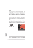 2
2 -
 3
3 -
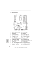 4
4 -
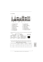 5
5 -
 6
6 -
 7
7 -
8
-
9
-
10
-
11
-
12
-
13
-
14
-
15
-
16
-
17
-
18
-
19
-
20
-
21
-
22
-
23
-
24
-
25
-
26
-
27
-
28
-
29
-
30
-
31
-
32
-
33
-
34
-
35
-
36
-
37
-
38
-
39
-
40
-
41
-
42
-
43
-
44
-
45
-
46
-
47
-
48
-
49
-
50
-
51
-
52
-
53
-
54
-
55
-
56
-
57
-
58
-
59
-
60
-
61
-
62
-
63
-
64
-
65
-
66
-
67
-
68
-
69
-
70
-
71
-
72
-
73
-
74
-
75
-
76
-
77
-
78
-
79
-
80
-
81
-
82
-
83
-
84
-
85
-
86
-
87
-
88
-
89
-
90
-
91
-
92
-
93
-
94
-
95
-
96
-
97
-
98
-
99
-
100
-
101
-
102
-
103
-
104
-
105
-
106
-
107
-
108
-
109
-
110
-
111
-
112
-
113
-
114
-
115
-
116
-
117
-
118
-
119
-
120
-
121
-
122
-
123
-
124
-
125
-
126
-
127
-
128
-
129
-
130
-
131
-
132
-
133
-
134
-
135
-
136
-
137
-
138
-
139
-
140
-
141
-
142
-
143
-
144
-
145
-
146
-
147
-
148
-
149
-
150
-
151
-
152
-
153
-
154
-
155
-
156
-
157
-
158
-
159
-
160
-
161
-
162
-
163
-
164
-
165
-
166
-
167
-
168
-
169
-
170
-
171
-
172
-
173
-
174
-
175
-
176
-
177
-
178
-
179
-
180
-
181
-
182
-
183
-
184
-
185
-
186
-
187
-
188
-
189
-
190
-
191
-
192
-
193
-
194
-
195
-
196
-
197
-
198
-
199
-
200
-
201
-
202
-
203
-
204
-
205
-
206
-
207
-
208
-
209
-
210
-
211
-
212
-
213
-
214
-
215
-
216
-
217
-
218
-
219
-
220
-
221
-
222
-
223
-
224
-
225
-
226
-
227
-
228
-
229
-
230
-
231
-
232
-
233
-
234
-
235
-
236
-
237
-
238
-
239
-
240
-
241
-
242
-
243
-
244
-
245
-
246
-
247
-
248
-
249
-
250
-
251
-
252
-
253
-
254
-
255
-
256
-
257
-
258
-
259
-
260
-
261
-
262
-
263
-
264
-
265
-
266
-
267
-
268
-
269
-
270
-
271
-
272
-
273
-
274
-
275
-
276
-
277
-
278
-
279
-
280
-
281
-
282
-
283
-
284
-
285
-
286
-
287
 |
 |

1
Fatal1ty
990FX
Professional
Series
Motherboard
Who knew that at age 19, I would be a World Champion PC gamer. When I was 13, I
actually played competitive billiards in professional tournaments and won four or five
games off guys who played at the highest level. I actually thought of making a career
of it, but at that young age situations change rapidly. Because I’ve been blessed with
great hand-eye coordination and a grasp of mathematics (an important element in video
gaming) I gravitated to that activity.
GOING PRO
I started professional gaming in 1999 when I entered the CPL (Cyberathlete Professional
League) tournament in Dallas and won $4,000 for coming in third place. Emerging as one
of the top players in the United States, a company interested in sponsoring me
fl
ew me
to Sweden to compete against the top 12 players in the world. I won 18 straight games,
lost none, and took
fi
rst place, becoming the number one ranked Quake III player in the
world in the process. Two months later I followed that success by traveling to Dallas
and defending my title as the world’s best Quake III player, winning the $40,000 grand
prize. From there I entered competitions all over the world, including Singapore, Korea,
Germany, Australia, Holland and Brazil in addition to Los Angeles, New York and St.
Louis.
WINNING STREAK
I was excited to showcase my true gaming skills when defending my title as CPL
Champion of the year at the CPL Winter 2001 because I would be competing in a totally
different first person shooter (fps) game, Alien vs. Predator II. I won that competition
and walked away with a new car. The next year I won the same title playing Unreal
Tournament 2003, becoming the only three-time CPL champion of the year. And I did it
playing a different game each year, something no one else has ever done and a feat of
which I am extremely proud.
At QuakeCon 2002, I faced off against my rival ZeRo4 in one of the most highly
anticipated matches of the year, winning in a 14 to (-1) killer victory. Competing at
Quakecon 2004, I became the World’s 1st Doom3 Champion by defeating Daler in a
series of very challenging matches and earning $25,000 for the victory.
Since then Fatal1ty has traveled the globe to compete against the best in the world,
winning prizes and acclaim, including the 2005 CPL World Tour Championship in New
York City for a $150,000
fi
rst place triumph. In August 2007, Johnathan was awarded the
fi
rst ever Lifetime Achievement Award in the four year history of the eSports-Award for
“showing exceptional sportsmanship, taking part in shaping eSports into what it is today
and for being the prime representative of this young sport. He has become the
fi
gurehead
for eSports worldwide”.
Fatal1ty Story
English