ASRock Fatal1ty X99M Killer Quick Installation Guide
ASRock Fatal1ty X99M Killer Manual
 |
View all ASRock Fatal1ty X99M Killer manuals
Add to My Manuals
Save this manual to your list of manuals |
ASRock Fatal1ty X99M Killer manual content summary:
- ASRock Fatal1ty X99M Killer | Quick Installation Guide - Page 1
change without notice, and should not be constructed as a commitment by ASRock. ASRock assumes no responsibility for any errors or omissions that may appear in CALIFORNIA, USA ONLY he Lithium battery adopted on this motherboard contains Perchlorate, a toxic substance controlled in Perchlorate Best - ASRock Fatal1ty X99M Killer | Quick Installation Guide - Page 2
Manufactured under license under U.S. Patent Nos: 5,956,674; 5,974,380; 6,487,535; 7,003,467 & other U.S. and worldwide patents issued & pending. DTS, the Symbol, & DTS and the Symbol together is a registered trademark & DTS Connect, DTS Interactive, DTS Neo:PC are trademarks of DTS, Inc. Product - ASRock Fatal1ty X99M Killer | Quick Installation Guide - Page 3
the most highly anticipated matches of the year, winning in a 14 to (-1) killer victory. Competing at Quakecon 2004, I became the World's 1st Doom3 Champion by challenging matches and earning $25,000 for the victory. Since then Fatal1ty has traveled the globe to compete against the best in the world - ASRock Fatal1ty X99M Killer | Quick Installation Guide - Page 4
everything gets really nice. It's all about getting the computer processing faster and allowing more luid movement around the maps. My vision for Fatal1ty hardware is to allow gamers to focus on the game without worrying about their equipment, something I've preached since I began competing. I don - ASRock Fatal1ty X99M Killer | Quick Installation Guide - Page 5
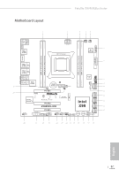
Motherboard Layout Fatal1ty X99M Killer Series 1 2 3 45 USB 2.0 T: USB1 B: USB2 PS2 Keyboard /Mouse CLRC BTN1 USB 2.0 T: USB3 B: USB4 ATX12V1 2011-3 Socket CPU_FAN1 CPU_FAN2 TPMS1 6 Dr. Debug 1 ATXPWR1 DDR4_D1 (64 bit, - ASRock Fatal1ty X99M Killer | Quick Installation Guide - Page 6
CPU Fan Connector (CPU_FAN1) 5 CPU Fan Connector (CPU_FAN2) 6 TPM Header (TPMS1) 7 ATX Power Connector (ATXPWR1) 8 USB 3.0 Header (USB3_5_6) 9 Chassis Fan Connector (CHA_FAN2) 10 28 Front Panel Audio Header (HD_AUDIO1) 29 BIOS Selection Switch (BIOS_SEL1) 30 Power Fan Connector (PWR_FAN1) 2 English - ASRock Fatal1ty X99M Killer | Quick Installation Guide - Page 7
I/O Panel 1 2 Fatal1ty X99M Killer Series 57 3 4 68 16 15 14 13 12 11 10 9 No. Description 1 Fatal1ty Mouse Port (USB1) 2 USB 2.0 Port (USB2) No. Description 9 Microphone (Pink) 10 Optical SPDIF Out Port 3 LAN RJ-45 Port (Intel® I218V)* 11 USB 3.0 Ports (USB3_34) - ASRock Fatal1ty X99M Killer | Quick Installation Guide - Page 8
use the Rear Speaker, Central/Bass, and Front Speaker, or select "Realtek HDA Audio 2nd output" to use the front panel audio. *** he eSATA connector supports SATA with cables within 1 meters. he S_SATA3_3 connector is shared with the eSATA port. English 4 - ASRock Fatal1ty X99M Killer | Quick Installation Guide - Page 9
cards and CPU support list on ASRock's website as well. ASRock website http://www.asrock.com. 1.1 Package Contents • ASRock Fatal1ty X99M Killer Series Motherboard (Micro ATX Form Factor) • ASRock Fatal1ty X99M Killer Series Quick Installation Guide • ASRock Fatal1ty X99M Killer Series Support CD - ASRock Fatal1ty X99M Killer | Quick Installation Guide - Page 10
1.2 Speciications Platform • Micro ATX Form Factor • High Density Glass Fabric PCB CPU • Supports Intel® CoreTM i7 and Xeon® 18-Core Processors Family for the LGA 2011-3 Socket • Digi Power design • 12 Power Phase design • Supports Intel® Turbo Boost 2.0 Technology • Supports Untied Overclocking - ASRock Fatal1ty X99M Killer | Quick Installation Guide - Page 11
Fatal1ty X99M Killer Series Audio LAN Rear Panel I/O • 7.1 CH HD Audio with Content Protection (Realtek ALC1150 Audio Codec) • Premium Blu-ray Audio support • Supports Surge Protection (ASRock Full Spike Protection) • Supports Purity SoundTM 2 - Nichicon Fine Gold Series Audio Caps - 115dB SNR DAC - ASRock Fatal1ty X99M Killer | Quick Installation Guide - Page 12
) (Supports ESD Protection (ASRock Full Spike Protection)) • 1 x Dr. Debug with LED • 1 x Power Switch with LED • 1 x Reset Switch with LED • 1 x BIOS Selection Switch English BIOS Feature • 2 x 128Mb AMI UEFI Legal BIOS with multilingual GUI support (1 x Main BIOS and 1 x Backup BIOS) • Supports - ASRock Fatal1ty X99M Killer | Quick Installation Guide - Page 13
Fatal1ty X99M Killer Series product information, please visit our website: http://www.asrock.com Please realize that there is a certain risk involved with overclocking, including adjusting the setting in the BIOS, applying Untied Overclocking Technology, or using third- - ASRock Fatal1ty X99M Killer | Quick Installation Guide - Page 14
Installation his is a Micro ATX form factor motherboard. Before you install the motherboard, study the coniguration of your chassis to ensure that the motherboard its into it. Pre-installation Precautions Take note of the following precautions before you install motherboard components or change any - ASRock Fatal1ty X99M Killer | Quick Installation Guide - Page 15
Fatal1ty X99M Killer Series 2.1 Installing the CPU 1. Before you insert the 2011 will be seriously damaged. 2. Unplug all power cables before installing the CPU. CAUTION: Please note that X99 platform is only compatible with the LGA 2011-3 socket, which is incompatible with the LGA 2011 socket (for - ASRock Fatal1ty X99M Killer | Quick Installation Guide - Page 16
A 3 B 4 5 12 English - ASRock Fatal1ty X99M Killer | Quick Installation Guide - Page 17
6 7 A B 8 Fatal1ty X99M Killer Series A B English Please save and replace the cover if the processor is removed. he cover must be placed if you wish to return the motherboard for ater service. 13 - ASRock Fatal1ty X99M Killer | Quick Installation Guide - Page 18
2.2 Installing the CPU Fan and Heatsink 1 2 CPU_FAN English 14 - ASRock Fatal1ty X99M Killer | Quick Installation Guide - Page 19
Fatal1ty X99M Killer Series 2.3 Installation of Memory Modules (DIMM) his motherboard provides four 284-pin DDR4 (Double Data Rate 4) DIMM slots, and supports Quad Channel Memory Technology. 1. For quad channel coniguration, you always need to install identical (the same brand, speed, size and - ASRock Fatal1ty X99M Killer | Quick Installation Guide - Page 20
1 2 3 16 English - ASRock Fatal1ty X99M Killer | Quick Installation Guide - Page 21
Fatal1ty X99M Killer Series 2.4 Expansion Slots (PCI Express Slots) here are 3 PCI Express slots on the motherboard. Before installing an expansion better thermal environment, please connect a chassis fan to the motherboard's chassis fan connector (CHA_FAN1 or CHA_FAN2) when using multiple graphics cards - ASRock Fatal1ty X99M Killer | Quick Installation Guide - Page 22
short pin2 and pin3 on CLRCMOS1 for 5 seconds. However, please do not clear the CMOS right ater you update the BIOS. If you need to clear the CMOS when you just inish updating the BIOS, you must boot up the system irst, and then shut it down before you do the clear-CMOS action - ASRock Fatal1ty X99M Killer | Quick Installation Guide - Page 23
Fatal1ty X99M Killer Series 2.6 Onboard Headers and Connectors Onboard headers and connectors are NOT jumpers. Do NOT place jumper caps over these headers and connectors. Placing jumper caps over the headers and connectors will cause permanent damage to the motherboard. System Panel Header (9-pin - ASRock Fatal1ty X99M Killer | Quick Installation Guide - Page 24
GND P+ PUSB_PWR Besides four USB 2.0 ports on the I/O panel, there are two headers on this motherboard. Each USB 2.0 header can support two ports. Vbus IntA_PA_SSRXIntA_PA_SSRX+ GND IntA_PA_SSTXIntA_PA_SSTX+ GND IntA_PA_DIntA_PA_D+ Vbus IntA_PB_SSRXIntA_PB_SSRX+ GND IntA_PB_SSTXIntA_PB_SSTX+ GND - ASRock Fatal1ty X99M Killer | Quick Installation Guide - Page 25
Fatal1ty X99M Killer Series Front Panel Audio Header (9-pin HD_AUDIO1) (see p.1, No. 28) GND PRESENCE# MIC_RET OUT_RET 1 OUT2_L J_SENSE OUT2_R MIC2_R MIC2_L his header is for connecting audio devices to the front audio panel. 1. High Deinition Audio supports Jack Sensing, but the panel wire on - ASRock Fatal1ty X99M Killer | Quick Installation Guide - Page 26
12 24 1 13 8 5 4 1 GND +12V DETECT 1 his motherboard provides a 24-pin ATX power connector. To use a 20-pin ATX power supply, please plug it along Pin 1 and Pin 13. his motherboard provides an 8-pin ATX 12V power connector. To use a 4-pin ATX power supply, please plug it along Pin 1 and Pin - ASRock Fatal1ty X99M Killer | Quick Installation Guide - Page 27
No. 25) TPM Header (17-pin TPMS1) (see p.1, No. 6) Fatal1ty X99M Killer Series RRXD1 DDTR#1 DDSR#1 CCTS#1 1 RRI#1 RRTS#1 GND TTXD1 DDCD#1 his COM1 header supports a serial port module. PCIRST# FRAME PCICLK his connector supports Trusted Platform Module (TPM) system, which can securely store - ASRock Fatal1ty X99M Killer | Quick Installation Guide - Page 28
"Secure Backup UEFI" in the UEFI Setup Utility to duplicate a working copy of the BIOS iles to the primary BIOS to ensure normal system operation. For safety issues, users are not able to update the backup BIOS manually. Users may refer to the BIOS LEDs (BIOS_A_LED or BIOS_ B_LED) to identify which - ASRock Fatal1ty X99M Killer | Quick Installation Guide - Page 29
Fatal1ty X99M Killer Series 2.8 Dr. Debug Dr. Debug is used to provide code information, which makes troubleshooting even easier. Please see the diagrams below for reading the Dr. Debug codes. Code Description 00 Please check if the CPU is installed correctly and then clear CMOS. 0d Problem - ASRock Fatal1ty X99M Killer | Quick Installation Guide - Page 30
or try using other memory modules. d6 he VGA could not be recognized. Please clear CMOS and try re-installing the VGA card. If the problem still exists, please try installing the VGA card in other slots or use other VGA cards. d7 he Keyboard and mouse could not be recognized - ASRock Fatal1ty X99M Killer | Quick Installation Guide - Page 31
Fatal1ty X99M Killer Series 2.9 M.2_SSD (NGFF) Module Installation Guide he M.2, also known as the Next Generation Form Factor (NGFF), is a small size and versatile card edge connector that aims to replace mPCIe and mSATA. - ASRock Fatal1ty X99M Killer | Quick Installation Guide - Page 32
hand. Step 4 Peel of the yellow protective ilm on the nut to be used. Hand tighten the standof into the desired nut location on the motherboard. Step 5 Align and gently insert the M.2 (NGFF) SSD module into the M.2 slot. Please be aware that the M.2 (NGFF) SSD module only its in one orientation - ASRock Fatal1ty X99M Killer | Quick Installation Guide - Page 33
Fatal1ty X99M Killer Series M.2_SSD (NGFF) Module Support List PCIe Interface SATA Interface Plextor PX-AG256M6e Plextor PX- Kingston RBU-SNS8400S3/180GD For the latest updates of M.2_SSD (NFGG) module support list, please visit our website for details: http://www.asrock.com English 29 - ASRock Fatal1ty X99M Killer | Quick Installation Guide - Page 34
2.10 HDD Saver Cable Installation Guide The HDD Saver Connector on this motherboard allows you to switch on and off your SATA HDD(s). * he HDD Saver Connector supports up to two SATA HDDs. 2. Connect one end of the SATA data cable to a SATA port on the motherboard. hen connect the other end to your - ASRock Fatal1ty X99M Killer | Quick Installation Guide - Page 35
der ASRock-Webseite: ASRock-Website http://www.asrock.com. 1.1 Lieferumfang • ASRock Fatal1ty X99M Killer Series - Motherboard (Micro-ATX-Formfaktor) • ASRock Fatal1ty X99M Killer Series - Schnellinstallationsanleitung • ASRock Fatal1ty X99M Killer Series - Support-CD • 1 x E/A-Blendenabschirmung - ASRock Fatal1ty X99M Killer | Quick Installation Guide - Page 36
Daten Plattform • Micro-ATX-Formfaktor • Leiterplatte mit Unterstützt Untied-Übertaktungstechnologie Chipsatz • Intel® X99 Speicher • Vierkanal-DDR4-Speichertechnologie • 4 Sie in der Speicherkompatibilitätsliste auf der ASRock-Webseite. (http:// www.asrock.com/) • Unterstützt ECC-lose RDIMM - ASRock Fatal1ty X99M Killer | Quick Installation Guide - Page 37
Fatal1ty X99M Killer Series Audio LAN Rückblende, E/A • 7.1-Kanal-HD-Audio mit Inhaltsschutz (Realtek ALC1150Audiocodec) • Erstklassige Blu-ray-Audiounterstützung • Unterstützt Überspannungsschutz (ASRock Full Spike Protection) • Unterstützt Purity Sound™ 2 - Nichicon-Audiokappen der Fine Gold- - ASRock Fatal1ty X99M Killer | Quick Installation Guide - Page 38
Technology 13), NCQ, AHCI, Hot-Plugging und ASRock HDD-Saver-Technologie (S_SATA3_3-Anschluss wird mit eSATA- Netzteillüteranschluss (3-polig) • 1 x 24-poliger ATX-Netzanschluss • 1 x 8-poliger 12-V-Netzanschluss ( ützt Schutz gegen elektrostatische Entladung (ASRock Full Spike Protection)) • 1 - ASRock Fatal1ty X99M Killer | Quick Installation Guide - Page 39
Fatal1ty X99M Killer Series BIOSFunktion Hardwareüberwachung Betriebssystem Zertiizierungen • 2 x 128-Mb-AMI-UEFI-Legal-BIOS mit Unterstützung mehrsprachiger graischer Benutzerschnittstellen (1 x HauptBIOS und 1 x Ausfall-BIOS auf unserer Webseite: http://www.asrock.com Bitte beachten Sie, dass - ASRock Fatal1ty X99M Killer | Quick Installation Guide - Page 40
3 an CLRCMOS1 5 Sekunden lang mit einer Jumper-Kappe kurz. Löschen Sie den CMOS jedoch nicht direkt nach der BIOS-Aktualisierung. Falls Sie den CMOS direkt nach Abschluss der BIOS-Aktualisierung löschen müssen, starten Sie das System zunächst; fahren Sie es dann vor der CMOS-Löschung herunter. Bitte - ASRock Fatal1ty X99M Killer | Quick Installation Guide - Page 41
X99M Killer Series 1.4 Integrierte Stiftleisten und Anschlüsse Integrierte Stitleisten und Anschlüsse sind KEINE Jumper. Bringen Sie KEINE Jumper-Kappen an diesen Stitleisten und Anschlüssen an. Durch Anbringen von Jumper-Kappen an diesen Stitleisten und Anschlüssen können Sie das Motherboard - ASRock Fatal1ty X99M Killer | Quick Installation Guide - Page 42
. 24) (9-polig, USB7_8) (siehe S. 1, Nr. 23) USB_PWR PP+ GND DUMMY 1 GND P+ PUSB_PWR Neben vier USB 2.0-Ports an der E/A-Blende beinden sich zwei Stitleisten an diesem Motherboard. Jede USB 2.0-Stitleiste kann zwei Ports unterstützen. Deutsch 38 - ASRock Fatal1ty X99M Killer | Quick Installation Guide - Page 43
Fatal1ty X99M Killer Series USB 3.0-Stitleisten (19-polig, USB3_5_6) (siehe S. 1, Nr. 8) Vbus IntA_PA_SSRXIntA_PA_SSRX+ vier USB 3.0-Ports an der E/A-Blende beindet sich eine Stitleiste an diesem Motherboard. Jede USB 3.0-Stitleiste kann zwei Ports unterstützen. Audiostitleiste (Frontblende) (9- - ASRock Fatal1ty X99M Killer | Quick Installation Guide - Page 44
schließen Sie es zur Nutzung eines 20-poligen ATX-Netzteils entlang Kontakt 1 und Kontakt 13 an. 8 5 Dieses Motherboard bietet einen 8-poligen ATX-12-V-Netzanschluss. 4 1 Bitte schließen Sie es zur Nutzung eines 4-poligen ATX-Netzteils entlang Kontakt 1 und Kontakt 5 an. GND +12V DETECT - ASRock Fatal1ty X99M Killer | Quick Installation Guide - Page 45
Fatal1ty X99M Killer Series hunderboltErweiterungskartenanschluss (5-polig, TBT1) (siehe S. 1, Nr. 26) Serieller-Port-Stitleiste (9-polig, COM1) (siehe S. 1, Nr. 25) TPM-Stitleiste (17-polig, TPMS1) (siehe S. 1, Nr. 6) Bitte verbinden Sie - ASRock Fatal1ty X99M Killer | Quick Installation Guide - Page 46
-Auswahlschalter (BIOS_SEL1) (siehe S. 1, Nr. 29) AB Der BIOS-Auswahlschalter ermöglicht dem System, von BIOS A oder BIOS B zu starten. Dieses Motherboard verfügt über zwei BIOS-Chips, ein primäres BIOS (BIOS_A) und ein Ausfall-BIOS (BIOS_B), die Sicherheit und Stabilität Ihres Systems steigern - ASRock Fatal1ty X99M Killer | Quick Installation Guide - Page 47
Internet de ASRock. Site Internet ASRock http://www.asrock.com. 1.1 Contenu de l'emballage • Carte mère ASRock Fatal1ty X99M Killer Series (facteur de forme Micro ATX) • Guide d'installation rapide ASRock Fatal1ty X99M Killer Series • CD d'assistance ASRock Fatal1ty X99M Killer Series • 1 x panneau - ASRock Fatal1ty X99M Killer | Quick Installation Guide - Page 48
Facteur de forme Micro ATX • PCB Prend en charge la technologie Untied Overclocking Chipset • Intel® X99 Mémoire • Technologie de mémoire quadri-canal DDR4 • 4 charge des mémoires sur le site Web d'ASRock pour de plus amples informations. (http:// www.asrock.com/) • Prend en charge RDIMM non-ECC - ASRock Fatal1ty X99M Killer | Quick Installation Guide - Page 49
Fatal1ty X99M Killer Series Audio Réseau Connectique du panneau arrière • Audio 7.1 CH HD avec protection du contenu (codec audio Realtek ALC1150) • Compatible audio Blu-ray Premium • Protection contre les surtensions (Protection complète contre les pics ASRock) • Prend en charge Purity Sound™ 2 - - ASRock Fatal1ty X99M Killer | Quick Installation Guide - Page 50
, « Hot Plug » et sauvegarde HDD ASRock (le connecteur S_SATA3_3 est partagé avec le • 1 x connecteur d'alimentation ATX 24 broches • 1 x BIOS Français Caractéristiques du BIOS • 2 x BIOS UEFI AMI 128 Mo légaux avec prise en charge interface graphique multilingue (1 x BIOS principal et 1 x BIOS - ASRock Fatal1ty X99M Killer | Quick Installation Guide - Page 51
Fatal1ty X99M Killer Series Surveillance du matériel Système d'exploitation Certiications • Réglage de la notre site : http://www.asrock.com Il est important de signaler que l'overcloking présente certains risques, incluant des modiications du BIOS, l'application d'une technologie d'overclocking - ASRock Fatal1ty X99M Killer | Quick Installation Guide - Page 52
la broche 3 sur CLRCMOS1 pendant 5 secondes. Toutefois, n'efacez pas la CMOS immédiatement après avoir mis à jour le BIOS. Si vous avez besoin d'efacer les données CMOS après une mise à jour du BIOS, vous devez tout d'abord redémarrer le système, puis l'éteindre avant de procéder à l'efacement de la - ASRock Fatal1ty X99M Killer | Quick Installation Guide - Page 53
Fatal1ty X99M Killer Series 1.4 Embases et connecteurs de la carte mère Les embases et connecteurs situés sur la carte NE SONT PAS des cavaliers. Ne placez JAMAIS de - ASRock Fatal1ty X99M Killer | Quick Installation Guide - Page 54
Embase LED d'alimentation (PLED1 à 3 broches) (voir p.1, No. 16) 1 PLEDPLED+ PLED+ Connecteurs Serial ATA3 (S_SATA3_0_1: voir p.1, No. 10) (S_SATA3_2_3: voir p.1, No. 12) (SATA3_0_3: voir p.1, No. 13) (SATA3_1_4: voir p.1, No. 14) (SATA3_2_5: voir p.1, No. 15) SATA3_0 S_SATA3_2 S_SATA3_0 SATA3_3 - ASRock Fatal1ty X99M Killer | Quick Installation Guide - Page 55
Fatal1ty X99M Killer Series compatible avec la HDA pour fonctionner correctement. Veuillez suivre les instructions igurant dans notre manuel et dans le manuel du châssis brancher avec le panneau audio AC'97. E. Pour activer le micro frontal, sélectionnez l'onglet « FrontMic » du panneau de contrôle - ASRock Fatal1ty X99M Killer | Quick Installation Guide - Page 56
broches) (voir p.1, No. 11) 12 24 1 13 8 5 4 1 GND +12V DETECT 1 Cette carte mère est dotée d'un connecteur d'alimentation ATX à 24 broches. Pour utiliser une alimentation ATX à 20 broches, veuillez efectuer les branchements sur la Broche 1 et la Broche 13. Cette carte mère est dotée d'un - ASRock Fatal1ty X99M Killer | Quick Installation Guide - Page 57
Fatal1ty X99M Killer Series Connecteur hunderbolt AIC (TBT1 à 5 broches) (voir p.1, No. 26) Embase pour port série (COM1 à 9 broches) (voir p.1, No. 25) Embase TPM (TPMS1 à 17 broches) (voir p.1, No. 6) - ASRock Fatal1ty X99M Killer | Quick Installation Guide - Page 58
le relais au redémarrage du système. Après cela, utilisez « Secure Backup UEFI » depuis l'utilitaire de coniguration UEFI pour copier les ichiers BIOS vers le BIOS principal et rétablir le fonctionnement normal du système. Par souci de sécurité du système, l'utilisateur ne peut pas mettre à jour le - ASRock Fatal1ty X99M Killer | Quick Installation Guide - Page 59
Sito Web di ASRock http://www.asrock.com. 1.1 Contenuto della confezione • Scheda madre ASRock Fatal1ty X99M Killer Series (Form Factor Micro ATX) • Guida all'installazione rapida di ASRock Fatal1ty X99M Killer Series • CD di supporto di ASRock Fatal1ty X99M Killer Series • 1 x mascherina metallica - ASRock Fatal1ty X99M Killer | Quick Installation Guide - Page 60
Fattore di forma Micro ATX • PBC di 2.0 • Supporta la tecnologia overclocking "slegata" Chipset • Intel® X99 Memoria • Tecnologia memoria DDR4 Quad Channel • 4 x alloggi all'elenco dei supporti di memoria sul sito di ASRock. (http://www.asrock. com/) • Supporta RDIMM non ECC (DIMM registrato - ASRock Fatal1ty X99M Killer | Quick Installation Guide - Page 61
Fatal1ty X99M Killer Series Audio • Audio HD a 7.1 canali con Content Protection (codec audio Realtek ALC1150) • Supporto audio Blu-ray Premium • Supporto protezione da sovratensione (protezione completa ASRock dai picchi di corrente) • Supporto di Purity Sound™ 2 - Cappucci audio Nichicon serie - ASRock Fatal1ty X99M Killer | Quick Installation Guide - Page 62
NCQ, AHCI, Hot Plug e tecnologia ASRock HDD Saver (il connettore S_SATA3_3 è condiviso (3 pin) • 1 x Connettore alimentazione ATX 24 pin • 1 x Connettore alimentazione 12V BIOS Italiano Funzione BIOS • BIOS legale 2 x 128Mb AMI UEFI con supporto GUI multi- lingue (1 x Main BIOS e 1 x Backup BIOS - ASRock Fatal1ty X99M Killer | Quick Installation Guide - Page 63
Fatal1ty X99M Killer Series Hardware Monitor sul prodotto, visitare il nostro sito Web: http://www.asrock.com Prestare attenzione al potenziale rischio previsto nella pratica di overclocking, inclusa la regolazione delle impostazioni nel BIOS, l'applicazione di tecnologia di Untied Overclocking o - ASRock Fatal1ty X99M Killer | Quick Installation Guide - Page 64
il pin2 e il pin3 su CLRCMOS1 per 5 secondi. Tuttavia, non azzerare la CMOS subito dopo aver aggiornato il BIOS. Se è necessario azzerare la CMOS dopo l'aggiornamento del BIOS, è necessario riavviare prima il sistema e in seguito spegnerlo prima di eseguire l'operazione di azzeramento della CMOS. La - ASRock Fatal1ty X99M Killer | Quick Installation Guide - Page 65
Fatal1ty X99M Killer Series 1.4 Header e connettori sulla scheda Gli header e i connettori sulla scheda NON sono jumper. NON posizionare cappucci del jumper su questi header e connettori. Il posizionamento di - ASRock Fatal1ty X99M Killer | Quick Installation Guide - Page 66
Header LED di alimentazione (PLED1 a 3 pin) (vedere pag. 1, n. 16) Connettori Serial ATA3 (S_SATA3_0_1: vedere pag. 1, n. 10) (S_SATA3_2_3: vedere pag.1, n. 12) (SATA3_0_3: vedere pag. 1, n. 13) (SATA3_1_4: vedere pag.1, n. 14) (SATA3_2_5: vedere pag. 1, n. 15) SATA3_0 S_SATA3_2 S_SATA3_0 1 - ASRock Fatal1ty X99M Killer | Quick Installation Guide - Page 67
Fatal1ty X99M Killer Series Header audio pannello anteriore (AUDIO1_HD a 9 pin) (vedere pag. 1, n. 28) GND deve supportare HDA per funzionare correttamente. Seguire le istruzioni presenti nel nostro manuale e nel manuale dello chassis per installare il sistema. 2. Se si utilizza un pannello audio - ASRock Fatal1ty X99M Killer | Quick Installation Guide - Page 68
di collegare una ventola della CPU a 3 pin, collegarla al pin 1-3. Questa scheda madre è dotata di un connettore di alimentazione ATX a 24 pin. Per utilizzare un'alimentazione ATX a 20 pin, collegarla lungo il pin1 e il pin 13. 8 5 Questa scheda madre è dotata di un connettore di alimentazione - ASRock Fatal1ty X99M Killer | Quick Installation Guide - Page 69
Fatal1ty X99M Killer Series Header porta seriale (COM1 a 9 pin) (vedere pag. 1, n. 25) Header TPM (TPMS1 a 17 pin) (vedere pag. 1, n. 6) RRXD1 DDTR#1 DDSR#1 CCTS#1 1 RRI#1 RRTS#1 GND TTXD1 DDCD#1 - ASRock Fatal1ty X99M Killer | Quick Installation Guide - Page 70
è dotata di quattro interruttori intuitivi: Interruttore d'alimentazione, interruttore di ripristino, interruttore Clear CMOS ed un interruttore di selezione BIOS che consentono di accendere/spegnere rapidamente il sistema, ripristinare il sistema, cancellare i valori CMOS oppure eseguire l'avvio su - ASRock Fatal1ty X99M Killer | Quick Installation Guide - Page 71
el sitio web de ASRock. Sitio web de ASRock http://www.asrock.com. 1.1 Contenido del paquete • Placa base ASRock Fatal1ty X99M Killer Series (Factor de forma Micro ATX) • Guía de instalación rápida de ASRock Fatal1ty X99M Killer Series • CD de soporte de ASRock Fatal1ty X99M Killer Series • 1 escudo - ASRock Fatal1ty X99M Killer | Quick Installation Guide - Page 72
Factor de forma Micro ATX • PCB de de aumento de velocidad liberada Conjunto de chips • Intel® X99 Memoria • Tecnología de memoria DDR4 en cuatro canales • 4 consulte la lista de memorias compatibles en el sitio web de ASRock. (http://www.asrock. com/) • Admite RDIMM no ECC (DIMM registrado) • - ASRock Fatal1ty X99M Killer | Quick Installation Guide - Page 73
Fatal1ty X99M Killer Series Audio LAN Panel trasero I/O • 7.1 Audio CH HD con Protección de contenido (Realtek ALC1150 Audio Codec) • Compatible con audio Blu-ray Premium • Compatible con protección por sobretensión (protección ASRock Full Spike) • Compatible con Purity Sound™ 2 - Tapas de audio - ASRock Fatal1ty X99M Killer | Quick Installation Guide - Page 74
y tec- nología de ahorro ASRock HDD (el conector S_SATA3_3 se comparte 3 pines) • 1 Conector de alimentación ATX de 24 pines • 1 Conector de alimentación BIOS Español Función del BIOS • 2 BIOS Legal UEFI AMI de 128Mb compatibles con interfaz gráica de usuario multilingüe (1 BIOS Principal y 1 BIOS - ASRock Fatal1ty X99M Killer | Quick Installation Guide - Page 75
Fatal1ty X99M Killer Series Monitor del hardware SO acerca del producto, visite nuestro sitio web: http://www.asrock.com Tenga en cuenta que existen ciertos riesgos relacionados con ón), incluyendo el ajuste de la coniguración del BIOS, aplicando la Tecnología overcloking no vinculada o utilizando - ASRock Fatal1ty X99M Killer | Quick Installation Guide - Page 76
pin3 en el CLRCMOS1 durante 5 segundos. Sin embargo, no borre el CMOS justo después de que haya actualizado el BIOS. Si necesita borrar el CMOS cuando acabe de actualizar el BIOS, deberá arrancar el sistema primero y, a continuación, deberá apagarlo antes de que realice el borrado del CMOS. Tenga en - ASRock Fatal1ty X99M Killer | Quick Installation Guide - Page 77
Fatal1ty X99M Killer Series 1.4 Conectores y cabezales incorporados Los cabezales y conectores incorporados NO son puentes. NO coloque tapas de puente sobre estos cabezales y conectores. Si coloca tapas de puente - ASRock Fatal1ty X99M Killer | Quick Installation Guide - Page 78
Cabezal de indicador LED de alimentación (PLED1 de 3 pines) (consulte la pág.1, N.º 16) 1 PLEDPLED+ PLED+ Conectores Serie ATA3 (S_SATA3_0_1: consulte la pág.1, N.º 10) (S_SATA3_2_3: (consulte la pág. 1, N.º 12) (SATA3_0_3: consulte la pág.1, N.º 13) (SATA3_1_4: consulte la pág. 1, N.º 14) ( - ASRock Fatal1ty X99M Killer | Quick Installation Guide - Page 79
Fatal1ty X99M Killer Series Cabezal de audio del panel frontal (HD_AUDIO1 de 9 pines) ( compatible con HDA para que pueda funcionar correctamente. Siga las instrucciones que se indican en nuestro manual y en el manual del chasis para instalar su sistema. 2. Si utiliza un panel de audio AC'97, - ASRock Fatal1ty X99M Killer | Quick Installation Guide - Page 80
un ventilador de CPU de 3 pines, conéctelo al Pin 1-3. 12 24 1 13 Esta placa base contiene un conector de alimentación ATX de 24 pines. Para utilizar una toma de alimentación ATX de 20 pines, conéctela en los Pines del 1 al 13. 8 5 Esta placa base contiene un conector de aliment- aci - ASRock Fatal1ty X99M Killer | Quick Installation Guide - Page 81
Fatal1ty X99M Killer Series Cabezal de puerto serie (COM1 de 9 pines) (consulte la pág.1, N.º 25) Cabezal TPM (TPMS1 de 17 pines) (consulte la pág.1, N.º 6) RRXD1 DDTR#1 DDSR#1 CCTS#1 1 RRI#1 RRTS#1 - ASRock Fatal1ty X99M Killer | Quick Installation Guide - Page 82
que el sistema funcione correctamente. Por cuestiones de seguridad, los usuarios no pueden actualizar el BIOS de copia de seguridad manual- mente. Los usuarios deberán consultar los indicadores LED del BIOS (BIOS_A_LED 78 o BIOS_B_LED) para identiicar qué BIOS está activado en ese momento. - ASRock Fatal1ty X99M Killer | Quick Installation Guide - Page 83
Fatal1ty X99M Killer Series 1 ASRock Fatal1ty X99M Killer Series ASRock ASRock BIOS ASRock ASRock VGA ASRock http://www.asrock.com. 1.1 ASRock Fatal1ty X99M Killer Series Micro ATX ASRock Fatal1ty X99M Killer Series ASRock Fatal1ty X99M Killer Series • 1 1 x карты ASRock - ASRock Fatal1ty X99M Killer | Quick Installation Guide - Page 84
® Turbo Boost 2.0 Untied Overclocking Чипсет • Intel® X99 Память Quad Channel DDR4 Memory Technology • 4 DDR4 DIMM DDR4 3000+(OC)*/2933+ (OC)/2800(OC)/2400(OC)/ 2133/1866/ 1600/1333/1066 Non-ECC Unbufered Memory Support List ASRock. (http://www.asrock.com RDIMM DIMM DDR4 ECC RDIMM - ASRock Fatal1ty X99M Killer | Quick Installation Guide - Page 85
Fatal1ty X99M Killer Series Аудио ЛВС • 7.1 HD Audio Realtek ALC1150) Premium Blu-ray Audio ASRock Full Spike Protection Purity Sound™ 2 Nichicon Fine Gold - 115 дБ SNR DAC TI® NE5532 Premium Headset Ampliier 600 Direct Drive DTS • 1 x Intel® I218V (Gigabit LAN - ASRock Fatal1ty X99M Killer | Quick Installation Guide - Page 86
1 x AIC hunderbolt • 2 x USB 2.0 (до 4 USB 2.0 ASRock Full Spike Protection) • 1 x USB 3.0 (до 2 USB 3.0 ASRock Full Spike Protection) • 1 x Dr. Debug 1 x 1 x 1 x BIOS BIOS 82 • 2 x 128 Мб AMI UEFI Legal BIOS 1 x BIOS и 1 x BIOS UEFI ACPI 1.1 SMBIOS 2.3.1 DRAM, PCH 1,05 - ASRock Fatal1ty X99M Killer | Quick Installation Guide - Page 87
Fatal1ty X99M Killer Series 12V, +5V, +3,3V ОС • Microsot® Windows® 8.1 32-bit / 8.1 64-bit / 8 32-bit / 8 64-bit / 7 32-bit / 7 64-bit • FCC, CE, WHQL ErP/EuP ErP/EuP) http://www.asrock.com BIOS Untied Overclocking Technology 32 Windows 4 64 Windows Windows - ASRock Fatal1ty X99M Killer | Quick Installation Guide - Page 88
1.3 3 1 и 2 CMOS (CLRCMOS1 1, № 20) CMOS CLRCMOS1 CMOS 15 2 и 3 на CLRCMOS1 на 5 CMOS BIOS CMOS BIOS CMOS CMOS. CMOS CMOS. 84 - ASRock Fatal1ty X99M Killer | Quick Installation Guide - Page 89
Fatal1ty X99M Killer Series 1.4 9 PANEL1 1, № 17) PLED+ PLEDPWRBTN# GND 1 GND RESET# GND HDLEDHDLED+ PWRBTN RESET PLED S1/S3 S4 S5 HDLED 85 - ASRock Fatal1ty X99M Killer | Quick Installation Guide - Page 90
3 PLED1 1, № 16) Serial ATA3 (S_SATA3_0_1 1, № 10) (S_SATA3_2_3 1, № 12) (SATA3_0_3 1, № 13) (SATA3_1_4 1, № 14) (SATA3_2_5 1, № 15) SATA3_0 S_SATA3_2 S_SATA3_0 1 PLEDPLED+ PLED+ SATA3_3 S_SATA3_3 S_SATA3_1 SATA3 SATA 6,0 eSATA S_SATA3_3 Ultra M.2 Socket S_SATA3_2 RAID - ASRock Fatal1ty X99M Killer | Quick Installation Guide - Page 91
Fatal1ty X99M Killer Series 9 HD_ AUDIO1 1, № 28) GND PRESENCE# MIC_RET OUT_RET 1 OUT2_L J_SENSE OUT2_R MIC2_R MIC2_L 1 HDA 2 AC'97 A Mic_IN (MIC) к MIC2_L. B Audio_R (RIN) к OUT2_R, Audio_L (LIN) к OUT2_L. C - ASRock Fatal1ty X99M Killer | Quick Installation Guide - Page 92
PCIe (4 PCIE_ PWR1 1, № 27) HDD Saver (4 SATA_ PWR_1 1, № 11) 4 3 21 CPU_FAN_SPEED FAN_SPEED_CONTROL GND FAN_VOLTAGE FAN_SPEED 4 3 1-3. 12 24 1 13 24 20 ATX 1 13. 8 5 8 4 1 12 4 ATX, 1 5. GND +12V DETECT 1 4 Molex. HDD Saver. 88 - ASRock Fatal1ty X99M Killer | Quick Installation Guide - Page 93
Fatal1ty X99M Killer Series hunderbolt AIC (5 TBT1 1, № 26) AIC hunderbolt 5 GPIO). 9 COM1 1, № 25) RRXD1 DDTR#1 DDSR#1 CCTS#1 1 RRI#1 RRTS#1 GND TTXD1 DDCD#1 17 TPMS1 1, № 6) PCIRST# FRAME PCICLK Trusted Platform Module (TPM 89 - ASRock Fatal1ty X99M Killer | Quick Installation Guide - Page 94
RSTBTN 1, № 19) Reset CMOS (CLRCBTN 3, № 15) CMOS CMOS. BIOS (BIOS_SEL1 1, № 29) AB BIOS BIOS A или BIOS B. BIOS BIOS (BIOS_A) и BIOS BIOS_B BIOS BIOS BIOS BIOS UEFI Secure Backup UEFI BIOS BIOS BIOS BIOS BIOS (BIOS_A_LED или BIOS_B_LED). 90 - ASRock Fatal1ty X99M Killer | Quick Installation Guide - Page 95
no site da ASRock. Site da ASRock http://www.asrock.com. 1.1 Conteúdo da embalagem • Placa Mãe ASRock Fatal1ty X99M Killer Series (Fator de Forma Micro ATX) • Guia de Instalação Rápida da ASRock Fatal1ty X99M Killer Series • CD de Suporte da ASRock Fatal1ty X99M Killer Series • 1 x Painel de - ASRock Fatal1ty X99M Killer | Quick Installation Guide - Page 96
• Formato Micro ATX • Tecido Boost 2.0 • Suporta a tecnologia Untied Overclocking Chipset • Intel® X99 Memória • Tecnologia de memória DDR4 de quatro canais • Lista de Suporte de Memória no site da ASRock para obter mais informação. (http://www.asrock.com/) • Suporta RDIMM não ECC (DIMM - ASRock Fatal1ty X99M Killer | Quick Installation Guide - Page 97
Fatal1ty X99M Killer Series Português Áudio • Áudio HD de 7.1 canais com proteção de conteúdo (Codec de áudio Realtek ALC1150) • Suporte áudio Blu-ray superior • Suporta proteção contra sobretensão (Proteção Total Contra Picos ASRock) • Suporta Purity Sound™ 2 - Capacitor de Áudio Série Ouro Fino - ASRock Fatal1ty X99M Killer | Quick Installation Guide - Page 98
conector ventilador alimentação (3 pinos) • 1 x conector alimentação ATX 24 pinos • 1 x Conector de energia 8-pinos 12V ( ASRock)) • 1 x Dr. Debug com LED • 1 x Interruptor de alimentação LED • 1 x Interruptor de reinicialização LED • 1 x Interruptor de Seleção de BIOS Funções da BIOS • 2 x BIOS - ASRock Fatal1ty X99M Killer | Quick Installation Guide - Page 99
Fatal1ty X99M Killer Series • Suporta SMBIOS 2.3.1 • Multi-ajuste de tensão de CPU, DRAM, PCH 1,05V visite o nosso site: http://www.asrock.com Por favor, observe que existe um certo risco envolvendo overclocking, incluindo o ajuste das deinições na BIOS, a aplicação de tecnologia Untied - ASRock Fatal1ty X99M Killer | Quick Installation Guide - Page 100
o pino3 no CLRCMOS1 durante 5 segundos. No entanto, não apague o CMOS logo após ter realizado a atualização da BIOS. Se você precisar apagar o CMOS logo após ter terminado uma atualização da BIOS, deverá primeiro iniciar o sistema e voltar a encerrá-lo antes de apagar o CMOS. Por favor, observe que - ASRock Fatal1ty X99M Killer | Quick Installation Guide - Page 101
Fatal1ty X99M Killer Series 1.4 Suportes e conectores onboard Os conectores e suportes onboard NÃO são jumpers. NÃO coloque tampas de jumpers sobre estes terminais e conectores. Colocar tampas de jumpers sobre os terminais e conectores - ASRock Fatal1ty X99M Killer | Quick Installation Guide - Page 102
Suporte LED de alimentação (PLED1 de 3 pinos) (ver p.1, N.º 16) Conectores série ATA3 (S_SATA3_0_1: ver p.1, N.º 10) (S_SATA3_2_3: ver p.1 No. 12) (SATA3_0_3: ver p.1, N.º 13) (SATA3_1_4: ver p.1 No. 14) (SATA3_2_5: ver p.1 No. 15) SATA3_0 S_SATA3_2 S_SATA3_0 1 PLEDPLED+ PLED+ SATA3_3 S_SATA3_3 - ASRock Fatal1ty X99M Killer | Quick Installation Guide - Page 103
Fatal1ty X99M Killer Series Suporte de áudio do painel frontal (HD_AUDIO1 de 9 pinos) (ver p.1, painel no chassi deverá suportar HDA para funcionar corretamente. Por favor, siga as instruções no nosso manual e no manual do chassi para instalar o seu sistema. 2. Se utilizar um painel de áudio AC'97, - ASRock Fatal1ty X99M Killer | Quick Installation Guide - Page 104
de 20 pinos, introduza-a no Pino 1 e Pino 13. 8 5 Esta placa-mãe inclui um conector de alimentação de 12V ATX de 8 pinos. 4 1 Para utilizar uma fonte de alimentação ATX de 4 pinos, introduza-a no Pino 1 e Pino 5. GND +12V DETECT Por favor conecte um cabo de alimentação molex de 4 pinos - ASRock Fatal1ty X99M Killer | Quick Installation Guide - Page 105
Fatal1ty X99M Killer Series Suporte da porta serial (COM1 de 9 pinos) (ver p.1, N.º 25) Suporte TPM (TPMS1 de 17 pinos) (ver p.1, N.º 6) RRXD1 DDTR#1 DDSR#1 CCTS#1 1 RRI#1 RRTS#1 GND TTXD1 - ASRock Fatal1ty X99M Killer | Quick Installation Guide - Page 106
próximo reinício do sistema. Em seguida, utilize "Secure Backup UEFI" no utilitário de coniguração do BIOS para duplicar a cópia de um arquivo BIOS funcional para o BIOS principal para garantir o funcionamento normal do sistema. Por motivos de segurança, os usuários não podem atualizar manualmente - ASRock Fatal1ty X99M Killer | Quick Installation Guide - Page 107
destek listelerini de ASRock'ın web sitesinden bulabilirsiniz. ASRock web sitesi http://www.asrock.com. 1.1 Ambalaj İçeriği • ASRock Fatal1ty X99M Killer Series Anakartı (Micro ATX Form Faktörü) • ASRock Fatal1ty X99M Killer Series Hızlı Kurulum Kılavuzu • ASRock Fatal1ty X99M Killer Series Destek - ASRock Fatal1ty X99M Killer | Quick Installation Guide - Page 108
Platform • Micro ATX Form Faktörü • Untied Overclocking Teknolojisini destekler Yonga kümesi • Intel® X99 Bellek • Dört Kanallı DDR4 Bellek Teknolojisi • 4 destekler * Ayrıntılı bilgi için ASRock'ın web sitesindeki Bellek Desteği Listesine bakın. (http://www.asrock.com/) • ECC-dışı RDIMM Desteği - ASRock Fatal1ty X99M Killer | Quick Installation Guide - Page 109
Fatal1ty X99M Killer Series Ses LAN Arka Panel I/O • İçerik Koruma Özelliği ile 7.1 CH HD Ses (Realtek ALC1150 Ses Codec Bileşeni) • Üstün Blu-ray Ses desteği • Dalgalanma Koruması Destekler (ASRock Tam Ani Gerilim Koruması) • Purity Sound™ 2 destekler - Nichicon Fine Gold Serisi Ses Kapakları - - ASRock Fatal1ty X99M Killer | Quick Installation Guide - Page 110
AHCI, Tak Çıkar ve ASRock Sabit Disk Kaydedici Teknolojisi destekler Kontrolü) • 1 x Güç Fanı Bağlayıcısı (3 pimli) • 1 x 24 pim ATX Güç Bağlayıcısı • 1 x 8 pim 12V Güç Bağlayıcısı (Yüksek Yoğunluklu lantı noktası destek- ler) (ESD Koruması Destekler (ASRock Tam Ani Gerilim Koruması)) • 1 x USB 3.0 Ba - ASRock Fatal1ty X99M Killer | Quick Installation Guide - Page 111
Fatal1ty X99M Killer Series BIOS Özelliği Donanım Monitörü OS Belgeler • Çok dilli GUI desteğiyle 2 x 128Mb AMI UEFI Legal BIOS (1 x Ana BIOS ve 1 x Yedek BIOS için, lütfen web sitemizi ziyaret edin: http://www.asrock.com Lütfen, BIOS ayarlarını düzenleme, Bağımsız Hız Aşırtma Teknolojinin - ASRock Fatal1ty X99M Killer | Quick Installation Guide - Page 112
, CLRCMOS1 üzerindeki pin2 ve pin3'ü 5 saniye boyunca kısaltmak için bir bağlantı teli kullanın. Ancak, CMOS'u lütfen BIOS'u güncelledikten hemen sonra temizlemeyin. BIOS'u güncelledikten hemen sonra CMOS'u temizlemeniz gerekirse, önce sistemi başlatın ve ardından CMOS temizleme işlemi öncesinde - ASRock Fatal1ty X99M Killer | Quick Installation Guide - Page 113
Fatal1ty X99M Killer Series 1.4 Ekli Bağlantılar ve Bağlayıcılar Ekli bağlantılar ve bağlayıcılar bağlantı teli değildir. Bağlantı teli - ASRock Fatal1ty X99M Killer | Quick Installation Guide - Page 114
Güç LED Bağlantısı (3-pin PLED1) (bkz. sf.1, No. 16) Seri ATA3 Bağlayıcıları (S_SATA3_0_1: bkz. sf.1, No. 10) (S_SATA3_2_3: bkz. s.1 No. 12) (SATA3_0_3: bkz. sf.1, No. 13) (SATA3_1_4: bkz. s.1 No. 14) (SATA3_2_5: bkz. s.1 No. 15) SATA3_0 S_SATA3_2 S_SATA3_0 1 PLEDPLED+ PLED+ SATA3_3 S_SATA3_3 - ASRock Fatal1ty X99M Killer | Quick Installation Guide - Page 115
Fatal1ty X99M Killer Series USB 3.0 Bağlantıları (19-pin USB3_5_6) (bkz. sf.1, No. 8) Vbus IntA_PA_SSRXIntA_PA_SSRX+ GND IntA_PA_SSTXIntA_PA_SSTX+ GND IntA_PA_DIntA_PA_D+ Vbus IntA_PB_SSRXIntA_PB_SSRX+ GND IntA_PB_SSTXIntA_PB_SSTX+ GND IntA_PB_DIntA_PB_D+ Dummy 1 Bu - ASRock Fatal1ty X99M Killer | Quick Installation Guide - Page 116
edilebilir. CPU Fan Bağlayıcıları (4-pin CPU_FAN1) (bkz sf.1, No. 4) (3-pin CPU_FAN2) (bkz sf.1, No. 5) ATX Güç Bağlayıcısı (24-pin ATXPWR1) (bkz. sf.1, No. 7) ATX 12V Güç Bağlayıcısı (8-pin ATX12V1) (bkz. sf.1, No. 2) 4 3 21 CPU_FAN_SPEED FAN_SPEED_CONTROL GND FAN_VOLTAGE FAN_SPEED Bu anakart - ASRock Fatal1ty X99M Killer | Quick Installation Guide - Page 117
Fatal1ty X99M Killer Series PCIe Güç Bağlayıcısı (4 pimli PCIE_PWR1) (bkz. sf.1, No. 27) Sabit Disk Kaydedici Bağlayıcısı (4 pimli SATA_PWR_1) (bkz. sf.1, No. 11) hunderbolt AIC Bağlayıcısı (5 - ASRock Fatal1ty X99M Killer | Quick Installation Guide - Page 118
. Bu işlev yalnızca bilgisayarınızı kapattığınızda ve işini prizden çektiğinizde çalışır. Türkçe BIOS Seçim Anahtarı (BIOS_SEL1) (bkz. s.1, No. 29) AB BIOS Seçim Anahtarı sistemin BIOS A veya BIOS B'den önyüklenmesini sağlar. Bu anakartta sisteminizin güvenliğini ve kararlılığını artıran ana - ASRock Fatal1ty X99M Killer | Quick Installation Guide - Page 119
한국어 Fatal1ty X99M Killer Series 1 개요 ASRock Fatal1ty X99M Killer Series ASRock ASRock BIOS ASRock ASRock VGA 카드와 CPU ASRock http://www.asrock.com. 1.1 • ASRock Fatal1ty X99M Killer Series Micro ATX ASRock Fatal1ty X99M Killer Series ASRock Fatal1ty X99M Killer Series 지원 CD • I/O 1 - ASRock Fatal1ty X99M Killer | Quick Installation Guide - Page 120
규격 플랫폼 CPU • Micro ATX PCB • LGA 2011-3 소켓용 Intel® CoreTM i7 및 Xeon® 18 • Digi 12 Intel® Turbo Boost 2.0 Untied Overclocking • Intel® X99 • Quad Channel DDR4 DDR4 DIMM 슬롯 4 개 • DDR4 3000+(OC)*/2933+(OC)/2800(OC)/2400 (OC)/2133/1866/ 1600/1333/1066 비 -ECC ASRock http://www.asrock.com - ASRock Fatal1ty X99M Killer | Quick Installation Guide - Page 121
Fatal1ty X99M Killer Series 한국어 오디오 LAN I/O 7.1 CH HD Realtek ALC1150 Blu-ray ASRock Purity Sound ™ 2 지원 - Nichicon Fine Gold 115dB SNR DAC - TI® NE5532 600 EMI PCB DTS • 1 x Intel® I218V (Gigabit LAN PHY 10/100/1000 Mb/s) • 1 x Qualcomm® Atheros® - ASRock Fatal1ty X99M Killer | Quick Installation Guide - Page 122
핀 ) • 24 핀 ATX 1 개 • 8 핀 12V 1 HDD 1 개 • PCIe 1 1 개 • hunderbolt AIC 커넥터 1 개 • USB 2.0 헤더 2 개 (USB 2.0 포트 4 ESD (ASRock USB 3.0 헤더 1 개 (USB 3.0 포트 2 ESD 보호 (ASRock LED 탑재 Dr. Debug 1 개 • LED 1 개 • LED 1 개 • BIOS 1 개 GUI 지원 128Mb AMI UEFI Legal BIOS 2 BIOS 1 BIOS 1 개 ) UEFI ACPI - ASRock Fatal1ty X99M Killer | Quick Installation Guide - Page 123
Fatal1ty X99M Killer Series • CPU CPU CPU CPU CPU 12V, +5V, +3.3V, CPU CPU 내 부 전압 OS • Microsot® Windows® 8.1 32 비트 / 8.1 64 비트 / 8 32 비트 / 8 64 비트 / 7 32 비트 / 7 64 비트 인증 • FCC, CE, WHQL • ErP/EuP ErP/EuP 요) http://www.asrock.com BIOS Untied Overclocking Technology - ASRock Fatal1ty X99M Killer | Quick Installation Guide - Page 124
1.3 3 1 과 핀 2 Clear CMOS 점퍼 (CLRCMOS1) (1 20 기본값 Clear CMOS CLRCMOS1 CMOS 15 CLRCMOS1 의 핀 2 와 핀 3 을 5 BIOS CMOS BIOS CMOS CMOS CMOS Clear CMOS Clear CMOS 한 국 어 120 - ASRock Fatal1ty X99M Killer | Quick Installation Guide - Page 125
Fatal1ty X99M Killer Series 1.4 (9 핀 PANEL1) (1 17 PLED+ PLEDPWRBTN# GND 1 GND RESET# GND HDLEDHDLED+ PWRBTN RESET PLED LED LED S1/S3 LED S4 S5 LED HDLED LED LED LED LED LED 한국어 121 - ASRock Fatal1ty X99M Killer | Quick Installation Guide - Page 126
전원 LED 헤더 (3 핀 PLED1) (1 16 시리얼 ATA3 커넥터 (S_SATA3_0_1: (1 10 S_SATA3_2_3: (1 12 SATA3_0_3: (1 13 SATA3_1_4: (1 14 SATA3_2_5: (1 15 SATA3_0 S_SATA3_2 S_SATA3_0 1 PLEDPLED+ PLED+ SATA3_3 S_SATA3_3 S_SATA3_1 LED SATA3 6.0 Gb/s SATA I/O 의 eSATA S_SATA3_3 M.2 S_SATA3_2 RAID - ASRock Fatal1ty X99M Killer | Quick Installation Guide - Page 127
한국어 Fatal1ty X99M Killer Series (9 핀 HD_AUDIO1) (1 28 GND PRESENCE# MIC_RET OUT_RET 1 OUT2_L J_SENSE OUT2_R MIC2_R MIC2_L 1 HDA 2. ACí 97 A. Mic_IN (MIC) 를 MIC2_L B. Audio_R (RIN) 을 OUT2_R Audio_L (LIN) 을 OUT2_L C. 접지 (GND - ASRock Fatal1ty X99M Killer | Quick Installation Guide - Page 128
hunderbolt AIC 커넥터 (5 핀 TBT1) (1 26 4 3 21 CPU_FAN_SPEED FAN_SPEED_CONTROL GND FAN_VOLTAGE FAN_SPEED 12 24 1 13 8 5 4 1 4 핀 CPU 3 핀 CPU 1-3 24 핀 ATX 20 핀 ATX 1 과 핀 13 8 핀 ATX 12V 4 핀 ATX 1 과 핀 5 GND +12V DETECT 1 3 4 HDD HDD hunderboltTM AIC 5 GPIO 124 - ASRock Fatal1ty X99M Killer | Quick Installation Guide - Page 129
Fatal1ty X99M Killer Series (9 핀 COM1) (1 25 RRXD1 DDTR#1 DDSR#1 CCTS#1 1 RRI#1 RRTS#1 GND TTXD1 DDCD#1 TPM 헤더 (17 핀 TPMS1) (1 6 PCIRST# FRAME PCICLK TPM(Trusted Platform Module TPM 한국어 125 - ASRock Fatal1ty X99M Killer | Quick Installation Guide - Page 130
CMOS BIOS CMOS BIOS PWRBTN) (1 18 Power RSTBTN) (1 19 Reset CMOS CLRCBTN) (3 15 CMOS CMOS BIOS BIOS_SEL1) (1 29 AB BIOS BIOS A 또는 BIOS B BIOS BIOS (BIOS_A BIOS (BIOS_B BIOS BIOS BIOS B BIOS UEFI Setup Utility UEFI BIOS BIOS BIOS BIOS - ASRock Fatal1ty X99M Killer | Quick Installation Guide - Page 131
日本語 Fatal1ty X99M Killer Series 1 ͡Ίʹ ASRock Fatal1ty X99M Killer Series ASRock Fatal1ty X99M Killer Series ASRock ASRock BIOS VGA CPU http://www.asrock.com. 1.1 • ASRock Fatal1ty X99M Killer Series ATX ASRock Fatal1ty X99M Killer Series ASRock Fatal1ty X99M Killer Series αϙʔτ CD • - ASRock Fatal1ty X99M Killer | Quick Installation Guide - Page 132
日本語 1.2 仕様 ATX PCB CPU • LGA 2011-3 Intel® CoreTM i7 ͓Αͼ Xeon® 18-Core 12 Intel 2.0 Untied Overclocking Λαϙʔτ • Intel® X99 DDR4 4 x DDR4 DIMM DDR4 3000+(OC)*/2933+(OC)/2800(OC)/2400 (OC)/2133/ 1866/1600/1333/1066 ϊϯ ECC ASRock http://www.asrock.com/) • ϊϯ ECC RDIMM DIMM - ASRock Fatal1ty X99M Killer | Quick Installation Guide - Page 133
Fatal1ty X99M Killer Series 日本語 ΦʔσΟΦ LAN ϦΞύωϧ I/O • 7.1 CH HD Realtek ALC1150 ASRock Purity Sound ™ 2 ʹରԠ - SN ൺ 115dB ͷ DAC TI® NE5532 600 Ohms EMI PCB DTS • 1 x Intel® I218V LAN PHY 10/100/1000 Mb/ ඵ ) • 1 x Qualcomm® Atheros® KillerTM E2200 γϦʔζʢPCIE - ASRock Fatal1ty X99M Killer | Quick Installation Guide - Page 134
ϐϯ ATX 1 x 8 ϐϯ 12V 1 x HDD 1 x PCIe 1 x 1 x hunderbolt AIC 2 x USB 2.0 ϔομʔʢ4 ݸͷ USB 2.0 ESD ASRock 1 x USB 3.0 ϔομʔʢ2 ݸͷ USB 3.0 ESD ASRock 1 x Dr. DebugɺLED ͖ • 1 x LED ͖ • 1 x LED ͖ • 1 x BIOS • 2 x 128Mb AMI UEFI Legal BIOS GUI αϙʔτ ʢ1 x ϝΠϯ BIOS ͱ 1 x BIOS - ASRock Fatal1ty X99M Killer | Quick Installation Guide - Page 135
日本語 Fatal1ty X99M Killer Series OS ೝূ • SMBIOS 2.3.1 CPUɺDRAMɺPCH 1.05VɺPCH 1.5V, VPPM ෳిѹ ઃఆ • CPU CPU CPU CPU CPU 12Vɺ+5Vɺ+3. Ϗοτ / 8 64 Ϗοτ / 7 32 Ϗοτ / 7 64 Ϗοτ • FCCɺCEɺWHQL • ErP/EuP Readʢy ErP/EuP ready http://www.asrock.com BIOS Windows® 32 4GB Windows® 64 Windows - ASRock Fatal1ty X99M Killer | Quick Installation Guide - Page 136
日本語 1.3 3 1 ͱϐϯ 2 CMOS CLRCMOS1) ʢp.1ɺNo. 20 ࢀরʣ σϑΥϧτ CMOS ͷ ΫϦΞ CLRCMOS1 ɺCMOS 15 CLRCMOS1 ͷϐ ϯ 2 ͱϐϯ 3 5 BIOS CMOS BIOS CMOS CMOS CMOS CMOS CMOS 132 - ASRock Fatal1ty X99M Killer | Quick Installation Guide - Page 137
日本語 Fatal1ty X99M Killer Series 1.4 9 ϐϯύωϧ 1ʣ ʢp.1ɺNo. 17 ࢀরʣ PLED+ PLEDPWRBTN# GND 1 GND RESET# GND HDLEDHDLED+ PWRBTN RESET PLED LED LED S1/S3 LED S4 S5 LED HDLED LED LED LED LED LED 133 - ASRock Fatal1ty X99M Killer | Quick Installation Guide - Page 138
ి ݯLED ϔομʔ ʢ3 ϐϯ PLED1ʣ ʢp.1ɺNo. 16 ࢀরʣ γϦΞϧ ATA3 S_SATA3_0_1: p.1ɺNo. 10 ࢀরʣ (S_SATA3_2_3: p.1ɺNo. 12 ࢀরʣ (SATA3_0_3: p.1ɺNo. 13 ࢀরʣ (SATA3_1_4: p.1ɺNo. 14 ࢀরʣ (SATA3_2_5: p.1ɺNo. 15 ࢀরʣ SATA3_0 S_SATA3_2 S_SATA3_0 1 PLEDPLED+ PLED+ SATA3_3 S_SATA3_3 S_SATA3_1 LED ͜ΕΒ 10 SATA3 6.0 Gb - ASRock Fatal1ty X99M Killer | Quick Installation Guide - Page 139
日本語 Fatal1ty X99M Killer Series 9 ϐϯ HD_AUDIO1ʣ ʢp.1ɺNo. 28 ࢀরʣ GND PRESENCE# MIC_RET OUT_RET 1 OUT2_L J_SENSE OUT2_R MIC2_R MIC2_L 1 HDA 2. AC`97 A. Mic_IN (MIC) Λ MIC2_L B. Audio_R (RIN) Λ OUT2_R ʹɺAudio_L (LIN) Λ OUT2_L C. Ξʔε ( - ASRock Fatal1ty X99M Killer | Quick Installation Guide - Page 140
4 3 21 CPU_FAN_SPEED FAN_SPEED_CONTROL GND FAN_VOLTAGE FAN_SPEED 4 ϐ ϯ CPU 3 ϐϯͷ CPU 1-3 12 24 1 13 24 ϐ ϯ ATX 20 ϐϯͷ ATX 1 ͱ 13 8 5 8 ϐ ϯ ATX12V 4 ϐϯ 4 1 ͷ ATX ʹɺϐϯ 1 ͱ 5 ൪ʹ߹ GND +12V DETECT 1 3 4 HDD HDD hunderbolt AIC ίωΫλ ʢ5 ϐϯ TBT1ʣ ʢp.1ɺNo. 26 - ASRock Fatal1ty X99M Killer | Quick Installation Guide - Page 141
Fatal1ty X99M Killer Series 9 ϐϯ COM1ʣ ʢp.1ɺNo. 25 ࢀরʣ TPM ϔομʔ ʢ17 ϐϯ TPMS1ʣ ʢp.1ɺNo. 6 ࢀরʣ RRXD1 DDTR#1 DDSR#1 CCTS#1 1 RRI#1 RRTS#1 GND TTXD1 DDCD#1 PCIRST# FRAME PCICLK TPM TPM 日本語 137 - ASRock Fatal1ty X99M Killer | Quick Installation Guide - Page 142
RSTBTNʣ ʢp.1ɺNo. 19 ࢀরʣ Reset ΫϦΞ CMOS εΠον ʢCLRCBTNʣ ʢp.3ɺNo. 15 ࢀরʣ ΫϦΞ CMOS CMOS BIOS BIOS_SEL1) ʢp.1ɺNo. 29 ࢀরʣ AB BIOS BIOS A ·ͨ BIOS B BIOʢS BIOS_A BIOʢS BIOS_Bʣͷ 2 ͭͷ BIOS BIOS BIOS BIOS B BIOS BIOS UEFI BIOS BIOS BIOS BIOS LEDʢBIOS_A_LED ·ͨ BIOS_B_LED - ASRock Fatal1ty X99M Killer | Quick Installation Guide - Page 143
简体中文 Fatal1ty X99M Killer Series 1 简介 Fatal1ty X99M Killer BIOS VGA 卡和 CPU http://www.asrock.com. 1.1 • 华擎 Fatal1ty X99M Killer Micro ATX Fatal1ty X99M Killer Fatal1ty X99M Killer 1 x I/O 面板 • 1 x 华擎 SLI_Bridge 卡 • 2 x 串行 ATA (SATA 1 x HDD Saver 线 • 1 x Ultra M.2 139 - ASRock Fatal1ty X99M Killer | Quick Installation Guide - Page 144
规格 平台 CPU 扩充槽 • Micro ATX LGA 2011-3 Socket 的 Intel® CoreTM i7 and Xeon® 18 12 相 CPU Intel® Turbo Boost 2.0 • Intel® X99 DDR4 4 x DDR4 DIMM DDR4 3000+(OC)*/2933+(OC)/2800(OC)/2400(OC)/ 2133/1866/1600/1333/1066 非 ECC Memory Support List http://www.asrock.com ECC RDIMM DIMM LGA - ASRock Fatal1ty X99M Killer | Quick Installation Guide - Page 145
简体中文 Fatal1ty X99M Killer Series 音频 LAN 后面板 I/O 7.1 CH Realtek ALC1150 • 优质 Blu-ray 2 代 - Nichicon 115dB TI® NE5532 3az • 支持 PXE • 1 x PS/2 1 x 光学 SPDIF 1 x eSATA 接口 • 3 x USB 2.0 ESD 1 x Fatal1ty USB 2.0 ESD 4 x USB 3.0 ESD 2 x RJ-45 LAN LED(ACT/LINK LED 和 SPEED LED) • 1 x 清除 - ASRock Fatal1ty X99M Killer | Quick Installation Guide - Page 146
x 3 1 x 3 针) • 1 x 24 针 ATX 1 x 8 针 12V 1 x 1 x PCIe 1 x 1 x 2 x USB 2.0 4 个 USB 2.0 ESD 静 1 x USB 3.0 2 个 USB 3.0 ESD 静 1 x Dr. Debug LED • 1 x LED • 1 x LED • 1 x BIOS • 2 x128Mb AMI UEFI Legal BIOS GUI 支持 (1 x 主 BIOS 和 1 x 备份 BIOS) UEFI 技术 • ACPI 1.1 SMBIOS 2.3.1 支持 • CPU - ASRock Fatal1ty X99M Killer | Quick Installation Guide - Page 147
简体中文 Fatal1ty X99M Killer Series 硬件监控 • CPU CPU CPU CPU CPU 12V、+5V、+3.3V、CPU CPU 内 部电压 • Microsot® Windows® 8.1 32-bit / 8.1 64-bit / 8 32-bit / 8 64-bit / 7 32-bit / 7 64-bit • FCC、CE、WHQL • ErP/EuP ErP/EuP http://www.asrock.com BIOS 4GB Windows® 32-bit Windows® 64- - ASRock Fatal1ty X99M Killer | Quick Installation Guide - Page 148
简体中文 1.3 3 1 和针脚 2 清除 CMOS 跳线 (CLRCMOS1) (见第 1 页,第 20 个) 默认 清除 CMOS CLRCMOS1 CMOS 15 CLRCMOS1 2 和针脚 3 短接 5 BIOS CMOS BIOS CMOS CMOS CMOS 清除 CMOS CMOS 144 - ASRock Fatal1ty X99M Killer | Quick Installation Guide - Page 149
简体中文 Fatal1ty X99M Killer Series 1.4 9 针 PANEL1) ( 见第 1 页,第 17 个) PLED+ PLEDPWRBTN# GND 1 GND RESET# GND HDLEDHDLED+ PWRBTN RESET PLED LED LED S1/S3 LED S4 S5 LED 熄灭。 HDLED LED LED LED 亮起。 LED LED 145 - ASRock Fatal1ty X99M Killer | Quick Installation Guide - Page 150
电源 LED 接脚 (3 针 PLED1) (见第 1 页,第 16 个) 1 PLEDPLED+ PLED+ LED SATA3_3 S_SATA3_3 S_SATA3_1 SATA3_0 S_SATA3_2 S_SATA3_0 串行 ATA3 接口 (S_SATA3_0_1: 见第 1 页,第 10 个) (S_SATA3_2_3: 见第 1 页,第 12 个) (SATA3_0_3: 见第 1 页,第 13 个) (SATA3_1_4: 见第 1 页,第 14 个) (SATA3_2_5: 见第 1 页,第 15 个) 这十个 SATA3 6.0 Gb/s - ASRock Fatal1ty X99M Killer | Quick Installation Guide - Page 151
简体中文 Fatal1ty X99M Killer Series 9 针 HD_AUDIO1) (见第 1 页,第 28 个) GND PRESENCE# MIC_RET OUT_RET 1 OUT2_L J_SENSE OUT2_R MIC2_R MIC2_L 1 HDA 2 AC'97 A. 将 Mic_IN (MIC) 连接到 MIC2_L。 B. 将 Audio_R (RIN) 连接到 OUT2_R,将 Audio_L (LIN) 连接到 OUT2_L。 C GND - ASRock Fatal1ty X99M Killer | Quick Installation Guide - Page 152
针 ATXPWR1) (见第 1 页,第 7 个) 4 3 21 CPU_FAN_SPEED FAN_SPEED_CONTROL GND FAN_VOLTAGE FAN_SPEED 12 24 1 13 4 针 CPU 3 针 CPU 1-3。 24 针 ATX 20 针 ATX 1 和针脚 13 ATX 12V 8 针 ATX12V1) (见第 1 页,第 2 个) PCIe 4- 针 PCIE_PWR1 1 页,第 27 个) 4- 针 SATA_PWR_1 1 页,第 11 个) 8 5 4 1 GND +12V DETECT - ASRock Fatal1ty X99M Killer | Quick Installation Guide - Page 153
Fatal1ty X99M Killer Series 9 针 COM1) (见第 1 页,第 25 个) RRXD1 DDTR#1 DDSR#1 CCTS#1 1 RRI#1 RRTS#1 GND TTXD1 DDCD#1 TPM 接脚 (17 针 TPMS1) (见第 1 页,第 6 个) PCIRST# FRAME PCICLK Trusted Platform Module TPM TPM 简体中文 149 - ASRock Fatal1ty X99M Killer | Quick Installation Guide - Page 154
RSTBTN 1 页,第 19 个) Reset 清除 CMOS 开关 (CLRCBTN 3 页,第 15 个) 清除 CMOS CMOS 值。 BIOS BIOS_SEL1 1 页,第 29 个) AB BIOS BIOS A 或 BIOS B BIOS BIOS (BIOS_A BIOS (BIOS_B BIOS BIOS BIOS B BIOS UEFI Setup Utility UEFI"将 BIOS BIOS BIOS BIOS LED (BIOS_A_LED 或 BIOS_B_LED - ASRock Fatal1ty X99M Killer | Quick Installation Guide - Page 155
简体中文 Fatal1ty X99M Killer Series SJ/T 11364-2006 10 年。 圖一 部件名稱 鉛 (Pb) 鎘 (Cd) 汞 (Hg Cr(VI PBB PBDE) X O O O O O X O O O O O O SJ/T 11363-2006 X SJ/T 11363-2006 2002/95/EC 151 - ASRock Fatal1ty X99M Killer | Quick Installation Guide - Page 156
繁體中文 1 簡介 Fatal1ty X99M Killer BIOS VGA 卡及 CPU http://www.asrock.com 1.1 • 華擎 Fatal1ty X99M Killer Micro ATX Fatal1ty X99M Killer Fatal1ty X99M Killer 1 x I/O 1 x ASRock SLI_Bridge 卡 • 2 x Serial ATA (SATA 1 x HDD Saver 纜線 • 1 x Ultra M.2 插座) 152 - ASRock Fatal1ty X99M Killer | Quick Installation Guide - Page 157
繁體中文 Fatal1ty X99M Killer Series 1.2 規格 平台 CPU 擴充插槽 • Micro ATX • 支援 LGA 2011-3 插座的 Intel® CoreTM i7 與 Xeon® 18 Digi Power) • 12 Intel® Turbo Boost 2.0 • Intel® X99 DDR4 4 x DDR4 DIMM DDR4 3000+(OC)*/2933+(OC)/2800(OC)/2400(OC)/ 2133/1866/1600/1333/1066 非 ECC http:// www.asrock. - ASRock Fatal1ty X99M Killer | Quick Installation Guide - Page 158
® Security Wake On Internet 技術 (Qualcomm® Atheros® KillerTM E2200 ESD Energy Eicient Ethernet 802.3az • 支援 PXE • 1 x PS/2 1 x 光纖 SPDIF 1 x eSATA 接頭 • 3 x USB 2.0 ESD 1 x Fatal1ty USB 2.0 ESD 4 x USB 3.0 ESD 2 x RJ-45 LAN LED(ACT/LINK LED 及 SPEED LED) • 1 x 清除 CMOS 開關 • HD 154 - ASRock Fatal1ty X99M Killer | Quick Installation Guide - Page 159
Fatal1ty X99M Killer Series 繁體中文 BIOS 功能 • 10 x SATA3 6.0 Gb/s RAID(RAID 0、RAID 1、RAID 5、RAID 排針 • 2 x CPU 1 x 4-pin、1 x 3-pin) • 2 x 1 x 4-pin、1 x 3-pin 1 x 3-pin) • 1 x 24 pin ATX 1 x 8 pin 12V 1 x 1 x PCIe 1 x 1 x hunderbolt AIC 2 x USB 2.0 4 個 USB 2.0 ESD 1 x USB 3.0 2 個 - ASRock Fatal1ty X99M Killer | Quick Installation Guide - Page 160
度) • CPU 12V、+5V、+3.3V、CPU CPU 內部電壓 作業系統 • Microsot® Windows® 8.1 32 位元 / 8.1 64 位元 / 8 32 位元 / 8 64 位元 / 7 32 位元 / 7 64 位元 認證 • FCC、CE、WHQL • ErP/EuP Ready ErP/EuP ready http://www.asrock.com BIOS 在 Windows® 32 4GB。Windows® 64 XFast RAM 運用 Windows 156 - ASRock Fatal1ty X99M Killer | Quick Installation Guide - Page 161
繁體中文 Fatal1ty X99M Killer Series 1.3 3-pin pin1 及 pin2 清除 CMOS 跳線 (CLRCMOS1 1 20) 預設 清除 CMOS CLRCMOS1 清除 CMOS 15 CLRCMOS1 上的 pin2 及 pin3 短路約 5 BIOS CMOS BIOS CMOS CMOS CMOS 清除 CMOS CMOS 157 - ASRock Fatal1ty X99M Killer | Quick Installation Guide - Page 162
繁體中文 1.4 9-pin PANEL1 1 17) PLED+ PLEDPWRBTN# GND 1 GND RESET# GND HDLEDHDLED+ PWRBTN RESET PLED LED LED S1/S3 LED S4 S5) 時,LED HDLED LED LED LED LED LED 158 - ASRock Fatal1ty X99M Killer | Quick Installation Guide - Page 163
繁體中文 Fatal1ty X99M Killer Series 電源 LED 排針 (3-pin PLED1 1 16) Serial ATA3 接頭 (S_SATA3_0_1 1 10) (S_SATA3_2_3 1 12) (SATA3_0_3 1 13) (SATA3_1_4 1 14) (SATA3_2_5 1 15) SATA3_0 S_SATA3_2 S_SATA3_0 1 PLEDPLED+ PLED+ SATA3_3 S_SATA3_3 S_SATA3_1 - ASRock Fatal1ty X99M Killer | Quick Installation Guide - Page 164
繁體中文 9-pin HD_AUDIO1 1 28) GND PRESENCE# MIC_RET OUT_RET 1 OUT2_L J_SENSE OUT2_R MIC2_R MIC2_L 1 Jack Sensing HDA 2 AC'97 A. 將 Mic_IN (MIC) 連接至 MIC2_L。 B. 將 Audio_R (RIN) 連接至 OUT2_R 且將 Audio_L (LIN) 連接至 OUT2_L。 C GND GND)。 D. MIC_RET 及 OUT_RET 僅供 HD AC'97 E Realtek FrontMic - ASRock Fatal1ty X99M Killer | Quick Installation Guide - Page 165
Fatal1ty X99M Killer Series 繁體中文 CPU 4-pin CPU_FAN1 1 4) (3-pin CPU_FAN2 1 5) ATX 24-pin ATXPWR1 1 7) ATX 12V 8-pin ATX12V1 1 2) PCIe 4-pin PCIE_PWR1 1 27) 4-pin SATA_PWR_1 1 11) 4 3 21 CPU_FAN_SPEED FAN_SPEED_CONTROL GND FAN_VOLTAGE FAN_SPEED 4-Pin CPU 3-Pin CPU Pin 1-3。 - ASRock Fatal1ty X99M Killer | Quick Installation Guide - Page 166
9-pin COM1 1 25) RRXD1 DDTR#1 DDSR#1 CCTS#1 1 RRI#1 RRTS#1 GND TTXD1 DDCD#1 TPM 標頭 (17-pin TPMS1 1 6) PCIRST# FRAME PCICLK TPM TPM 繁體中文 162 - ASRock Fatal1ty X99M Killer | Quick Installation Guide - Page 167
Fatal1ty X99M Killer Series 1.5 CMOS BIOS CMOS BIOS 開機。 PWRBTN 1 18) Power RSTBTN 1 19) Reset 清除 CMOS 開關 (CLRCBTN 3 15) 清除 CMOS CMOS 值。 BIOS BIOS_SEL1 1 29) AB BIOS BIOS A 或 BIOS B 開機。 BIOS BIOS (BIOS_A) 與備用 BIOS (BIOS_B BIOS BIOS BIOS B BIOS - ASRock Fatal1ty X99M Killer | Quick Installation Guide - Page 168
Ekspansi • Bentuk dan Ukuran Micro ATX • PCB Serat Kaca dengan Kerapatan X99 • Teknologi Memori Quad Channel DDR4 • 4 x Slot DDR4 DIMM • Mendukung DDR4 3000+(OC)*/2933+(OC)/2800(OC)/240 0(OC)/ 2133/1866/1600/1333/1066 non-ECC, memori tanpa bufer * Lihat Datar Dukungan Memori pada situs web ASRock - ASRock Fatal1ty X99M Killer | Quick Installation Guide - Page 169
Fatal1ty X99M Killer Series Bahasa Indonesia Audio • Audio HD 7.1 CH dengan Perlindungan Konten (Realtek ALC1150 Audio Codec) • Mendukung Audio Blu-ray Premium • Mendukung Perlindungan Lonjakan Arus (ASRock Full Spike Protection) • Mendukung Purity Sound™ 2 - Nichicon Fine Gold Series Audio Caps - ASRock Fatal1ty X99M Killer | Quick Installation Guide - Page 170
• 1 x Konektor Daya ATX 24 pin • 1 x ASRock Full Spike Protection)) • 1 x Dr. Debug disertai LED • 1 x Tombol Daya disertai LED • 1 x Tombol Atur Ulang disertai LED • 1 x Switch Pilihan BIOS Fitur BIOS • 2 x 128Mb AMI UEFI Legal BIOS dengan dukungan GUI multibahasa (1 x BIOS Utama dan 1 x BIOS - ASRock Fatal1ty X99M Killer | Quick Installation Guide - Page 171
Bahasa Indonesia Fatal1ty X99M Killer Series Monitor Perangkat Keras OS Sertiikasi • Multipengatur Tegangan CPU, DRAM, PCH 1. web kami: http://www.asrock.com Perlu diketahui, overclocking memiliki risiko tertentu, termasuk menyesuaikan pengaturan pada BIOS, menerapkan Teknologi Untied - ASRock Fatal1ty X99M Killer | Quick Installation Guide - Page 172
or want to know more about ASRock, you're welcome to visit ASRock's website at http://www.asrock.com; or you may contact your dealer for further information. For technical questions, please submit a support request form at http://www.asrock.com/support/tsd.asp ASRock Incorporation 2F., No.37, Sec
-
 1
1 -
 2
2 -
 3
3 -
 4
4 -
 5
5 -
 6
6 -
 7
7 -
8
-
9
-
10
-
11
-
12
-
13
-
14
-
15
-
16
-
17
-
18
-
19
-
20
-
21
-
22
-
23
-
24
-
25
-
26
-
27
-
28
-
29
-
30
-
31
-
32
-
33
-
34
-
35
-
36
-
37
-
38
-
39
-
40
-
41
-
42
-
43
-
44
-
45
-
46
-
47
-
48
-
49
-
50
-
51
-
52
-
53
-
54
-
55
-
56
-
57
-
58
-
59
-
60
-
61
-
62
-
63
-
64
-
65
-
66
-
67
-
68
-
69
-
70
-
71
-
72
-
73
-
74
-
75
-
76
-
77
-
78
-
79
-
80
-
81
-
82
-
83
-
84
-
85
-
86
-
87
-
88
-
89
-
90
-
91
-
92
-
93
-
94
-
95
-
96
-
97
-
98
-
99
-
100
-
101
-
102
-
103
-
104
-
105
-
106
-
107
-
108
-
109
-
110
-
111
-
112
-
113
-
114
-
115
-
116
-
117
-
118
-
119
-
120
-
121
-
122
-
123
-
124
-
125
-
126
-
127
-
128
-
129
-
130
-
131
-
132
-
133
-
134
-
135
-
136
-
137
-
138
-
139
-
140
-
141
-
142
-
143
-
144
-
145
-
146
-
147
-
148
-
149
-
150
-
151
-
152
-
153
-
154
-
155
-
156
-
157
-
158
-
159
-
160
-
161
-
162
-
163
-
164
-
165
-
166
-
167
-
168
-
169
-
170
-
171
-
172
 |
 |

Version 1.0
Published August 2014
Copyright©2014 ASRock INC. All rights reserved.
Copyright Notice:
No part of this documentation may be reproduced, transcribed, transmitted, or
translated in any language, in any form or by any means, except duplication of
documentation by the purchaser for backup purpose, without written consent of
ASRock Inc.
Products and corporate names appearing in this documentation may or may not
be registered trademarks or copyrights of their respective companies, and are used
only for identi±cation or explanation and to the owners’ bene±t, without intent to
infringe.
Disclaimer:
Speci±cations and information contained in this documentation are furnished for
informational use only and subject to change without notice, and should not be
constructed as a commitment by ASRock. ASRock assumes no responsibility for
any errors or omissions that may appear in this documentation.
With respect to the contents of this documentation, ASRock does not provide
warranty of any kind, either expressed or implied, including but not limited to
the implied warranties or conditions of merchantability or ±tness for a particular
purpose.
In no event shall ASRock, its directors, o²cers, employees, or agents be liable for
any indirect, special, incidental, or consequential damages (including damages for
loss of pro±ts, loss of business, loss of data, interruption of business and the like),
even if ASRock has been advised of the possibility of such damages arising from any
defect or error in the documentation or product.
His device complies with Part 15 of the FCC Rules. Operation is subject to the following
two conditions:
(1)
this device may not cause harmful interference, and
(2)
this device must accept any interference received, including interference that
may cause undesired operation.
CALIFORNIA, USA ONLY
He Lithium battery adopted on this motherboard contains Perchlorate, a toxic substance
controlled in Perchlorate Best Management Practices (BMP) regulations passed by the
California Legislature. When you discard the Lithium battery in California, USA, please
follow the related regulations in advance.
“Perchlorate Material-special handling may apply, see www.dtsc.ca.gov/hazardouswaste/
perchlorate”
ASRock Website: http://www.asrock.com