ASRock Fatal1ty Z77 Performance User Manual
ASRock Fatal1ty Z77 Performance Manual
 |
View all ASRock Fatal1ty Z77 Performance manuals
Add to My Manuals
Save this manual to your list of manuals |
ASRock Fatal1ty Z77 Performance manual content summary:
- ASRock Fatal1ty Z77 Performance | User Manual - Page 1
Fatal1ty Z77 Performance Series User Manual Version 1.0 Published December 2011 Copyright©2011 ASRock INC. All rights reserved. 1 - ASRock Fatal1ty Z77 Performance | User Manual - Page 2
professional gaming in 1999 when I entered the CPL (Cyberathlete Professional shooter (fps) game, Alien vs. Predator II. I won a feat of which I am extremely proud. At QuakeCon 2002, I series of very challenging matches and earning $25,000 for the victory. Since then Fatal1ty , taking part in shaping - ASRock Fatal1ty Z77 Performance | User Manual - Page 3
face of the planet, so quality is what Fatal1ty Brand products represent. Johnathan "Fatal1ty" Wendel The Fatal1ty name, Fatal1ty logos and the Fatal1ty likeness are registered trademarks of Fatal1ty, Inc., and are used under license. © 2011 Fatal1ty, Inc. All rights reserved. All other trademarks - ASRock Fatal1ty Z77 Performance | User Manual - Page 4
from any defect or error in the manual or product. This device complies with Part 15 of the FCC Rules. Operation on this motherboard contains Perchlorate, Fatal1ty name, Fatal1ty logos and the Fatal1ty likeness are registered trademarks of Fatal1ty, Inc., and are used under license. © 2011 Fatal1ty - ASRock Fatal1ty Z77 Performance | User Manual - Page 5
Motherboard Layout 15 1.4 I/O Panel 16 2 Installation 18 2.1 Screw Holes 18 2.2 Pre-installation Precautions 18 2.3 CPU Installation 19 2.4 Installation of Heatsink and CPU / SATA3 HDD Hot Plug Feature and Operation Guide 45 2.18 Driver Installation Guide 47 2.19 Installing Windows® 7 / 7 64 - ASRock Fatal1ty Z77 Performance | User Manual - Page 6
3.4.1 CPU Configuration 57 3.4.2 North Bridge Configuration 59 3.4.3 South Bridge Configuration 60 3.4.4 Intel(R) Rapid Start Technology 61 3.4.5 Intel(R) 70 4 Software Support 71 4.1 Install Operating System 71 4.2 Support CD Information 71 4.2.1 Running Support CD 71 4.2.2 Drivers Menu 71 - ASRock Fatal1ty Z77 Performance | User Manual - Page 7
are using. www.asrock.com/support/index.asp 1.1 Package Contents ASRock Fatal1ty Z77 Performance Series Motherboard (ATX Form Factor: 12.0-in x 9.6-in, 30.5 cm x 24.4 cm) ASRock Fatal1ty Z77 Performance Series Quick Installation Guide ASRock Fatal1ty Z77 Performance Series Support CD 2 x Serial ATA - ASRock Fatal1ty Z77 Performance | User Manual - Page 8
8 + 4 Power Phase Design - Supports Intel® Turbo Boost 2.0 Technology - Supports Intel® K-Series unlocked CPU - Supports Hyper-Threading Technology (see CAUTION 1) - Supports Intel® Rapid Start Technology and Smart Connect Technology with Intel® Ivy Bridge CPU - Intel® Z77 - Dual Channel DDR3 Memory - ASRock Fatal1ty Z77 Performance | User Manual - Page 9
) - 1 x Clear CMOS Switch with LED - HD Audio Jack: Rear Speaker/Central/Bass/Line in/Front Speaker/Microphone (see CAUTION 8) - 2 x SATA3 6.0 Gb/s connectors, support RAID (RAID 0, RAID 1, RAID 5, RAID 10, Intel Rapid Storage and Intel Smart Response Technology), NCQ, AHCI and Hot Plug functions 9 - ASRock Fatal1ty Z77 Performance | User Manual - Page 10
BIOS with GUI support - Supports "Plug and Play" - ACPI 1.1 Compliance Wake Up Events - Supports jumperfree - SMBIOS 2.3.1 Support - CPU Core, IGPU, DRAM, 1.8V PLL, VTT, VCCSA Voltage Multi-adjustment - Drivers, Utilities, AntiVirus Software (Trial Version), CyberLink MediaEspresso 6.5 Trial, ASRock - ASRock Fatal1ty Z77 Performance | User Manual - Page 11
required) (see CAUTION 23) * For detailed product information, please visit our website: http://www.asrock.com WARNING Please realize that there is a certain risk involved with overclocking, including adjusting the setting in the BIOS, applying Untied Overclocking Technology, or using third-party - ASRock Fatal1ty Z77 Performance | User Manual - Page 12
the Fatal1ty Mouse port to add a professional level mouse configuration. In IES (Intelligent Energy Saver) mode, the voltage regulator can reduce the number of output phases to improve efficiency when the CPU cores are idle without sacrificing computing performance. 10. ASRock Instant Flash is a BIOS - ASRock Fatal1ty Z77 Performance | User Manual - Page 13
their BIOS without fear of failing. If power loss occurs during the BIOS update process, ASRock Crashless BIOS will automatically finish the BIOS update procedure after regaining power. Please note that BIOS files need to be placed in the root directory of your USB disk. Only USB2.0 ports support this - ASRock Fatal1ty Z77 Performance | User Manual - Page 14
option to adopt three different CPU cooler types, Socket LGA 775, LGA 1155 and LGA 1156. Please be noticed that not all the 775 and 1156 CPU Fan can be used. 22. ASRock XFast RAM is not supported by Microsoft® Windows® XP / XP 64-bit. Intel® Smart Connect Technology and Intel® USB 3.0 ports are not - ASRock Fatal1ty Z77 Performance | User Manual - Page 15
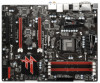
FATAL TY Z77 PERFORMANCE USB3_4_5 36 PCIE1 LAN PHY XFast LAN PCI Express 3.0 35 PCIE2 Super I/O CMOS Battery 34 PCIE3 10 Front USB 3.0 64Mb BIOS 11 Intel CLRCMOS1 1 12 Z77 1155-Pin CPU Socket 22 SATA2 Connector (SATA2_1, Black) 4 CPU Fan Connector (CPU_FAN2) 23 Dr. Debug 5 CPU - ASRock Fatal1ty Z77 Performance | User Manual - Page 16
1.4 I/O Panel 1 2 3 45 6 7 10 8 11 9 12 18 17 16 1 USB 2.0 Ports (USB01) 2 D-Sub Port (VGA1) 3 USB 3.0 Ports (USB01) 4 Fatal1ty Mouse Port (USB2) 5 USB 2.0 Port (USB3) * 6 LAN RJ-45 Port 7 Central / Bass (Orange) 8 Rear Speaker (Black) 9 Optical SPDIF Out Port 15 14 13 10 Line - ASRock Fatal1ty Z77 Performance | User Manual - Page 17
To enable Multi-Streaming function, you need to connect a front panel audio cable to the front panel audio header. After restarting your computer, you will find "Mixer" tool on your system. Please select "Mixer ToolBox" , click "Enable playback multi-streaming", and click "ok". Choose "2CH", "4CH - ASRock Fatal1ty Z77 Performance | User Manual - Page 18
Precautions Take note of the following precautions before you install motherboard components or change any motherboard settings. 1. Unplug the power cord from the wall socket before touching any components. 2. To avoid damaging the motherboard's components due to static electricity, NEVER place your - ASRock Fatal1ty Z77 Performance | User Manual - Page 19
of Intel 1155-Pin CPU, please follow the steps below. Load Plate Load Lever Contact Array Socket Body 1155-Pin Socket Overview Before you insert the 1155-Pin CPU into the socket, please check if the CPU the PnP cap. 2. This cap must be placed if returning the motherboard for after service. 19 - ASRock Fatal1ty Z77 Performance | User Manual - Page 20
key Pin1 Pin1 orientation key notch 1155-Pin CPU alignment key 1155-Pin Socket For proper inserting, please ensure to match the two orientation key notches of the CPU with the two alignment keys of the socket. Step 3-3. Carefully place the CPU into the socket by using a purely vertical motion - ASRock Fatal1ty Z77 Performance | User Manual - Page 21
fan operation or contact other components. Please be noticed that this motherboard supports Combo Cooler Option (C.C.O.), which provides flexible options to adopt three different CPU cooler types, Socket LGA 775, LGA 1155 and LGA 1156. The white throughholes are for Socket LGA 1155/1156 CPU fan. 21 - ASRock Fatal1ty Z77 Performance | User Manual - Page 22
may be damaged. 5. Some DDR3 1GB double-sided DIMMs with 16 chips may not work on this motherboard. It is not recommended to install them on this motherboard. 6. For optimal compatibility and stability while overclocking memory frequency, it is recommended to install one memory module on DDR3_B2 - ASRock Fatal1ty Z77 Performance | User Manual - Page 23
matches the break on the slot. break notch notch break The DIMM only fits in one correct orientation. It will cause permanent damage to the motherboard and the DIMM if you force the DIMM into the slot at incorrect orientation. Step 3. Firmly insert the DIMM into the slot until the retaining - ASRock Fatal1ty Z77 Performance | User Manual - Page 24
connect a chassis fan to the motherboard's chassis fan connector (CHA_FAN1 or CHA_FAN2) when using multiple graphics cards for better thermal environment. 4. Only PCIE1 slot supports Gen 3 speed. To run the PCI Express in Gen 3 speed, please install an Ivy Bridge CPU. If you install a Sandy Bridge - ASRock Fatal1ty Z77 Performance | User Manual - Page 25
Service Pack 2 / VistaTM / 7 OS. Quad CrossFireXTM is supported with Windows® VistaTM / 7 OS only. Please check AMD's website for ATITM CrossFireXTM driver updates. 1. If a customer incorrectly configures their system, they will not see the performance card manuals for detailed installation guide. - ASRock Fatal1ty Z77 Performance | User Manual - Page 26
Bridge Interconnects on the top of the Radeon graphics cards. (The CrossFire Bridge is provided with the graphics card you purchase, not bundled with this motherboard. Please refer to your graphics card vendor for details.) CrossFire Bridge or Step 3. Connect the DVI monitor cable to the DVI - ASRock Fatal1ty Z77 Performance | User Manual - Page 27
utility to uninstall any previously installed Catalyst drivers prior to installation. Please check AMD's website for ATITM driver updates. Step 3. Step 4. Step 5. Install the required drivers to your system. For Windows® XP OS: A. AMD recommends Windows® XP Service Pack 2 or higher to be installed - ASRock Fatal1ty Z77 Performance | User Manual - Page 28
identification or explanation and to the owners' benefit, without intent to infringe. * For further information of AMD CrossFireXTM technology, please check AMD's website for updates and details. 28 - ASRock Fatal1ty Z77 Performance | User Manual - Page 29
VGA cards to this motherboard. This motherboard also provides independent display controllers for DVI-D, D-Sub and HDMI to support dual VGA output so DVI-D port HDMI port 2. If you have already installed the onboard VGA driver from our support CD to your system, you can freely enjoy the benefits of - ASRock Fatal1ty Z77 Performance | User Manual - Page 30
Display Feature This motherboard supports surround display upgrade. With the internal VGA output support (DVI-D, D-Sub is inserted to this motherboard. 4. Install the onboard VGA driver and the add-on PCI Express VGA card driver to your system. If you have installed the drivers already, there is - ASRock Fatal1ty Z77 Performance | User Manual - Page 31
motherboard, you need to adopt a monitor that supports HDCP function as well. Therefore, you can enjoy the superior display quality with high-definition HDCP encryption contents. Please refer to the instructions of content as it is being transmitted. Products compatible with the HDCP scheme such as - ASRock Fatal1ty Z77 Performance | User Manual - Page 32
to clear the CMOS when you just finish updating the BIOS, you must boot up the system first, and then shut it down before you do the clear-CMOS action. Please be noted that the password, date, time, user default profile, 1394 GUID and MAC address will be cleared only if the - ASRock Fatal1ty Z77 Performance | User Manual - Page 33
Placing jumper caps over the headers and connectors will cause permanent damage of the motherboard! Serial ATA2 Connectors (SATA2_0: see p.15, No. 19) (SATA2_1: see will not function. These two Serial ATA3 (SATA3) connectors support SATA data cables for internal storage devices. The current SATA3 - ASRock Fatal1ty Z77 Performance | User Manual - Page 34
panel, there is one USB 3.0 header on this motherboard. This USB 3.0 header can support two USB 3.0 ports. Infrared Module Header (5-pin IR1 supports Jack Sensing, but the panel wire on the chassis must support HDA to function correctly. Please follow the instruction in our manual and chassis manual - ASRock Fatal1ty Z77 Performance | User Manual - Page 35
): Connect to the reset switch on the chassis front panel. Press the reset switch to restart the computer if the computer freezes and fails to perform a normal restart. PLED (System Power LED): Connect to the power status indicator on the chassis front panel. The LED is on when the system is - ASRock Fatal1ty Z77 Performance | User Manual - Page 36
CPU_FAN_SPEED 3 (see p.15, No. 5) +12V 2 GND 1 Please connect the CPU fan cable to the connector and match the black wire to the ground pin. Though this motherboard provides 4-Pin CPU fan (Quiet Fan) support, the 3-Pin CPU fan still can work successfully even without the fan speed control - ASRock Fatal1ty Z77 Performance | User Manual - Page 37
1 Please connect an ATX 12V power supply to this connector. Though this motherboard provides 8-pin ATX 12V power connector, it can still work if you 31) 4-Pin ATX 12V Power Supply Installation 4 1 This COM1 header supports a serial port module. HDMI_SPDIF Header (2-pin HDMI_SPDIF1) (see p.15 - ASRock Fatal1ty Z77 Performance | User Manual - Page 38
2.11 Smart Switches The motherboard has three smart switches: power switch, reset switch and clear CMOS switch, allowing users to quickly turn on/off or reset the sytem clear the - ASRock Fatal1ty Z77 Performance | User Manual - Page 39
. Debug is used to provide code information, which makes troubleshooting even easier. Please see the diagrams below for reading the CPU initialization is started Pre-memory CPU initialization (CPU module specific) Pre-memory CPU initialization (CPU module specific) Pre-memory CPU initialization (CPU - ASRock Fatal1ty Z77 Performance | User Manual - Page 40
memory detected Unspecified memory initialization error Memory not installed Invalid CPU type or Speed CPU mismatch CPU self test failed or possible CPU cache error CPU micro-code is not found or micro-code update is failed Internal CPU error reset PPI is not available Reserved for future AMI error - ASRock Fatal1ty Z77 Performance | User Manual - Page 41
Services CPU DXE initialization is started CPU DXE initialization (CPU module specific) CPU DXE initialization (CPU module specific) CPU DXE initialization (CPU module specific) CPU DXE initialization (CPU Device Selection (BDS) phase is started Driver connecting is started PCI Bus initialization is - ASRock Fatal1ty Z77 Performance | User Manual - Page 42
below) Ready To Boot event Legacy Boot event Exit Boot Services event Runtime Set Virtual Address MAP Begin Runtime Set Virtual Address future AMI codes OEM BDS initialization codes CPU initialization error North Bridge initialization error South update is failed Reset protocol is not available 42 - ASRock Fatal1ty Z77 Performance | User Manual - Page 43
hard disk. 2.14 Serial ATA3 (SATA3) Hard Disks Installation This motherboard adopts Intel® Z77 chipset that supports Serial ATA3 (SATA3) hard disks and RAID (RAID 0, RAID 1, RAID 5, RAID 10, Intel Rapid Storage and Intel Smart Response Technology) functions for SATA3_0 and SATA3_1 connectors. You - ASRock Fatal1ty Z77 Performance | User Manual - Page 44
This motherboard supports Hot Plug and Hot Swap functions for SATA / SATA2 in RAID / AHCI mode. Intel® Z77 chipset provides hardware support for is still power-on and in working condition. However, please note that it cannot perform Hot Plug if the OS has been installed into the SATA / SATA2 HDD. - ASRock Fatal1ty Z77 Performance | User Manual - Page 45
its limitation, the SATA / SATA2 / SATA3 Hot Plug support information of our motherboard is indicated in the product spec on our website: www.asrock.com 2. Make sure your SATA / SATA2 / SATA3 HDD can support Hot Plug function from your dealer or HDD user manual. The SATA / SATA2 / SATA3 HDD, which - ASRock Fatal1ty Z77 Performance | User Manual - Page 46
supply 1x4-pin cable. Step 2 Connect SATA data cable to the motherboard's SATA2 / SATA3 connector. SATA power cable 1x4-pin power connector of attention, before you process the Hot Unplug: Please do follow below instruction sequence to process the Hot Unplug, improper procedure will cause the SATA - ASRock Fatal1ty Z77 Performance | User Manual - Page 47
Guide and the document in the support CD, "Guide to Intel Rapid Storage", which is located in the folder at the following path: .. \ Intel Rapid Storage Information If you want to use "Intel Rapid Storage" in Windows® environment, install "SATAII driver" from the Support CD again so that "Intel - ASRock Fatal1ty Z77 Performance | User Manual - Page 48
to install Windows® XP / XP 64-bit OS on your SATA / SATA2 / SATA3 HDDs without RAID functions, please follow below steps. AHCI mode is not supported under Windows® XP / XP 64-bit. Using SATA / SATA2 / SATA3 HDDs without NCQ function STEP 1: Set Up UEFI. A. Enter UEFI SETUP UTILITY Advanced screen - ASRock Fatal1ty Z77 Performance | User Manual - Page 49
chip on the motherboard stores the UEFI SETUP UTILITY. You may run the UEFI SETUP UTILITY when you start up the computer. Please press or during the Power-On-Self-Test (POST) to enter the UEFI SETUP UTILITY, otherwise, POST will continue with its test updated, overclocking - ASRock Fatal1ty Z77 Performance | User Manual - Page 50
3.1.2 Navigation Keys Please check the following table for the function description of each navigation key. Navigation Key(s) Function Description / Moves cursor left or right to select Screens / Moves cursor up or down to select items + / - To change option for the selected items - ASRock Fatal1ty Z77 Performance | User Manual - Page 51
overclocking features. Load Optimized CPU OC Setting You can use this option to load optimized CPU overclocking setting. Please note that overclocing may cause damage to your CPU and motherboard CPU does not support Intel SpeedStep technology. Please note that enabling this function may reduce CPU - ASRock Fatal1ty Z77 Performance | User Manual - Page 52
disable GT OverClocking Support. The default value is [Disabled]. DRAM Timing Configuration Load XMP Setting Use this to load XMP setting. Configuration options: [Auto], [Default], [Profile 1] and [Profile 2]. The default value is [Auto]. DRAM Frequency If [Auto] is selected, the motherboard will detect - ASRock Fatal1ty Z77 Performance | User Manual - Page 53
setting. The default is [Auto]. DRAM tRP Use this item to change Row Precharge Time (tRP) Auto/Manual setting. The default is [Auto]. DRAM tRAS Use this item to change RAS# Active Time (tRAS) Auto/Manual setting. The default is [Auto]. Command Rate (CR) Use this item to change Command Rate (CR - ASRock Fatal1ty Z77 Performance | User Manual - Page 54
Activate Window (tFAW) Auto/Manual setting. The default is [Auto]. DRAM tCWL Use this item to change CAS# Write Latency (tCWL) Auto/Manual setting. The default is select PCH Voltage. The default value is [Auto]. CPU PLL Voltage Use this to select CPU PLL Voltage. The default value is [Auto]. VCCSA - ASRock Fatal1ty Z77 Performance | User Manual - Page 55
User Defaults In this option, you are allowed to load and save three user defaults according to your own requirements. 55 - ASRock Fatal1ty Z77 Performance | User Manual - Page 56
following items: CPU Configuration, North Bridge Configuration, South Bridge Configuration, Intel(R) Rapid Start Technology, Intel(R) Smart Connect drive, floppy disk or hard drive and launch this tool, then you can update your UEFI only in a few clicks without preparing an additional floppy diskette or - ASRock Fatal1ty Z77 Performance | User Manual - Page 57
(C1). The C1 state is supported through the native processor instructions HLT and MWAIT and requires no hardware support from the chipset. In the C1 power state, the processor maintains the context of the system caches. CPU C3 State Support Use this to enable or disable CPU C3 (ACPI C2) report to - ASRock Fatal1ty Z77 Performance | User Manual - Page 58
to execute codes. This option will be hidden if the current CPU does not support No-Excute Memory Protection. Intel Virtualization Technology When this option is set to [Enabled], a VMM (Virtual Machine Architecture) can utilize the additional hardware capabilities provided by Vanderpool Technology - ASRock Fatal1ty Z77 Performance | User Manual - Page 59
PCI Express] as the boot graphic adapter priority. The default value is [PCI Express]. VT-d Use this to enable or disable Intel® VT-d technology (Intel® Virtualization Technology for Directed I/O). The default value of this feature is [Disabled]. Share Memory This allows you to set onboard VGA share - ASRock Fatal1ty Z77 Performance | User Manual - Page 60
HDMI HD Audio feature. Onboard LAN This allows you to enable or disable the Onboard LAN feature. Deep Sleep Mobile platforms support Deep S4/S5 in DC only and desktop platforms support Deep S4/S5 in AC only. The default value is [Enabled in S5]. Restore on AC/Power Loss This allows - ASRock Fatal1ty Z77 Performance | User Manual - Page 61
3.4.4 Intel(R) Rapid Start Technology Intel(R) Rapid Start Technology Use this item to enable or disable Intel(R) Rapid Start Technology. Intel(R) Rapid Start Technology is a new zero power hibernation mode which allows users to resume in just 5-6 seconds. The default is [Disabled]. 61 - ASRock Fatal1ty Z77 Performance | User Manual - Page 62
(R) Smart Connect Technology Intel(R) Smart Connect Technology Use this item to enable or disable Intel(R) Smart Connect Technology. Intel(R) Smart Connect Technology keeps your e-mail and social networks, such as Twitter, Facebook, etc. updated automatically while the computer is in sleep mode. The - ASRock Fatal1ty Z77 Performance | User Manual - Page 63
IDE Mode], [AHCI Mode] and [RAID Mode]. The default value is [AHCI Mode]. AHCI (Advanced Host Controller Interface) supports NCQ and other new features that will improve SATA disk performance but IDE mode does not have these advantages. SATA Aggressive Link Power Management Use this item to configure - ASRock Fatal1ty Z77 Performance | User Manual - Page 64
3.4.7 Super IO Configuration Serial Port Use this item to enable or disable the onboard serial port. Serial Port Address Use this item to set the address for the onboard serial port. Configuration options: [3F8h / IRQ4] and [3E8h / IRQ4]. Infrared Port Use this item to enable or disable the onboard - ASRock Fatal1ty Z77 Performance | User Manual - Page 65
-toRAM feature. Selecting [Auto] will enable this feature if the OS supports it. Check Ready Bit Use this item to enable or disable the feature ]. Please set this option to [Enabled] if you plan to use this motherboard to submit Windows® VistaTM certification. PS/2 Keyboard Power On Use this item - ASRock Fatal1ty Z77 Performance | User Manual - Page 66
use of USB 2.0 controller. USB 3.0 Controller Use this item to enable or disable the use of USB 3.0 controller. Legacy USB Support Use this option to select legacy support for USB devices. There are four configuration options: [Enabled], [Auto], [Disabled] and [UEFI Setup Only]. The default value is - ASRock Fatal1ty Z77 Performance | User Manual - Page 67
CPU temperature, motherboard temperature, CPU fan speed, chassis fan speed, and the critical voltage. CPU Fan 1 & 2 Setting This allows you to set CPU fan set chassis fan 3's speed. Configuration options: [Full On] and [Manual]. The default value is [Full On]. Over Temperature Protection Use this to - ASRock Fatal1ty Z77 Performance | User Manual - Page 68
3.6 Boot Screen In this section, it will display the available devices on your system for you to configure the boot settings and the boot priority. Setup Prompt Timeout This shows the number of seconds to wait for setup activation key. 65535(0XFFFF) means indefinite waiting. Bootup Num-Lock If this - ASRock Fatal1ty Z77 Performance | User Manual - Page 69
3.7 Security Screen In this section, you may set or change the supervisor/user password for the system. For the user password, you may also clear it. 69 - ASRock Fatal1ty Z77 Performance | User Manual - Page 70
3.8 Exit Screen Save Changes and Exit When you select this option, the following message "Save configuration changes and exit setup?" will pop-out. Select [Yes] to save the changes and exit the UEFI SETUP UTILITY. Discard Changes and Exit When you select this option, the following message "Discard - ASRock Fatal1ty Z77 Performance | User Manual - Page 71
install the necessary drivers to activate the devices. 4.2.3 Utilities Menu The Utilities Menu shows the application softwares that the motherboard supports. Click on a specific item then follow the installation wizard to install it. 4.2.4 Contact Information If you need to contact ASRock or want to - ASRock Fatal1ty Z77 Performance | User Manual - Page 72
Installing OS on a HDD Larger Than 2TB in AHCI Mode This motherboard adopts UEFI BIOS that allows Windows® OS to be installed on a large size HDD (>2TB). Please follow the procedures below to install the operating system. 1. Please make sure - ASRock Fatal1ty Z77 Performance | User Manual - Page 73
HDD Larger Than 2TB in RAID Mode This motherboard adopts UEFI BIOS that allows Windows® OS to be installed on 2. Copy Intel® RAID drivers into a USB flash disk. You can download the driver from ASRock's website and unzip the file into a USB flash disk OR copy the file from ASRock motherboard support CD. - ASRock Fatal1ty Z77 Performance | User Manual - Page 74
Follow Windows® Installation Guide to install OS. If you install Windows® 7 64-bit / VistaTM 64-bit on a large hard disk (ex. Disk volume > 2TB), it may take more time to boot into Windows® or install driver/utilities. If you encounter this problem, you will need to follow the instructions below to - ASRock Fatal1ty Z77 Performance | User Manual - Page 75
B. Disable "Volume Shadow Copy" service. a. Type "computer management" in the Start Menu, then press "Enter". b. Go to "Services and Applications>Services"; Then double click "Volume Shadow Copy". 75 - ASRock Fatal1ty Z77 Performance | User Manual - Page 76
then Click "OK". C. Reboot your system. D. After reboot, please start to install motherboard drivers and utilities. Windows® 7 64-bit: A. Please request the hotfix KB2505454 through this link: http://support.microsoft.com/kb/2505454/ B. After installing Windows® 7 64-bit, install the hotfix kb2505454
-
 1
1 -
 2
2 -
 3
3 -
 4
4 -
 5
5 -
 6
6 -
 7
7 -
8
-
9
-
10
-
11
-
12
-
13
-
14
-
15
-
16
-
17
-
18
-
19
-
20
-
21
-
22
-
23
-
24
-
25
-
26
-
27
-
28
-
29
-
30
-
31
-
32
-
33
-
34
-
35
-
36
-
37
-
38
-
39
-
40
-
41
-
42
-
43
-
44
-
45
-
46
-
47
-
48
-
49
-
50
-
51
-
52
-
53
-
54
-
55
-
56
-
57
-
58
-
59
-
60
-
61
-
62
-
63
-
64
-
65
-
66
-
67
-
68
-
69
-
70
-
71
-
72
-
73
-
74
-
75
-
76
 |
 |

1
Fatal1ty Z77 Performance Series
User Manual
Version 1.0
Published December 2011
Copyright©2011 ASRock INC. All rights reserved.