ASRock Fatal1ty Z77 Professional Quick Installation Guide
ASRock Fatal1ty Z77 Professional Manual
 |
View all ASRock Fatal1ty Z77 Professional manuals
Add to My Manuals
Save this manual to your list of manuals |
ASRock Fatal1ty Z77 Professional manual content summary:
- ASRock Fatal1ty Z77 Professional | Quick Installation Guide - Page 1
Winter 2001 because I would be competing in a totally different first person shooter (fps) game, Alien vs. Predator II. I won that competition and walked away with a new car. The next year I won has become the figurehead for eSports worldwide". 1 Fatal1ty Z77 Professional Series Motherboard English - ASRock Fatal1ty Z77 Professional | Quick Installation Guide - Page 2
The Fatal1ty name, Fatal1ty logos and the Fatal1ty likeness are registered trademarks of Fatal1ty, Inc., and are used under license. © 2011 Fatal1ty, Inc. All rights reserved. All other trademarks are the property of their respective owners. 2 Fatal1ty Z77 Professional Series Motherboard English - ASRock Fatal1ty Z77 Professional | Quick Installation Guide - Page 3
defect or error in the manual or product. Fatal1ty, Inc., and are used under license. © 2010 Fatal1ty, Inc. All rights reserved. All other trademarks are the property of their respective owners. Fatal1ty website: www.fatal1ty.com Published December 2011 3 Fatal1ty Z77 Professional Series Motherboard - ASRock Fatal1ty Z77 Professional | Quick Installation Guide - Page 4
BIOS SPEAKER1 1 PLED1 1 PLED PWRBTN CHA_FAN3 1 HDLED RESET PANEL1 RSTBTN 16 17 18 1 2 3 4 5 6 7 8 9 10 11 12 13 14 15 16 17 18 19 20 21 22 4 32 31 30 29 28 27 26 25 24 23 22 21 20 19 1155-Pin CPU Socket 23 ATX (CHA_FAN2) Fatal1ty Z77 Professional Series Motherboard English - ASRock Fatal1ty Z77 Professional | Quick Installation Guide - Page 5
10 13 21 20 19 18 17 16 15 14 1 PS/2 Keyboard/Mouse Port (Purple/Green) ** 12 Front Speaker (Lime) 2 DisplayPort (DP1) 13 Microphone (Pink) 3 USB 2.0 Ports (USB01) 14 USB 3.0 Ports (USB3_45) * 4 LAN RJ-45 Port 15 IEEE 1394 Port 5 Fatal1ty 5 Fatal1ty Z77 Professional Series Motherboard - ASRock Fatal1ty Z77 Professional | Quick Installation Guide - Page 6
Primary output" to use Rear Speaker, Central/Bass, and Front Speaker, or select "Realtek HDA Audio 2nd output" to use front panel audio. *** eSATA3 connector supports SATA Gen3 in cable 1M. English 6 Fatal1ty Z77 Professional Series Motherboard - ASRock Fatal1ty Z77 Professional | Quick Installation Guide - Page 7
To get better performance in Windows® 7 / 7 64-bit / VistaTM / VistaTM 64bit, it is recommended to set the BIOS option in Storage Configuration to AHCI mode. For the BIOS setup, please refer to the "User Manual" in our support CD for details. 7 Fatal1ty Z77 Professional Series Motherboard English - ASRock Fatal1ty Z77 Professional | Quick Installation Guide - Page 8
which are GPU integrated. - Supports Intel® HD Graphics Built-in Visuals: Intel® Quick Sync Video, Intel® InTruTM 3D, Intel® Clear Video HD Technology, Intel® InsiderTM, Intel® HD Graphics 2500/4000, Intel® Advanced Vector Extensions (AVX) English 8 Fatal1ty Z77 Professional Series Motherboard - ASRock Fatal1ty Z77 Professional | Quick Installation Guide - Page 9
Intel® Ivy Bridge CPU. Pixel Shader 4.1, DirectX 10.1 with Intel® Sandy Bridge CPU. - Max. shared memory 1760MB (see CAUTION 5) - Dual VGA Output: support HDMI and DisplayPort ports by independent display controllers - Supports (see CAUTION 7) English 9 Fatal1ty Z77 Professional Series Motherboard - ASRock Fatal1ty Z77 Professional | Quick Installation Guide - Page 10
- 1 x Clear CMOS Switch with LED - 1 x Power Switch with LED - 1 x Reset Switch with LED - 64Mb AMI UEFI Legal BIOS with GUI support - Supports "Plug and Play" - ACPI 1.1 Compliance Wake Up Events - Supports jumperfree - SMBIOS 2.3.1 Support English 10 Fatal1ty Z77 Professional Series Motherboard - ASRock Fatal1ty Z77 Professional | Quick Installation Guide - Page 11
, CE, WHQL - ErP/EuP Ready (ErP/EuP ready power supply is required) (see CAUTION 21) * For detailed product information, please visit our website: http://www.asrock.com English 11 Fatal1ty Z77 Professional Series Motherboard - ASRock Fatal1ty Z77 Professional | Quick Installation Guide - Page 12
caused by overclocking. CAUTION! 1. About the settings of "Hyper Threading Technology", please check page 73 of the "User Manual" in the support CD. 2. This motherboard supports Dual Channel same OC settings. In Mouse Polling mode, F-Stream 12 Fatal1ty Z77 Professional Series Motherboard English - ASRock Fatal1ty Z77 Professional | Quick Installation Guide - Page 13
lower the latency in games. Traffic Shaping: You can watch Youtube HD videos and download simultaneously. Real-Time Analysis of Your Data: With the status window, you can easily recognize which data streams you are transferring currently. 13 Fatal1ty Z77 Professional Series Motherboard English - ASRock Fatal1ty Z77 Professional | Quick Installation Guide - Page 14
types, Socket LGA 775, LGA 1155 and LGA 1156. Please be noticed that not all the 775 and 1156 CPU Fan can be used. 20. ASRock XFast RAM is not supported by Microsoft® Windows® XP / XP 64-bit. Intel® Smart Connect Technology and Intel® USB 3.0 ports are not supported by Microsoft® Windows® VistaTM - ASRock Fatal1ty Z77 Professional | Quick Installation Guide - Page 15
motherboard. Before you install or remove any component, ensure that the power is switched off or the power cord is detached from the power supply. Failure to do so may cause severe damage to the motherboard, peripherals, and/or components. 15 Fatal1ty Z77 Professional Series Motherboard English - ASRock Fatal1ty Z77 Professional | Quick Installation Guide - Page 16
of Intel 1155-Pin CPU, please follow the steps below. Load Plate Load Lever Contact Array Socket Body 1155-Pin Socket Overview Before you insert the 1155-Pin CPU into the socket, cap must be placed if returning the motherboard for after service. 16 Fatal1ty Z77 Professional Series Motherboard - ASRock Fatal1ty Z77 Professional | Quick Installation Guide - Page 17
the CPU is within the socket and properly mated to the orient keys. Step 4. Close the socket: Step 4-1. Flip the load plate onto the IHS. Step 4-2. Press down the load lever, and secure it with the load plate tab under the retention tab. English 17 Fatal1ty Z77 Professional Series Motherboard - ASRock Fatal1ty Z77 Professional | Quick Installation Guide - Page 18
be noticed that this motherboard supports Combo Cooler Option (C.C.O.), which provides flexible options to adopt three different CPU cooler types, Socket LGA 775, LGA 1155 and LGA 1156. The white throughholes are for Socket LGA 1155/1156 CPU fan. 18 Fatal1ty Z77 Professional Series Motherboard - ASRock Fatal1ty Z77 Professional | Quick Installation Guide - Page 19
to install them on this motherboard. 6. For optimal compatibility and stability while overclocking memory frequency, it is recommended to install one memory module on DDR3_B2 slot or two memory modules on DDR3_A2 and DDR3_ B2 slots. 19 Fatal1ty Z77 Professional Series Motherboard English - ASRock Fatal1ty Z77 Professional | Quick Installation Guide - Page 20
damage to the motherboard and the DIMM if you force the DIMM into the slot at incorrect orientation. Step 3. Firmly insert the DIMM into the slot until the retaining clips at both ends fully snap back in place and the DIMM is properly seated. English 20 Fatal1ty Z77 Professional Series Motherboard - ASRock Fatal1ty Z77 Professional | Quick Installation Guide - Page 21
thermal environment. 5. Only PCIE2 and PCIE4 slots support Gen 3 speed. To run the PCI Express in Gen 3 speed, please install an Ivy Bridge CPU. If you install a Sandy Bridge CPU, the PCI Express will run only at PCI Express Gen 2 speed. 21 Fatal1ty Z77 Professional Series Motherboard English - ASRock Fatal1ty Z77 Professional | Quick Installation Guide - Page 22
the card before you start the installation. Step 2. Remove the system unit cover (if your motherboard is already installed in a chassis). Step 3. Remove the bracket facing the slot that you intend with screws. Step 6. Replace the system cover. 22 Fatal1ty Z77 Professional Series Motherboard English - ASRock Fatal1ty Z77 Professional | Quick Installation Guide - Page 23
Guide This motherboard supports NVIDIA® SLITM and Quad SLITM (Scalable Link Interface) technology that allows you to install up to two identical PCI Express x16 graphics cards. Currently, NVIDIA® SLITM technology supports Windows cards. 23 Fatal1ty Z77 Professional Series Motherboard English - ASRock Fatal1ty Z77 Professional | Quick Installation Guide - Page 24
. Connect a VGA cable or a DVI cable to the monitor connector or the DVI connector of the graphics card that is inserted to PCIE2 slot. 24 Fatal1ty Z77 Professional Series Motherboard English - ASRock Fatal1ty Z77 Professional | Quick Installation Guide - Page 25
SLI and PhysX configuration. In Set PhysX GPU acceleration item, please select Enabled. In Select an SLI configuration item, please select Enable SLI. And click Apply. C. Reboot your system. D. You can freely enjoy the benefit of SLITM feature. 25 Fatal1ty Z77 Professional Series Motherboard English - ASRock Fatal1ty Z77 Professional | Quick Installation Guide - Page 26
SLITM and Quad SLITM mode) A. Click the Start icon on your Windows taskbar. B. From the pop-up menu, select All Programs, and please select Enabled. In Select an SLI configuration item, please select Enable SLI. And click Apply. F. Reboot your Fatal1ty Z77 Professional Series Motherboard English - ASRock Fatal1ty Z77 Professional | Quick Installation Guide - Page 27
, please refer to AMD graphics card manuals for detailed installation guide. Step 1. Insert one Radeon graphics card into PCIE2 slot and the other Radeon graphics card to PCIE4 slot. Make sure that the cards are properly seated on the slots. 27 Fatal1ty Z77 Professional Series Motherboard English - ASRock Fatal1ty Z77 Professional | Quick Installation Guide - Page 28
(CrossFire Bridge is provided with the graphics card you purchase, not bundled with this motherboard. Please refer to your graphics card vendor for details.) CrossFire Bridge or Step 3. Connect monitor cable to the DVI to D-Sub adapter.) English 28 Fatal1ty Z77 Professional Series Motherboard - ASRock Fatal1ty Z77 Professional | Quick Installation Guide - Page 29
Bridge to connect Radeon graphics cards on PCIE4 and PCIE5 slots. (CrossFireTM Bridge is provided with the graphics card you purchase, not bundled with this motherboard. Please refer to your graphics card vendor for details.) 29 Fatal1ty Z77 Professional Series Motherboard - ASRock Fatal1ty Z77 Professional | Quick Installation Guide - Page 30
D-Sub adapter to convert the DVI connector to D-Sub interface, and then connect the D-Sub monitor cable to the DVI to D-Sub adapter.) English 30 Fatal1ty Z77 Professional Series Motherboard - ASRock Fatal1ty Z77 Professional | Quick Installation Guide - Page 31
driver updates. Step 3. Step 4. Step 5. Install the required drivers to your system. For Windows® XP OS: A. ATITM recommends Windows® XP Service Pack 2 or higher to be installed (If you have Windows® XP Service three Radeon graphics cards). English 31 Fatal1ty Z77 Professional Series Motherboard - ASRock Fatal1ty Z77 Professional | Quick Installation Guide - Page 32
identification or explanation and to the owners' benefit, without intent to infringe. * For further information of ATITM CrossFireXTM technology, please check AMD website for updates and details. 32 Fatal1ty Z77 Professional Series Motherboard English - ASRock Fatal1ty Z77 Professional | Quick Installation Guide - Page 33
system already, you can freely enjoy the benefits of dual monitor function after your system boots. If you haven't installed onboard VGA driver yet, please install onboard VGA driver from our support CD to your system and restart your computer. 33 Fatal1ty Z77 Professional Series Motherboard English - ASRock Fatal1ty Z77 Professional | Quick Installation Guide - Page 34
motherboard. 4. Install the onboard VGA driver and the add-on PCI Express VGA card driver to your system. If you have installed the drivers already, there is no need to install them again. 5. Set up a multi-monitor display. For Windows eight. 34 Fatal1ty Z77 Professional Series Motherboard English - ASRock Fatal1ty Z77 Professional | Quick Installation Guide - Page 35
For Windows® 7 / 7 64-bit / VistaTM / VistaTM 64-bit OS instructions below for more details about HDCP function. What is HDCP? HDCP stands for High-Bandwidth Digital Content Protection, a specification developed by Intel purchase is compatible. 35 Fatal1ty Z77 Professional Series Motherboard English - ASRock Fatal1ty Z77 Professional | Quick Installation Guide - Page 36
10 you update the BIOS. If you need to clear the CMOS when you just finish updating the BIOS, you GUID and MAC address will be cleared only if the CMOS battery is removed. The Clear CMOS Switch has the same function as the Clear CMOS jumper. English 36 Fatal1ty Z77 Professional Series Motherboard - ASRock Fatal1ty Z77 Professional | Quick Installation Guide - Page 37
support SATA data cables for internal storage devices. The current SATA3 SATA3_A2 interface allows up to 6.0 Gb/s data transfer rate. If the eSATA3 port on the rear I/O has been SATA3_1 connected, the internal SATA3_A4 will not function. English 37 Fatal1ty Z77 Professional Series Motherboard - ASRock Fatal1ty Z77 Professional | Quick Installation Guide - Page 38
USB 2.0 ports on the I/O panel, there are two USB 2.0 headers on this motherboard. Each USB 2.0 header can support two USB 2.0 ports. Besides six default USB 3.0 ports on the I/O panel, there CD1 a CD-ROM, DVD-ROM, TV tuner card, or MPEG card. 38 Fatal1ty Z77 Professional Series Motherboard - ASRock Fatal1ty Z77 Professional | Quick Installation Guide - Page 39
supports Jack Sensing, but the panel wire on the chassis must support HDA to function correctly. Please follow the instruction in our manual and chassis manual Windows® XP / XP 64-bit OS: Select "Mixer". Select "Recorder". Then click "FrontMic". For Windows Fatal1ty Z77 Professional Series Motherboard - ASRock Fatal1ty Z77 Professional | Quick Installation Guide - Page 40
Please connect the fan cables to the fan connectors and match the black wire to the ground pin. CHA_FAN1, CHA_FAN2 and CHA_FAN3 support Fan Control. Please connect the CPU fan cable to the connector and match the black wire to the ground pin. English 40 Fatal1ty Z77 Professional Series Motherboard - ASRock Fatal1ty Z77 Professional | Quick Installation Guide - Page 41
ATX power supply. To use the 20-pin ATX power supply, please plug your power supply along with Pin 1 and Pin 13. 20-Pin ATX Power Supply Installation 1 13 ATX on this motherboard. This IEEE 1394 header can support one IEEE 1394 port. 41 Fatal1ty Z77 Professional Series Motherboard English - ASRock Fatal1ty Z77 Professional | Quick Installation Guide - Page 42
Serial port Header (9-pin COM1) (see p.4, No. 31) This COM1 header supports a serial port module. HDMI_SPDIF Header (2-pin HDMI_SPDIF1) (see p.4, No. 33) 1 GND SPDIFOUT connect the HDMI_SPDIF connector of HDMI VGA card to this header. English 42 Fatal1ty Z77 Professional Series Motherboard - ASRock Fatal1ty Z77 Professional | Quick Installation Guide - Page 43
Step 6 The Front USB 3.0 Panel is ready to use. header (USB3_6_7) on the motherboard. English The Installation Guide of Rear USB 3.0 Bracket Step 1 Unscrew the two screws from the Front USB 3.0 Step 4 Put the rear USB 3.0 bracket into the chassis. 43 Fatal1ty Z77 Professional Series Motherboard - ASRock Fatal1ty Z77 Professional | Quick Installation Guide - Page 44
2.12 Smart Switches The motherboard has three smart switches: power switch, reset switch and clear CMOS switch, allowing users to quickly No. 18) clr CMOS Clear CMOS Switch is a smart switch, allowing users to quickly clear the CMOS values. English 44 Fatal1ty Z77 Professional Series Motherboard - ASRock Fatal1ty Z77 Professional | Quick Installation Guide - Page 45
used to provide code information, which makes troubleshooting even easier. Please see the diagrams below for reading the Dr. Debug codes. Status Code 0x00 0x01 0x02 Reserved for future AMI SEC error codes Microcode not found Microcode not 45 Fatal1ty Z77 Professional Series Motherboard English - ASRock Fatal1ty Z77 Professional | Quick Installation Guide - Page 46
is found Recovery firmware image is loaded Reserved for future AMI progress codes Recovery PPI is not available Recovery capsule is not found Invalid recovery capsule Reserved for future AMI error codes DXE Core is started NVRAM initialization English 46 Fatal1ty Z77 Professional Series Motherboard - ASRock Fatal1ty Z77 Professional | Quick Installation Guide - Page 47
South Bridge Runtime Services CPU DXE codes OEM DXE initialization codes Boot Device Selection (BDS) phase is started Driver codes IDE initialization is started IDE Reset IDE Detect IDE Enable SCSI initialization is started SCSI Reset English 47 Fatal1ty Z77 Professional Series Motherboard - ASRock Fatal1ty Z77 Professional | Quick Installation Guide - Page 48
Console Output Devices are found No Console Input Devices are found Invalid password Error loading Boot Option (LoadImage returned error) Boot Option is failed (StartImage returned error) Flash update is failed Reset protocol is not available English 48 Fatal1ty Z77 Professional Series Motherboard - ASRock Fatal1ty Z77 Professional | Quick Installation Guide - Page 49
refer to the document at the following path in the Support CD for detailed procedures: ..\ RAID Installation Guide 2.16 Installing Windows® 7 / 7 64-bit / VistaTM / VistaTM 64 ports. STEP 2: Install Windows® XP / XP 64-bit OS on your system. 49 Fatal1ty Z77 Professional Series Motherboard English - ASRock Fatal1ty Z77 Professional | Quick Installation Guide - Page 50
option "ASMedia SATA3 Mode" to [IDE] for SATA3_A1 to SATA2_A4 ports. STEP 2: Install Windows® XP / XP 64-bit OS on your system. Using SATA / SATA2 / SATA3 HDDs with ports. STEP 2: Install Windows® XP / XP 64-bit OS on your system. 50 Fatal1ty Z77 Professional Series Motherboard English - ASRock Fatal1ty Z77 Professional | Quick Installation Guide - Page 51
Install Teaming driver from the following path of motherboard Support CD: 32-bit: .. \Drivers\LAN\Broadcom\Teaming\IA32 64-bit: .. \Drivers\LAN\Broadcom\Teaming\x64 (This is a special driver for , click Default to Expert Mode on next start. 51 Fatal1ty Z77 Professional Series Motherboard English - ASRock Fatal1ty Z77 Professional | Quick Installation Guide - Page 52
where its driver is disabled may negatively affect the offloading capabilities of the team. This may have an impact on the team's performance. Therefore, it is recommended that only driver-enabled network adapters be added as members to a team. 52 Fatal1ty Z77 Professional Series Motherboard English - ASRock Fatal1ty Z77 Professional | Quick Installation Guide - Page 53
10 Teams window. 13 once, an error message is virtual team adapter driver is created for supported for testing, it is recommended to connect team members to a switch. * Not all network adapters made by others are supported or fully certified for teaming. 53 Fatal1ty Z77 Professional Series Motherboard - ASRock Fatal1ty Z77 Professional | Quick Installation Guide - Page 54
click Properties. d. Configure the IP address and any other necessary TCP/IP configuration for the team, and then click OK when finished. 54 Fatal1ty Z77 Professional Series Motherboard English - ASRock Fatal1ty Z77 Professional | Quick Installation Guide - Page 55
about BIOS Setup, please refer to the User Manual (PDF file) contained in the Support CD. 4. Software Support CD information This motherboard supports various Microsoft® Windows® from the BIN folder in the Support CD to display the menus. 55 Fatal1ty Z77 Professional Series Motherboard English - ASRock Fatal1ty Z77 Professional | Quick Installation Guide - Page 56
Webseite: www.asrock.com/support/index.asp 1.1 Kartoninhalt ASRock Fatal1ty Z77 Professional Series Motherboard (ATX-Formfaktor: 30.5 cm x 24.4 cm; 12.0 Zoll x 9.6 Zoll) ASRock Fatal1ty Z77 Professional Series Schnellinstallationsanleitung ASRock Fatal1ty Z77 Professional Series Support-CD Sechs - ASRock Fatal1ty Z77 Professional | Quick Installation Guide - Page 57
unterstützt werden. - Unterstützt hochauflösende integrierte Intel®-Grafiklösungen: Intel® Quick-Sync-Video, Intel® InTruTM 3D, Intel® Clear- Video-Technik (HD), Intel® HD Graphics 2500/4000, Intel® Advanced Vector Extensions (AVX) 57 Fatal1ty Z77 Professional Series Motherboard Deutsch - ASRock Fatal1ty Z77 Professional | Quick Installation Guide - Page 58
5 x Standard-USB 2.0-Anschlüsse - 1 x Fatal1ty Mausanschluss (USB 2.0) - 1 x eSATA3-Anschluss - 6 x Standard-USB 3.0-Anschlüsse - 2 x RJ-45 LAN Port mit LED (ACT/LINK LED und SPEED LED) - 1 x IEEE 1394 Port - 1 x CMOS löschen-Schalter mit LED Deutsch 58 Fatal1ty Z77 Professional Series Motherboard - ASRock Fatal1ty Z77 Professional | Quick Installation Guide - Page 59
durch Intel® Z77, unterstützt RAID- (RAID 0, RAID 1, RAID 5, RAID 10, Intel Rapid Storage und Intel lüfter-Anschluss - 24-pin ATX-Netz-Header - 8-pin anschluss für 12V-ATX-Netzteil - Interne Audio-Anschlüsse 1 x Rücksetzschalter (Reset) mit LED 59 Fatal1ty Z77 Professional Series Motherboard - ASRock Fatal1ty Z77 Professional | Quick Installation Guide - Page 60
) - Mehrstufige Geschwindigkeitssteuerung für CPU/Gehäuse lüfter - Spannungsüberwachung: +12V, +5V, +3.3V, Vcore - Unterstützt Microsoft® Windows® 7 / 7 64-Bit / VistaTM / VistaTM 64-Bit / XP / XP 64-Bit (siehe VORSICHT 20) - FCC, CE, WHQL Deutsch 60 Fatal1ty Z77 Professional Series Motherboard - ASRock Fatal1ty Z77 Professional | Quick Installation Guide - Page 61
Der Mikrofoneingang dieses Motherboards unterstützt Stereo- und MonoModi. Der Audioausgang dieses Motherboards unterstützt 2-Kanal-, 4-Kanal-, 6-Kanal- und 8-Kanal-Modi. Stellen Sie die richtige Verbindung anhand der Tabelle auf Seite 5 her. 61 Fatal1ty Z77 Professional Series Motherboard Deutsch - ASRock Fatal1ty Z77 Professional | Quick Installation Guide - Page 62
in Echtzeit miteinander kombiniert: In einer speziellen Ansicht, die das Internet noch angenehmer und aufregender macht. ASRock-Motherboards werden exklusiv mit der SmartView-Software geliefert, die auch dafür sorgt, dass Sie immer mit 62 Fatal1ty Z77 Professional Series Motherboard Deutsch - ASRock Fatal1ty Z77 Professional | Quick Installation Guide - Page 63
der CPU-Lüfter am Motherboard richtig funktioniert, und stecken Sie bitte den Stromkabelstecker aus und dann wieder ein. Um die Wärmeableitung zu verbessern, bitte nicht vergessen, etwas Wärmeleitpaste zwischen CPU und Kühlkörper zu sprühen. 63 Fatal1ty Z77 Professional Series Motherboard Deutsch - ASRock Fatal1ty Z77 Professional | Quick Installation Guide - Page 64
verschiedenen CPU-Kühlertypen, Socket LGA 775, LGA 1155 und LGA 1156. Beachten Sie bitte, dass nicht alle 775 und 1156 CPU-Lüfter verwendet werden können. 20. ASRock XFast RAM wird von Microsoft® Windows® XP / XP 64 Bit nicht unterstützt. Intel® Smart Connect-Technologie und Intel® USB 3.0-Ports - ASRock Fatal1ty Z77 Professional | Quick Installation Guide - Page 65
der BIOS-Aktualisierung löschen. Wenn Sie das CMOS nach Abschluss der BIOS- GUID und MAC-Adresse nur gelöscht werden, wenn die CMOS-Batterie entfernt wird. Der CMOS löschen-Schalter hat dieselbe Funktion wie der CMOS löschen-Jumper. Deutsch 65 Fatal1ty Z77 Professional Series Motherboard - ASRock Fatal1ty Z77 Professional | Quick Installation Guide - Page 66
schwarz) (39-pin IDE1, siehe S.4 - No. 8) Blauer Anschluss Schwarzer Anschluss zum Motherboard zur Festplatte 80-adriges ATA 66/100/133 Kabel Hinweis: Details entnehmen Sie bitte den eine Datenübertragungsrate bis 6,0 Gb/s. Wenn Sie die 66 Fatal1ty Z77 Professional Series Motherboard Deutsch - ASRock Fatal1ty Z77 Professional | Quick Installation Guide - Page 67
Ports an den I/O-Anschlüssen befinden sich zwei USB 2.0- Anschlussleisten am Motherboard. Pro USB 2.0Anschlussleiste werden zwei USB 2.0-Ports unterstützt. USB 3.0-Header Motherboard. Dieser USB 3.0Header kann zwei USB 3.0Ports unterstützen. Deutsch 67 Fatal1ty Z77 Professional Series Motherboard - ASRock Fatal1ty Z77 Professional | Quick Installation Guide - Page 68
angeschlossen werden. E. So aktivieren Sie das Mikrofon an der Vorderseite. Bei den Betriebssystemen Windows® XP / XP 64 Bit: Wählen Sie „Mixer". Wählen Sie „Recorder" ) Dieser Header unterstützt mehrere Funktion der Systemvorderseite. Deutsch 68 Fatal1ty Z77 Professional Series Motherboard - ASRock Fatal1ty Z77 Professional | Quick Installation Guide - Page 69
Kabel- und Pinbelegung korrekt übereinstimmen. Gehäuselautsprecher-Header (4-pin SPEAKER1) (siehe S.4 - No. 20) Schließen Sie den Gehäuselautsprecher an diesen Header an. Deutsch 69 Fatal1ty Z77 Professional Series Motherboard - ASRock Fatal1ty Z77 Professional | Quick Installation Guide - Page 70
den CPU-Lüferanschluss dieses Motherboards anschließen möchten, verbinden Sie ihn bitte mit den Pins 1 - 3. Pins 1-3 anschließen Lüfter mit dreipoligem Anschluss installieren (3-pin CPU_FAN2) (sieche S.4 - No. 4) GND +12V CPU_FAN_SPEED Deutsch 70 Fatal1ty Z77 Professional Series Motherboard - ASRock Fatal1ty Z77 Professional | Quick Installation Guide - Page 71
8 5 IEEE-1394 Header (9-pin FRONT_1394) (siehe S.4 - No. 28) Installation der 4-Pin ATX 12V Energieversorgung 4 1 RXTPAM_0 GND RXTPBM_0 +12V GND 1 +12V RXTPBP_0 GND RXTPAP_0 Außer einem Header kann einen IEEE-1394 Port unterstützen. Deutsch 71 Fatal1ty Z77 Professional Series Motherboard - ASRock Fatal1ty Z77 Professional | Quick Installation Guide - Page 72
wie Fernsehgeräten, Projektoren, LCD-Geräten an das System. Bitte verbinden Sie den HDMI_SPDIF-Anschluss der HDMI-VGA-Karte mit diesem Anschluss. Deutsch 72 Fatal1ty Z77 Professional Series Motherboard - ASRock Fatal1ty Z77 Professional | Quick Installation Guide - Page 73
der Rückwand Schritt 1 Lösen Sie die beiden Schrauben am USB 3.0-Panel. Schritt 2 Schließen Sie das USB 3.0-Kabel an das USB 3.0-Blech an. Deutsch 73 Fatal1ty Z77 Professional Series Motherboard - ASRock Fatal1ty Z77 Professional | Quick Installation Guide - Page 74
USB 3.0-Blech an der Rückwand des Gehäuses ein. 1.5 Schnellschalter Dieses Motherboard besitzt drei Schnellschalter: Netzschalter, Rücksetzschalter (Reset) und CMOS löschen-Schalter, , mit dem Benutzer die CMOS-Werte schnell löschen können. Deutsch 74 Fatal1ty Z77 Professional Series Motherboard - ASRock Fatal1ty Z77 Professional | Quick Installation Guide - Page 75
der Support-CD, um die Menüs aufzurufen. Das Setup-Programm soll es Ihnen so leicht wie möglich machen. Es ist menügesteuert, d.h. Sie können in den verschiedenen Untermenüs Ihre Auswahl treffen und die Programme werden dann automatisch installiert. 75 Fatal1ty Z77 Professional Series Motherboard - ASRock Fatal1ty Z77 Professional | Quick Installation Guide - Page 76
sous Windows® 7 / 7 64 bits / VistaTM / VistaTM 64 bits, il est recommandé de paramétrer l'option BIOS dans Configuration de stockage en mode AHCI. Pour plus de détails sur l'installation BIOS, référez-vous au "Mode d'emploi" sur votre CD de support. 76 Fatal1ty Z77 Professional Series Motherboard - ASRock Fatal1ty Z77 Professional | Quick Installation Guide - Page 77
Express 2.0 x1 - 2 x slots PCI - Prend en charge AMD Quad CrossFireXTM, 3-Way CrossFireXTM et CrossFireXTM - Prend en charge NVIDIA® Quad SLITM et SLITM Français 77 Fatal1ty Z77 Professional Series Motherboard - ASRock Fatal1ty Z77 Professional | Quick Installation Guide - Page 78
cacité énergétique) 802.3az Français - Prend en charge le Dual LAN avec la fonction Teaming (pairage) - Supporte PXE Panneau arrière I/O Panel - 1 x port clavier/souris PS/2 - 1 x port HDMI - 1 x DisplayPort - 1 x port de sortie optique SPDIF 78 Fatal1ty Z77 Professional Series Motherboard - ASRock Fatal1ty Z77 Professional | Quick Installation Guide - Page 79
Intel® Z77, prend en charge USB 1.0/2.0/3.0 jusqu'à 5 Gb/s - 4 x connecteurs SATA2, prennent en charge un taux de transfert de données pouvant aller jusqu'à 3.0Go/s, supporte RAID (RAID 0, RAID 1, RAID 5, RAID 10, Intel Rapid Storage et Intel Français 79 Fatal1ty Z77 Professional Series Motherboard - ASRock Fatal1ty Z77 Professional | Quick Installation Guide - Page 80
par les processeurs à GPU intégré. - L'accélérateur hybride: - Contrôle direct de la fréquence CPU (voir ATTENTION 17) - ASRock U-COP (voir ATTENTION 18) - Garde d'échec au démarrage (B.F.G.) - Combo Cooler Option (C.C.O.) (voir ATTENTION 19) 80 Fatal1ty Z77 Professional Series Motherboard - ASRock Fatal1ty Z77 Professional | Quick Installation Guide - Page 81
+3.3V, Vcore OS - Microsoft® Windows® 7 / 7 64-bit / VistaTM overclocking, y compris ajuster les réglages du BIOS, appliquer la technologie Untied Overclocking, ou utiliser des outils de tiers pour l'overclocking. L'overclocking supporte la le guide d' Fatal1ty Z77 Professional Series Motherboard - ASRock Fatal1ty Z77 Professional | Quick Installation Guide - Page 82
et est sujet de changer. Veuillez verifier la Intel® website pour les informations recentes SVP. 6. xvYCC et Deep Color ne sont pris en charge que sous Windows® 7 64bit / 7. Le mode Deep Color ne (S4) ou hors tension (S5). Lorsque le pilote du 82 Fatal1ty Z77 Professional Series Motherboard Français - ASRock Fatal1ty Z77 Professional | Quick Installation Guide - Page 83
du système d'exploitation Windows OS 32-bit ne peuvent pas utiliser. ASRock XFast RAM diminue le temps leur durée de vie utile. 15. ASRock Crashless BIOS permet aux utilisateurs de mettre à jour leur BIOS sans qu'ils aient à craindre un plantage Fatal1ty Z77 Professional Series Motherboard Français - ASRock Fatal1ty Z77 Professional | Quick Installation Guide - Page 84
sde CPU, les sockets LGA 775, LGA 1155 et LGA 1156. Veuillez noter que tous les ventilateurs de CPU 775 et 1156 ne peuvent pas être utilisés. 20. ASRock XFast RAM n'est pas pris en charge par Microsoft® Windows® XP / XP 64-bit. Les technologie Intel® Smart Connect et ports Intel® USB 3.0 n'est pas - ASRock Fatal1ty Z77 Professional | Quick Installation Guide - Page 85
BIOS. Si vous avez besoin d'effacer le CMOS après avoir mis à jour le BIOS GUID et l'adresse MAC seront effacés seulement si la batterie du CMOS est enlevée. Le commutateur Effacer CMOS présente la même fonction que le cavalier Effacer CMOS. Français 85 Fatal1ty Z77 Professional Series Motherboard - ASRock Fatal1ty Z77 Professional | Quick Installation Guide - Page 86
vers le disque dur Câble ATA 66/100/133 80 conducteurs Note: Veuillez vous reporter aux instructions du fabricant de votre IDE périphérique pour les détails. Connecteurs Série ATA2 (SATA2_2_3: Si vous installez le disque dur sur le 86 Fatal1ty Z77 Professional Series Motherboard Français - ASRock Fatal1ty Z77 Professional | Quick Installation Guide - Page 87
défaut sur le panneau E/S, il y a une barrette USB 3.0 sur la carte mère. Cette barrette USB 3.0 peut prendre en charge deux ports USB 3.0. Français 87 Fatal1ty Z77 Professional Series Motherboard - ASRock Fatal1ty Z77 Professional | Quick Installation Guide - Page 88
CD-L GND GND CD-R CD1 Cet en-tête supporte un module infrarouge optionnel de transfert et de ré fonctionner correctement. Veuillez suivre les instructions dans notre manuel et le manuel activer le micro avant. Pour les systèmes d'exploitation Windows® XP / Fatal1ty Z77 Professional Series Motherboard - ASRock Fatal1ty Z77 Professional | Quick Installation Guide - Page 89
. Il LED è acceso quando il sistema è in funzione. Il LED continua a lampeggiare in stato S1/S3. Il LED è spento in stato S4 o S5 (spegnimento). 89 Fatal1ty Z77 Professional Series Motherboard - ASRock Fatal1ty Z77 Professional | Quick Installation Guide - Page 90
carte mère offre un support de (Ventilateur silencieux ATX 20 broches. Pour utiliser une alimentation ATX 20 broches, branchez à l'alimentation électrique ainsi qu'aux broches 1 et 13. 20-Installation de l'alimentation électrique ATX 1 13 90 Fatal1ty Z77 Professional Series Motherboard - ASRock Fatal1ty Z77 Professional | Quick Installation Guide - Page 91
ATX 12V, il peut toujours travailler si vous adoptez une approche traditionnelle à 4 broches ATX 12V alimentation. 8 5 Pour utiliser l'alimentation des 4 broches ATX carte mere. Le header de IEEE 1394 peut supporter un port de IEEE 1394. En-tête de Fatal1ty Z77 Professional Series Motherboard - ASRock Fatal1ty Z77 Professional | Quick Installation Guide - Page 92
Etape 6 Le panneau USB 3.0 frontal peut maintenant être utilisé. Le Guide d'installation du Support arrière USB 3.0 Étape 1 Dévissez les deux vis du panneau avant USB 3.0. Étape 2 Assemblez le câble USB 3.0 et le support arrière USB 3.0. Français 92 Fatal1ty Z77 Professional Series Motherboard - ASRock Fatal1ty Z77 Professional | Quick Installation Guide - Page 93
Étape 3 Vissez les deux vis dans le support arrière USB 3.0. Étape 4 Placez le support arrière USB 3.0 dans le châssis. 1.5 Interrupteur rapides Cette carte mère dispose qui permet à l'utilisateur d'effacer rapidement les valeurs du CMOS. Français 93 Fatal1ty Z77 Professional Series Motherboard - ASRock Fatal1ty Z77 Professional | Quick Installation Guide - Page 94
le BIOS, veuillez consulter le Guide de l'utilisateur (fichier PDF) dans le CD technique. 3. Informations sur le CD de support Cette carte mère supporte divers systèmes d'exploitation Microsoft® Windows®: dessus pour afficher les menus. 94 Fatal1ty Z77 Professional Series Motherboard Français - ASRock Fatal1ty Z77 Professional | Quick Installation Guide - Page 95
64-bit, si consiglia di impostare l'opzione BIOS in Storage Configuration (Configurazione di archiviazione) sulla modalità AHCI. Per l'impostazione BIOS, fare riferimento a "User Manual" (Manuale dell'utente) nel CD di supporto per dettagli. 95 Fatal1ty Z77 Professional Series Motherboard Italiano - ASRock Fatal1ty Z77 Professional | Quick Installation Guide - Page 96
con processori dotati di GPU integrata. - Supporta Intel® HD Graphics Built-in Visuals: Intel® Quick Sync Video, Intel® InTruTM 3D, Intel® Clear Video HD Technology, Intel® HD Graphics 2500/4000, Intel® Advanced Vector Extensions (AVX) 96 Fatal1ty Z77 Professional Series Motherboard Italiano - ASRock Fatal1ty Z77 Professional | Quick Installation Guide - Page 97
- Pixel Shader 5.0, DirectX 11 con CPU Intel® Ivy Bridge, Pixel Shader 4.1, DirectX 10.1 con CPU Intel® Sandy Bridge - Memoria massima condivisa 1760MB (vedi / cassa centrale / bassi / ingresso linea / cassa frontale / microfono (vedi ATTENZIONE 7) 97 Fatal1ty Z77 Professional Series Motherboard - ASRock Fatal1ty Z77 Professional | Quick Installation Guide - Page 98
di alimentazione con LED - 1 x interruttore di reset con LED - 64Mb AMI UEFI Legal BIOS con interfaccia di supporto - Supporta "Plug and Play" - Compatibile con ACPI 1.1 wake up events - Supporta jumperfree - Supporta SMBIOS 2.3.1 Italiano 98 Fatal1ty Z77 Professional Series Motherboard - ASRock Fatal1ty Z77 Professional | Quick Installation Guide - Page 99
ASRock APP Charger (vedi ATTENZIONE 10) - ASrock SmartView (vedi ATTENZIONE 11) - ASRock XFast USB (vedi ATTENZIONE 12) - ASRock XFast LAN (vedi ATTENZIONE 13) - ASRock XFast RAM (vedi ATTENZIONE 14) - ASRock Crashless BIOS .asrock.com Italiano 99 Fatal1ty Z77 Professional Series Motherboard - ASRock Fatal1ty Z77 Professional | Quick Installation Guide - Page 100
di eseguire l'overclocking della frequenza della CPU per ottenere le prestazioni ottimali del sistema. OC DNA permette di salvare le impostazioni OC come un profilo da condividere con gli amici! Gli amici possono scaricare il profilo OC sul Fatal1ty Z77 Professional Series Motherboard Italiano - ASRock Fatal1ty Z77 Professional | Quick Installation Guide - Page 101
10. Se vuoi un modo rapido e indipendente per caricare i dispositivi Apple, come iPhone/iPad/iPod Touch, ASRock ha preparato una soluzione meravigliosa: ASRock APP Charger. Basta installare il driver dati si stanno trasferendo in streaming. 101 Fatal1ty Z77 Professional Series Motherboard Italiano - ASRock Fatal1ty Z77 Professional | Quick Installation Guide - Page 102
Socket LGA 775, LGA 1155 e LGA 1156. Notare che non possono essere usate tutte le ventole CPU 775 e 1156. 20. ASRock XFast RAM non è supportato da Microsoft® Windows® XP / XP 64-bit. Tecnologia Intel® Smart Connect e porte Intel dettagli con il produttore. Fatal1ty Z77 Professional Series Motherboard - ASRock Fatal1ty Z77 Professional | Quick Installation Guide - Page 103
CMOS. Notare che password, data, ore, profilo utente predefinito, 1394 GUID e indirizzo MAC saranno cancellati solo se è rimossa la batteria della CMOS. L'interruttore Clear CMOS (Cancella CMOS) ha la stessa funzione del jumper Clear CMOS. Italiano 103 Fatal1ty Z77 Professional Series Motherboard - ASRock Fatal1ty Z77 Professional | Quick Installation Guide - Page 104
di immagazzinamento interni. SATA3_A2 L'interfaccia SATA3 attuale permette velocità di trasferimento dati fino a 6.0 SATA3_1 Gb/s. Se si installa l'HD sulla porta eSATA3 con la 104 Fatal1ty Z77 Professional Series Motherboard Italiano - ASRock Fatal1ty Z77 Professional | Quick Installation Guide - Page 105
infrarossi (5-pin IR1) IRTX +5VSB DUMMY Questo collettore supporta moduli ad infrarossi optional per (vedi p.4 Nr. 29) 1 GND IRRX la trasmissione e la ricezione senza fili. Fatal1ty Z77 Professional Series Motherboard 105 - ASRock Fatal1ty Z77 Professional | Quick Installation Guide - Page 106
in modo corretto. Attenersi alle istruzioni del nostro manuale e del manuale del telaio per installare il sistema. 2. Se si AC'97. E. Per attivare il microfono frontale. Sistema operativo Windows® XP / XP 64-bit: Selezionare "Mixer". Selezionare " cavi. Fatal1ty Z77 Professional Series Motherboard - ASRock Fatal1ty Z77 Professional | Quick Installation Guide - Page 107
+12V CHA_FAN_SPEED facendo combaciare il cavo nero col pin di terra. (3-pin CHA_FAN2) CHA_FAN1, CHA_FAN2 e (vedi p.4 Nr. 43) CHA_FAN3 supportano la funzione Fan Control. 107 Fatal1ty Z77 Professional Series Motherboard Italiano - ASRock Fatal1ty Z77 Professional | Quick Installation Guide - Page 108
ATX a 20 pin, collegare l'alimentatore con il Pin 1 e il Pin 13. Installazione dell'alimentatore ATX a 20 pin 1 13 Connettore ATX 12 V (8-pin ATX12V1) (vedi p.4 Nr. 2) 8 5 4 1 Collegare un alimentatore ATX 12 V a questo connettore. Italiano 108 Fatal1ty Z77 Professional Series Motherboard - ASRock Fatal1ty Z77 Professional | Quick Installation Guide - Page 109
Nr. 28) Collettore porta COM (9-pin COM1) (vedi p.4 Nr. 31) Installazione elettrica 4-Pin ATX 12V 4 1 RXTPAM_0 GND RXTPBM_0 +12V GND 1 +12V RXTPBP_0 GND RXTPAP_0 Accanto alla porta di HDMI_SPDIF della scheda VGA HDMI a questo header. Italiano 109 Fatal1ty Z77 Professional Series Motherboard - ASRock Fatal1ty Z77 Professional | Quick Installation Guide - Page 110
il cavo USB 3.0 e il supporto USB 3.0 posteriore. Punto 3 Avvitare le due viti nel supporto USB 3.0 Punto 4 Inserire il supporto USB 3.0 posteriore. posteriore nel telaio. 110 Fatal1ty Z77 Professional Series Motherboard - ASRock Fatal1ty Z77 Professional | Quick Installation Guide - Page 111
agli utenti di resettare rapidamente il sistema. L'interruttore di pulizia CMOS è un interruttore rapido che consente agli utenti di cancellare velocemente i valori CMOS. Italiano 111 Fatal1ty Z77 Professional Series Motherboard - ASRock Fatal1ty Z77 Professional | Quick Installation Guide - Page 112
BIOS, fare riferimento al Manuale dell'Utente (PDF file) contenuto nel cd di supporto. 3. Software di supporto e informazioni su CD Questa scheda madre supporta vari sistemi operativi Microsoft® Windows due volte per visualizzare i menù. 112 Fatal1ty Z77 Professional Series Motherboard Italiano - ASRock Fatal1ty Z77 Professional | Quick Installation Guide - Page 113
64 bits, es recomendable establecer la opción del BIOS de la configuración de almacenamiento en el modo AHCI. Para obtener detalles sobre la configuración del BIOS, consulte el "Manual del usuario" que se encuentra en nuestro CD de soporte. 113 Fatal1ty Z77 Professional Series Motherboard Español - ASRock Fatal1ty Z77 Professional | Quick Installation Guide - Page 114
VGA sólo se soportan con procesadores con GPU integrada. - Admite Intel® HD Graphics Built-in Visuals: Intel® Quick Sync Video, Intel® InTruTM 3D, Intel® Clear Video HD Technology, Intel® HD Graphics 2500/4000 e Intel® Advanced Vector 114 Fatal1ty Z77 Professional Series Motherboard Español - ASRock Fatal1ty Z77 Professional | Quick Installation Guide - Page 115
de ratón Fatal1ty (USB 2.0) - 1 x Conector eSATA3 - 6 x puertos USB 3.0 predeterminados - 2 x puertos LAN RJ-45 con LED (LED de ACCIÓN/ENLACE y LED de VELOCIDAD) - 1 x puerto IEEE 1394 - 1 x conmutador de borrado de memoria CMOS con Español 115 Fatal1ty Z77 Professional Series Motherboard - ASRock Fatal1ty Z77 Professional | Quick Installation Guide - Page 116
conectores SATA3 de 6,0 Gb/s con chip Intel® Z77 con funciones RAID (RAID 0, RAID 1, RAID 5, RAID 10, Intel Rapid Storage y tecnología Intel Smart Response), NCQ, AHCI y de Hot USB 3.0 adicionales) - 1 x Dr. Debug (indicador LED de avería de 7 segmentos) Fatal1ty Z77 Professional Series Motherboard - ASRock Fatal1ty Z77 Professional | Quick Installation Guide - Page 117
silencioso del procesador y el chasis (ajuste automático de la velocidad del ventilador del chasis en función de la temperatura del procesador) Español 117 Fatal1ty Z77 Professional Series Motherboard - ASRock Fatal1ty Z77 Professional | Quick Installation Guide - Page 118
el ajuste del BIOS, aplicando la consulte página 73 del Manual del Usuario en el Windows® 7 de 64 bits/ 7. El modo Deep Color solamente se habilitará si la pantalla admite 12 bpc en EDID. HBR se admite en Windows® 7 64 bits / 7 / VistaTM 64 bits / VistaTM. Fatal1ty Z77 Professional Series Motherboard - ASRock Fatal1ty Z77 Professional | Quick Installation Guide - Page 119
actualización de BIOS le permitirá actualizar el BIOS del sistema sin necesidad de acceder a ningún sistema operativo, como MS-DOS o Windows®. Gracias a sin precedentes. Sitio web de ASRock: http://www.asrock.com/Feature/AppCharger/index. asp Fatal1ty Z77 Professional Series Motherboard 119 Español - ASRock Fatal1ty Z77 Professional | Quick Installation Guide - Page 120
utilizar con procesadores de 32 bits en sistemas operativos Windows®. ASRock XFast RAM acorta el tiempo de carga de los suministro de energía durante el proceso de actualización del BIOS, ASRock Crashless BIOS finalizará de manera automática el proceso de Fatal1ty Z77 Professional Series Motherboard - ASRock Fatal1ty Z77 Professional | Quick Installation Guide - Page 121
una fuente de alimentación que cumpla la directiva EuP, le recomendamos que consulte con el fabricante de la fuente de alimentación para obtener más detalles. 121 Fatal1ty Z77 Professional Series Motherboard Español - ASRock Fatal1ty Z77 Professional | Quick Installation Guide - Page 122
BIOS. Si necesita borrar la memoria CMOS justamente después de actualizar el BIOS, GUID 1394 y la dirección MAC solamente se borrará si la batería CMOS se quita. El conmutador Borrar CMOS tiene la misma función que el puente Borrar CMOS. Español 122 Fatal1ty Z77 Professional Series Motherboard - ASRock Fatal1ty Z77 Professional | Quick Installation Guide - Page 123
SATA2 / SATA3 actual permite una velocidad de transferencia de 6.0 Gb/s. Si SATA3_1 instala la unidad de disco duro en el puerto eSATA3 situado en 123 Fatal1ty Z77 Professional Series Motherboard Español - ASRock Fatal1ty Z77 Professional | Quick Installation Guide - Page 124
o el conectador de SATA2 / SATA3 en esta placa base. Cable de alimentación de serie ATA (SATA) (Opcional) Connettere all'ailmentazione dei dischi SATA Connettere al gruppo di alimentazione cabecera USB 3.0 admiten dos puertos USB 3.0. Español 124 Fatal1ty Z77 Professional Series Motherboard - ASRock Fatal1ty Z77 Professional | Quick Installation Guide - Page 125
operar correctamente. Por favor, siga las instrucciones en nuestro manual y en el manual de chasis para instalar su sistema. 2. Si utiliza . E. Activación del micrófono frontal. En sistemas operativos Windows® XP / XP 64-bit: Seleccione "Mixer" (Mezclador). Fatal1ty Z77 Professional Series Motherboard - ASRock Fatal1ty Z77 Professional | Quick Installation Guide - Page 126
sistema. El indicador LED se encenderá si el sistema se encuentra en funcionamiento. El indicador LED parpadeará en el estado S1/S3. El indicador 126 Fatal1ty Z77 Professional Series Motherboard - ASRock Fatal1ty Z77 Professional | Quick Installation Guide - Page 127
conectado Instalación del ventilador de 3 contactos (3-pin CPU_FAN2) (vea p.4, N. 4) GND +12V CPU_FAN_SPEED Cabezal de alimentación ATX (24-pin ATXPWR1) (vea p.4, N. 7) 12 24 1 13 Conecte la fuente de alimentación ATX a su cabezal. Español 127 Fatal1ty Z77 Professional Series Motherboard - ASRock Fatal1ty Z77 Professional | Quick Installation Guide - Page 128
5 Jefe de IEEE 1394 (9-pin FRONT_1394) (ver p.4, N. 28) Instalación de Fuente de Energía de 4-Pin ATX 12V 4 1 RXTPAM_0 GND RXTPBM_0 +12V GND 1 +12V RXTPBP_0 GND RXTPAP_0 Además de un puerto de IEEE 1394 de la tarjeta VGA HDMI a esta cabecera. 128 Fatal1ty Z77 Professional Series Motherboard - ASRock Fatal1ty Z77 Professional | Quick Installation Guide - Page 129
soporte USB 3.0 posterior Paso 1 Desatornille los dos tornillos del panel USB 3.0 frontal. Paso 2 Coloque el cable USB 3.0 el soporte USB 3.0 posterior juntos. Español 129 Fatal1ty Z77 Professional Series Motherboard - ASRock Fatal1ty Z77 Professional | Quick Installation Guide - Page 130
contenido de la memoria CMOS. El conmutador de encendido es un conmutador rápido que permite al usuario encender / apagar rápidamente el sistema. Español 130 Fatal1ty Z77 Professional Series Motherboard - ASRock Fatal1ty Z77 Professional | Quick Installation Guide - Page 131
gurar la BIOS, por favor refiérase al Manual del Usuario (archivo PDF) contenido en el CD. 3. Información de Software Support CD Esta placa-base soporta diversos tipos de sistema operativo Windows®: 7 "ASSETUP.EXE" para iniciar la instalación. 131 Fatal1ty Z77 Professional Series Motherboard Español - ASRock Fatal1ty Z77 Professional | Quick Installation Guide - Page 132
1 ASRock Fatal1ty Z77 Professional Series ASRock ASRock BIOS ASRock ASRock ASRock http://www.asrock.com www.asrock.com/support/index.asp 1.1 ASRock Fatal1ty Z77 Professional Series ATX:12,0 x 9,6 30,5 x 24,4 см) ASRock Fatal1ty Z77 Professional Series ASRock Fatal1ty Z77 - ASRock Fatal1ty Z77 Professional | Quick Installation Guide - Page 133
Intel® Quick Sync Video, Intel® InTruTM 3D Intel® Clear Video HD, Intel® HD Graphics 2500/4000, Intel® Advanced Vector Extensions (AVX) - Pixel Shader 5.0, DirectX 11 Intel® Ivy Bridge, Pixel Shader 4.1, DirectX 10.1 Intel® Sandy Bridge 1760 5) 133 Fatal1ty Z77 Professional Series Motherboard - ASRock Fatal1ty Z77 Professional | Quick Installation Guide - Page 134
Intel® Z77 RAID (RAID 0, RAID 1, RAID 5, RAID 10, Intel Rapid Storage Intel Smart Response), NCQ, AHCI - 4 x порта SATA3 6,0 ASMedia ASM1061 NCQ, AHCI SATA3_A4 USB 3.0 eSATA3) - 2 x USB 3.0 Intel® Z77 USB 1.0/2.0/3.0 134 Fatal1ty Z77 Professional Series Motherboard - ASRock Fatal1ty Z77 Professional | Quick Installation Guide - Page 135
Play" - ACPI 1.1 SMBIOS 2.3.1 CPU Core, IGPU, DRAM, 1.8V PLL, VTT, VCCSA CyberLink MediaEspresso 6.5, ASRock MAGIX Multimedia Suite F-Stream 8) - ASRock Instant Boot - ASRock Instant Flash 9) - ASRock APP Charger 10) - ASRock SmartView 11) 135 Fatal1ty Z77 Professional Series Motherboard - ASRock Fatal1ty Z77 Professional | Quick Installation Guide - Page 136
12V, +5V, +3.3V, Vcore Microsoft® Windows® 7 / 7 64-bit / VistaTM 64 VistaTM / XP / XP 64-bit 20) - FCC, CE, WHQL ErP/EuP Ready ErP/EuP 21) http://www.asrock.com BIOS Untied Overclocking 136 Fatal1ty Z77 Professional Series Motherboard - ASRock Fatal1ty Z77 Professional | Quick Installation Guide - Page 137
® 7 64бит / 7 Deep Color EDID (12 HBR Windows® 7 64-бит / 7 / VistaTM 64бит / VistaTM. 7 2-, 4-, 6- и 8 5. 8 F-Stream Hardware Monitor Fan Control Overclocking OC DNA and IES Hardware Monitor Fan Control Overclocking OC DNA IES 137 Fatal1ty Z77 Professional Series Motherboard - ASRock Fatal1ty Z77 Professional | Quick Installation Guide - Page 138
/AppCharger/index.asp 11. SmartView IE Facebook ASRock SmartView SmartView Windows® 7 / 7 64 bit / VistaTM / VistaTM 64 bit IE8 ASRock: http://www.asrock.com/Feature/SmartView/index.asp 12 ASRock XFast USB USB 13. ASRock XFast LAN Youtube Fatal1ty Z77 Professional Series Motherboard - ASRock Fatal1ty Z77 Professional | Quick Installation Guide - Page 139
или LGA1156 LGA775 или LGA1156 20. ОС Microsoft® Windows® XP / XP 64 ASRock XFast RAM. ОС Microsoft® Windows® VistaTM / VistaTM 64 XP / XP 64 Intel® Smart Connect Technology и Intel USB 3.0. 21. EuP Energy Using Product EuP 1 EuP 139 Fatal1ty Z77 Professional Series Motherboard - ASRock Fatal1ty Z77 Professional | Quick Installation Guide - Page 140
Intel EuP 50 5V 100 EuP. 1.3 short open 3 1 и 2 CMOS (CLRCMOS1, 3 4, п. 27) CMOS CLRCMOS1 CMOS 15 5 2 и 3 CLRCMOS1 CMOS BIOS CMOS BIOS CMOS 1394 GUID и MAC CMOS. Clear CMOS Clear CMOS. 140 Fatal1ty Z77 Professional Series Motherboard - ASRock Fatal1ty Z77 Professional | Quick Installation Guide - Page 141
SATA2_5 Serial ATA2 SATA2 SATA 3,0 Serial ATA3 (SATA3_0_1 4, п. 13) SATA3_A3 (SATA3_A1_A2 4, п. 12) (SATA3_A3_A4 4, п. 11) SATA3_A1 SATA3_0 Serial ATA3 SATA3_A4 SATA3_A2 SATA3 SATA 6,0 SATA3_1 eSATA3 141 Fatal1ty Z77 Professional Series Motherboard - ASRock Fatal1ty Z77 Professional | Quick Installation Guide - Page 142
IntA_P7_DIntA_P7_D+ DUMMY SATA / SATA2 / SATA3 SATA2 / SATA3 SATA SATA USB 2.0 USB 2.0 USB 2.0 USB 2.0. USB 3.0 USB 3.0 USB 3.0 USB 3.0. 5 IR1 4, п. 29) IRTX +5VSB DUMMY 1 GND IRRX 142 Fatal1ty Z77 Professional Series Motherboard - ASRock Fatal1ty Z77 Professional | Quick Installation Guide - Page 143
(LIN OUT2_L. C Ground (GND Ground (GND). D MIC_RET и OUT_RET HD AC'97 E Windows® XP / XP 64 Mixer Recorder FrontMic Windows® 7 / 7 64-бита, VistaTM / VistaTM 64 FrontMic Realtek Recording Volume 9 PANEL1 4, п. 21) 143 Fatal1ty Z77 Professional Series Motherboard - ASRock Fatal1ty Z77 Professional | Quick Installation Guide - Page 144
PWRBTN RESET PLED S1/S3 S4 S5). HDLED 4 SPEAKER1 4, п. 20) Power LED (3 PLED1 4, п. 19) 1 PLEDPLED+ PLED+ Power LED S1/S3 S4 или S5 144 Fatal1ty Z77 Professional Series Motherboard - ASRock Fatal1ty Z77 Professional | Quick Installation Guide - Page 145
3) FAN_SPEED_CONTROL CPU_FAN_SPEED +12V GND 1 2 3 4 4 3 3 1-3. 1-3 3 (3 CPU_FAN2 4, п. 4) GND +12V CPU_FAN_SPEED ATX (24 ATXPWR1 4, п. 7) 12 24 ATX. 1 13 24 ATX 12 20 ATX 20 ATX 1 13. 20 ATX 1 Fatal1ty Z77 Professional Series Motherboard 24 13 145 - ASRock Fatal1ty Z77 Professional | Quick Installation Guide - Page 146
ATX С 4-Pin 12V 4 1 RXTPAM_0 GND RXTPBM_0 +12V GND 1 +12V RXTPBP_0 GND RXTPAP_0 IEEE 1394 IEEE 1394 COM COM. HDMI_SPDIF (2 HDMI_SPDIF1 4, п. 33) 1 GND SPDIFOUT HDMI_SPDIF VGA-карту HDMI HDMI HDMI_SPDIF на VGAкарте HDMI. 146 Fatal1ty Z77 Professional Series Motherboard - ASRock Fatal1ty Z77 Professional | Quick Installation Guide - Page 147
USB 3.0 Шаг 1 USB 3.0 Шаг 2 2,5 USB 3.0 Шаг 3 USB 3.0 2,5 Шаг 4 USB 3.0 Шаг 5 USB 3.0 USB 3.0 (USB3_6_7 Шаг 6 USB 3.0 USB 3.0 Шаг 1 USB 3.0. Шаг 2 USB 3.0 USB 3.0. 147 Fatal1ty Z77 Professional Series Motherboard - ASRock Fatal1ty Z77 Professional | Quick Installation Guide - Page 148
CMOS Power Switch (PWRBTN 4, п. 16) Power Power Switch Reset Switch (RSTBTN 4, п. 17) Reset Reset Switch Clear CMOS Switch (CLRCBTN 5, п. 18) Clear CMOS Switch CMOS. 148 Fatal1ty Z77 Professional Series Motherboard - ASRock Fatal1ty Z77 Professional | Quick Installation Guide - Page 149
BIOS Setup F2> или + + - ASRock Fatal1ty Z77 Professional | Quick Installation Guide - Page 150
edin. www.asrock.com/support/index.asp 1.1 Paket İçindekiler ASRock Fatal1ty Z77 Professional Series Anakart (ATX Form Faktörü: 12,0-inç x 9,6-inç, 30,5 cm x 24,4 cm) ASRock Fatal1ty Z77 Professional Series Hızlı Takma Kılavuzu ASRock Fatal1ty Z77 Professional Series Destek CD'si 6 x Seri ATA (SATA - ASRock Fatal1ty Z77 Professional | Quick Installation Guide - Page 151
Graphics 2500/4000, Intel® Gelişmiş Vektör Uzantıları (AVX) - Pixel Shader 5.0, Intel® Ivy Bridge işlemciye sahip DirectX 11. Pixel Shader 4.1,Intel® Sandy Bridge işlemciye sahip DirectX 10.1 - Maks. paylaюэlan bellek 1760 MB (bkz. DЭKKAT 5) 151 Fatal1ty Z77 Professional Series Motherboard Türkçe - ASRock Fatal1ty Z77 Professional | Quick Installation Guide - Page 152
/sn Intel® Z77 konektör, donanım RAID (RAID 0, RAID 1, RAID 5, RAID 10, Intel Rapid Storage ve Intel Smart Response Teknolojisini), NCQ, AHCI ve "Sistem Açıkken Bileşen Takma" işlevlerini - 4 x SATA3 6,0Gb/sn ASMedia ASM1061 konektör, donanım Türkçe 152 Fatal1ty Z77 Professional Series Motherboard - ASRock Fatal1ty Z77 Professional | Quick Installation Guide - Page 153
- SMBIOS 2.3.1 Desteği - CPU Core, IGPU, DRAM, 1.8V PLL, VTT, VCCSA Voltaj Çoklu ayarı - Sürücüler, Yardımcı Programlar, AntiVirüs Yazılımı (Deneme Sürümü), CyberLink MediaEspresso 6.5 Deneme Sürümü, ASRock MAGIX Multimedya Seti - OEM Türkçe 153 Fatal1ty Z77 Professional Series Motherboard - ASRock Fatal1ty Z77 Professional | Quick Installation Guide - Page 154
ASRock Anında Flash (bkz. DİKKAT 9) - ASRock APP Charger (bkz. DİKKAT 10) - ASRock SmartView (bkz. DİKKAT 11) - ASRock XFast USB (bkz. DİKKAT 12) - ASRock XFast LAN (bkz. DİKKAT 13) - ASRock XFast RAM (bkz. DİKKAT 14) - ASRock Crashless BIOS Windows® Fatal1ty Z77 Professional Series Motherboard - ASRock Fatal1ty Z77 Professional | Quick Installation Guide - Page 155
, POST sırasında tuşuna basabilirsiniz veya BIOS ayarları menüsünün ASRock Anında Flash'a erişmesi için tuşuna basabilirsiniz. Bu aracı başlatın ve yeni BIOS dosyasını USB flash sürücünüze, diskete veya sabit sürücüye kaydedin, sonra Fatal1ty Z77 Professional Series Motherboard 155 Türkçe - ASRock Fatal1ty Z77 Professional | Quick Installation Guide - Page 156
rken önceden ziyaret edilen web sitelerinin yüklenme süresini kısaltır. Ayrıca Adobe Photoshop'ın hızını 5 kat arttırır. ASRock XFast RAM'in başka bir avantajı da, SSD veya HDD'lerinize erişim sıklığını azaltarak kullanım ömürlerini uzatması. 156 Fatal1ty Z77 Professional Series Motherboard Türkçe - ASRock Fatal1ty Z77 Professional | Quick Installation Guide - Page 157
güç etkinliği %50'den yüksektir standardını karşılaması gerekir. EuP hazır güç kaynağı seçimi için, daha fazla ayrıntı için güç kaynağı üreticisine başvurmanızı öneririz. 157 Fatal1ty Z77 Professional Series Motherboard Türkçe - ASRock Fatal1ty Z77 Professional | Quick Installation Guide - Page 158
BIOS'u güncelledikten hemen sonra lütfen CMOS'u temizlemeyin. BIOS GUID ve MAC adresinin yalnızca CMOS pili çıkarıldığında temizleneceğini lütfen aklınızda bulundurunuz. CMOS Devresini Temizle, CMOS Ayarı'nı Temizle ile aynı işleve sahiptir. Türkçe 158 Fatal1ty Z77 Professional Series Motherboard - ASRock Fatal1ty Z77 Professional | Quick Installation Guide - Page 159
arayüzü 6,0 Gb/sn veri aktarım hızına izin verir. Arka I/O'daki eSATA3 bağlantı noktasındaki HDD'yi yüklemek isterseniz, dahili SATA3_A4 çalışmayacaktır. Türkçe 159 Fatal1ty Z77 Professional Series Motherboard - ASRock Fatal1ty Z77 Professional | Quick Installation Guide - Page 160
SATA / SATA2 / SATA3 sabit diskine veya anakarttaki SATA2 / SATA3 konektörüne bağlanabilir. Seri ATA (SATA) Güç Kablosu (İsteğe bağlı) SATA HDD güç konektörüne bağlama güç bağlı bir kablosuz aktarma ve alma kızılötesi modülünü destekler. Türkçe 160 Fatal1ty Z77 Professional Series Motherboard - ASRock Fatal1ty Z77 Professional | Quick Installation Guide - Page 161
bit İS için: "Karıştırıcı"yı seçin. "Kaydedici"yi seçin. Sonra "Ön Mikrofon"u tıklatın. Windows® 7 / 7 64-bit / VistaTM / VistaTM 64-bit İS için: Realtek Kontrol panelinde "Ön Kasa üzerindeki sıfırlama anahtarını ön panele bağlayın. Bilgisayar Fatal1ty Z77 Professional Series Motherboard 161 - ASRock Fatal1ty Z77 Professional | Quick Installation Guide - Page 162
fan kablolarını fanına bu konektöre bağlayın ve siyah kabloyu toprak pinine bağlayın. CHA_FAN1, CHA_FAN2 ve CHA_FAN3 destekli Fan Denetimi. Türkçe 162 Fatal1ty Z77 Professional Series Motherboard - ASRock Fatal1ty Z77 Professional | Quick Installation Guide - Page 163
konektörü sağlasa da geleneksel bir 4-pinli ATX 12V güç kaynağı bağlarsanız da çalışabilir. 4-pinli ATX güç kaynağını kullanmak için, lütfen güç kaynağınızı Pin 1 ve Pin 5'le birlikte takın. 8 5 4-Pinli ATX 12V Güç Kaynağını Takma 4 1 Türkçe 163 Fatal1ty Z77 Professional Series Motherboard - ASRock Fatal1ty Z77 Professional | Quick Installation Guide - Page 164
) de bulunur. Bu IEEE 1394 fişi bir IEEE 1394 portunu destekler. Bu COM1 fişi bir seri port modülünü destekler. HDMI_SPDIF Fişi (2-pinli HDMI_SPDIF1) (bkz. s.4 No. 33) 1 Ön USB 3.0 Panelini altı şasi vidası ile sürücü yuvasına vidalayın. Türkçe 164 Fatal1ty Z77 Professional Series Motherboard - ASRock Fatal1ty Z77 Professional | Quick Installation Guide - Page 165
ı bir anahtardır. Sıfırlama Anahtarı (RSTBTN) (bkz. s.4 No.17) Sıfırlama Anahtarı, kullanıcıların hızlı bir şekilde Reset sistemi sıfırlamalarını sağlayan akıllı bir anahtardır. 165 Fatal1ty Z77 Professional Series Motherboard - ASRock Fatal1ty Z77 Professional | Quick Installation Guide - Page 166
ından seçim yapmanıza izin veren menü tabanlı bir programdır. BIOS Ayarları hakkında ayrıntılı bilgi için, lütfen Destek CD' . 3. Yazılım Destek CD'si bilgileri Bu anakart çeşitli Microsoft® Windows® işletim sistemleri destekler: 7 / 7 64-bit / VistaTM / Fatal1ty Z77 Professional Series Motherboard - ASRock Fatal1ty Z77 Professional | Quick Installation Guide - Page 167
Z77 Professional Series 지원 CD 시리얼 ATA (SATA 6 ATA (SATA) HDD 2 I/O 차폐 1 개 USB 3.0 1 개 HDD 나사 4 6 개 후면 USB 3.0 브래킷 1개 ASRock SLI 2S 카드 1 개 ASRock Windows® 7 / 7 64-비트 / VistaTM / VistaTM 64 Storage Configuration BIOS 옵션을 AHCI BIOS CD 167 Fatal1ty Z77 Professional Series Motherboard - ASRock Fatal1ty Z77 Professional | Quick Installation Guide - Page 168
Video, Intel® InTruTM 3D, Intel® Clear Video HD Technology, Intel® HD Graphics 2500/4000, Intel® Advanced Vector Extensions (AVX) - Intel® Ivy Bridge CPU DirectX 11, Pixel Shader 5.0. Intel® Sandy Bridge CPU DirectX 10.1, Pixel Shader 4.1 168 Fatal1ty Z77 Professional Series Motherboard 한 국 어 - ASRock Fatal1ty Z77 Professional | Quick Installation Guide - Page 169
LED 가 달린 CMOS 7 참조 ) - Intel® Z77 SATA3 6.0Gb/s 커넥터 2 RAID (RAID 0, RAID 1, RAID 5, RAID 10, Intel Rapid Storage 및 Intel Smart Response 기술 ), NCQ, AHCI 및 Hot Plug ASMedia ASM1061 SATA3 6.0Gb/s 커넥터 4 NCQ, AHCI 및 "Hot Plug SATA3_A4 eSATA3 169 Fatal1ty Z77 Professional Series Motherboard 한 국 어 - ASRock Fatal1ty Z77 Professional | Quick Installation Guide - Page 170
) - Dr. Debug (7 LED) 1 개 - LED 가 달린 CMOS 1 개 - LED 1 개 - LED 1 개 - 64Mb GUI AMI UEFI 적합형 BIOS ACPI 1.1 SMBIOS 2.3.1 지원 - CPU Core, IGPU, DRAM, 1.8V PLL, VTT, VCCSA 전압 멀 CyberLink MediaEspresso 6.5 ASRock MAGIX Multimedia Suite - OEM 한 국 어 170 Fatal1ty Z77 Professional Series Motherboard - ASRock Fatal1ty Z77 Professional | Quick Installation Guide - Page 171
CPU 가능 ) - CPU 12V,+5V,+3.3V,Vcore OS Windows® 7/7 64 비트 /VistaTM/VistaTM 64 비트 / XP/XP 64 20 참조 ) 인증서 - FCC, CE, WHQL - ErP/EuP 지원 (ErP/EuP ( 주의 21 참조 ) http://www.asrock.com BIOS Untied Overclocking Technology 한국어 171 Fatal1ty Z77 Professional Series Motherboard - ASRock Fatal1ty Z77 Professional | Quick Installation Guide - Page 172
5 8. F-Stream OC DNA, IES CPU OC DNA 에서 는 OC OS OS IES (Intelligent Energy Saver CPU 9. ASRock Instant Flash ROM BIOS BIOS MS-DOS 나 Windows BIOS POST 중 에 BIOS F6 F2 ASRock Instant Flash USB BIOS BIOS USB FAT32/16/12 172 Fatal1ty Z77 Professional Series Motherboard 한 국 어 - ASRock Fatal1ty Z77 Professional | Quick Installation Guide - Page 173
속도를 5 ASRock XFast RAM SSD 또는 HDD 15. ASRock Crashless BIOS BIOS BIOS ASRock Crashless BIOS BIOS BIOS 파일 은 USB USB2.0 16. VIRTU Universal MVP GPU GPU Virtu Universal Virtual VsyncTM HyperFormance VIRTU Universal MVP 는 CPU, GPU 173 Fatal1ty Z77 Professional Series Motherboard 한국어 - ASRock Fatal1ty Z77 Professional | Quick Installation Guide - Page 174
RAM 은 Microsoft® Windows® XP / XP 64 Intel® Smart Connect 기술 과 Intel® USB 3.0 포트은 Microsoft® Windows® VistaTM / VistaTM 64- 비트 / XP / XP 64 21. EuP 는 Energy Using Product EuP AC 1.00W EuP EuP EuP Intel EuP 5V 100 mA 50 EuP 174 Fatal1ty Z77 Professional Series Motherboard 한 국 어 - ASRock Fatal1ty Z77 Professional | Quick Installation Guide - Page 175
1.3 3 1-2 점퍼 CMOS 초기화 (CLRCMOS1, 3 4 27 세팅 CMOS 삭제 참고 : CLRCMOS1 CMOS 15 CLRCMOS1 의 핀 2 와 핀 3 을 5 BIOS CMOS BIOS CMOS CMOS CMOS 1394 GUID, MAC Clear CMOS Switch는 Clear CMOS 한국어 175 Fatal1ty Z77 Professional Series Motherboard - ASRock Fatal1ty Z77 Professional | Quick Installation Guide - Page 176
SATA3_A1_A2: 4 12 SATA3_A3_A4: 4 11 SATA3_A3 SATA3_A1 SATA3_0 SATA2_3 SATA2_5 4 ATA2 (SATA SATA SATA SATA2 3.0 Gb/s SATA3_A4 SATA3_A2 SATA3_1 6 ATA3 (SATA3 SATA SATA SATA3 6.0 Gb/s I/O 176 Fatal1ty Z77 Professional Series Motherboard 한 국 어 - ASRock Fatal1ty Z77 Professional | Quick Installation Guide - Page 177
+ GND IntA_P6_DIntA_P6_D+ Vbus IntA_P7_SSRXIntA_P7_SSRX+ GND IntA_P7_SSTXIntA_P7_SSTX+ GND IntA_P7_DIntA_P7_D+ DUMMY I/O 6 USB 3.0 1 개의 USB 3.0 USB 3.0 헤더는 2 개 의 USB 3.0 한국어 (5 핀 IR1) (4 29 IRTX +5VSB DUMMY 1 GND IRRX Fatal1ty Z77 Professional Series Motherboard 177 - ASRock Fatal1ty Z77 Professional | Quick Installation Guide - Page 178
D. MIC_RET 및 OUT_RET 는 HD 이들을 AC'97 E. Windows® XP / XP 64 비트 OS "Mixer Recorder Front Mic Windows® 7 / 7 64 비트 / VistaTM / VistaTM 64 비트 OS 의 경 우: Realtek FrontMic "Recording Volume (9 핀 PANEL1) (4 21 한 국 어 178 Fatal1ty Z77 Professional Series Motherboard - ASRock Fatal1ty Z77 Professional | Quick Installation Guide - Page 179
1 PLEDPLED+ PLED+ FAN_SPEED_CONTROL GND +12V CHA_FAN_SPEED LED LED S1/S3 LED S3/S4 S5 LED CHA_FAN1, CHA_FAN2 및 CHA_FAN3 (3 핀 CHA_FAN3) (4 22 (3 핀 PWR_FAN1) (4 41 PWR_FAN_SPEED +12V GND Fatal1ty Z77 Professional Series Motherboard 179 한국어 - ASRock Fatal1ty Z77 Professional | Quick Installation Guide - Page 180
ATX 1 13 24 핀 ATX 12 24 종래의 20 핀 ATX 20 핀 ATX Pin 1 과 Pin 13 20 핀 ATX 1 13 ATX 12V (8 핀 ATX12V1) (4 2 8 5 4 1 ATX 12V 8- 핀 ATX 12V 4- 핀 ATX 12V 하여 4- 핀 ATX 1 과 핀 5 8 5 4- 핀 ATX 12V 4 1 한 국 어 180 Fatal1ty Z77 Professional Series Motherboard - ASRock Fatal1ty Z77 Professional | Quick Installation Guide - Page 181
1394 HDMI_SPDIF 헤더 (2 핀 HDMI_SPDIF1) (4 33 1 GND SPDIFOUT 전면 USB 3.0 1 USB 3.0 HDMI VGA 카드에 SPDIF HDMI_SPDIF HDMI 디지털 TV LCD HDMI VGA 카드의 HDMI_SPDIF 2 HDD 2.5" HDD/SSD USB 3.0 3 USB 3.0 2.5 4 USB 3.0 한국어 181 Fatal1ty Z77 Professional Series Motherboard - ASRock Fatal1ty Z77 Professional | Quick Installation Guide - Page 182
5 USB 3.0 USB 3.0 헤더(USB3_6_7 6 USB 3.0 후면 USB 3.0 1 USB 3.0 2 단계 USB 3.0 USB 3.0 3 USB 3.0 4 USB 3.0 한 국 어 1.5 CMOS CMOS (PWRBTN) (4 16 Power (RSTBTN) (4 17 Reset 182 Fatal1ty Z77 Professional Series Motherboard - ASRock Fatal1ty Z77 Professional | Quick Installation Guide - Page 183
PDF 3 CD 정보 7/7 64 비트 /VistaTM/VistaTM 64 비트 /XP/XP 64 CD CD CD-ROM CD AUTORUN CD BIN 폴더 ASSETUP.EXE D: \ BIN \ ASSETUP.EXE, D: 는 CD-ROM 한국어 183 Fatal1ty Z77 Professional Series Motherboard - ASRock Fatal1ty Z77 Professional | Quick Installation Guide - Page 184
ASRock Fatal1ty Z77 Professional Series CD 6 x ATA (SATA 2 x l ATA (SATA) HDD 1 x I/O 1 x USB 3.0 4 x HDD ねじ 6 x 1 x 背面USB 3.0 1 x ASRock SLI_Bridge_2S カード ASRock Windows® 7 / 7 64-bit / VistaTM / VistaTM 64-bit BIOS AHCI B I O S C D 184 Fatal1ty Z77 Professional Series Motherboard - ASRock Fatal1ty Z77 Professional | Quick Installation Guide - Page 185
NVIDIA® Quad SLITM および SLITM Intel® HD Graphics Built-in Visuals および VGA GPU Intel® HD Intel® Quick Sync Video、Intel® InTruTM 3D、Intel® Clear Video HD Technology、Intel® HD Graphics 2500/4000、Intel® Advanced Vector Extensions (AVX) 185 Fatal1ty Z77 Professional Series Motherboard 日本語 - ASRock Fatal1ty Z77 Professional | Quick Installation Guide - Page 186
TruStudioTM PCIE x1 Gigabit LAN 10/100/1000 Mb/s - Fatal1ty USB 2.0) x 1 - eSATA3 x 1 - Ready-to-Use USB 3.0 ポート x 6 - LED(ACT/LINK LED および SPEED LED)付き RJ-45 LAN ポート x 2 - IEEE 1394 ポート x 1 CMOS LED 付き)x 1 7 参照 ) - Intel® Z77 SATA3 6.0Gb x 2 Fatal1ty Z77 Professional Series Motherboard - ASRock Fatal1ty Z77 Professional | Quick Installation Guide - Page 187
12V CD USB 2.0 USB 2.0 用 4 x 2 - USB 3.0 USB 3.0 用 2 x 1 - 1 x Dr. Debug (7 Debug LED) - 1 x クリア CMOS LED 1 x LED 1 x LED 64Mb AMI UEFI Legal BIOS(GUI ACPI 1.1 jumperfree SMBIOS 2.3.1 CPU Core, IGPU, DRAM, 1.8V PLL, VTT, VCCSA 日本語 187 Fatal1ty Z77 Professional Series Motherboard - ASRock Fatal1ty Z77 Professional | Quick Installation Guide - Page 188
12V, +5V, +3.3V, Vcore OS - Microsoft® Windows® 7 / 7 64-bit / VistaTM / VistaTM 64-bit / XP / XP 64-bit compliant( 注意 20 を参照 ) 認証 - FCC, CE, Microsoft® WHQL - ErP/EuP 対応(ErP/EuP ( 注意 21 を参照 ) http://www.asrock.com BIOS 日本語 188 Fatal1ty Z77 Professional Series Motherboard - ASRock Fatal1ty Z77 Professional | Quick Installation Guide - Page 189
® 7 64-bit / 7 / VistaTM 64-bit / VistaTM 2 4 6 8 5 F-Stream OC DNA、ES CPU OC DNA OC OC OC IES CPU ASRock Instant Flash は、Flash ROM ROM BIOS BIOS MS-DOS Windows BIOS POST の間に - ASRock Fatal1ty Z77 Professional | Quick Installation Guide - Page 190
XFast USB は USB 13. ASRock XFast LAN LAN Youtube HD ます。 14. ASRock XFast RAM は、F-Stream Windows® オ 32 ビット CPU ASRock XFast RAM Adobe Photoshop 5 ASRock XFast RAM SSD または HDD へのア 日本語 190 Fatal1ty Z77 Professional Series Motherboard - ASRock Fatal1ty Z77 Professional | Quick Installation Guide - Page 191
XP / XP 64 Intel® Smart Connect Intel® USB 3.0 Microsoft® Windows® VistaTM / VistaTM 64 ビット / XP / XP 64 21. Energy Using Product EuP EuP に従っ AC 1.00W EuP EuP EuP 対応電 Intel EuP 5v 100 mA 50 EuP 日本語 191 Fatal1ty Z77 Professional Series Motherboard - ASRock Fatal1ty Z77 Professional | Quick Installation Guide - Page 192
1.3 1-2 CMOS CLRCMOS1 4 27 参照) 設定 説明 CMOS の消去 注 : CLRCMOS1 CMOS 15 CLRCMOS1 のピン 2 とピン 3 を 5 BIOS CMOS BIOS CMOS CMOS 1394 GUID と MAC CMOS クリアCMOS CMOS 日本語 192 Fatal1ty Z77 Professional Series Motherboard - ASRock Fatal1ty Z77 Professional | Quick Installation Guide - Page 193
SATA SATA2 3.0Gb/s で す。 ATA3 SATA3_0_1: ページ 4 13 を参照 SATA3_A1_A2: ページ 4 12 を参照 SATA3_A3_A4: ページ 4 11 を参照 SATA3_A3 SATA3_A1 SATA3_0 SATA3_A4 SATA3_A2 これら 6 ATA3 (SATA3 SATA SATA3 6.0Gb/s I/O の eSATA3 HDD SATA3_A4 SATA3_1 日本語 193 Fatal1ty Z77 Professional Series Motherboard - ASRock Fatal1ty Z77 Professional | Quick Installation Guide - Page 194
+ DUMMY I/O 6 つの USB 3.0 1 つの USB 3.0 USB 3.0 2 つの USB 3.0 5 ピン IR1) ページ 4 29 を参照 4 ピン CD1) ページ 4 42 を参照 IRTX +5VSB DUMMY 1 GND IRRX CD-L GND GND CD-R CD1 CDROM、DVD-ROM、TV MPEG 日本語 194 Fatal1ty Z77 Professional Series Motherboard - ASRock Fatal1ty Z77 Professional | Quick Installation Guide - Page 195
AC'97 E. Windows® XP / XP 64-bit OS の場合 : "Mixer Recorder FrontMic Windows® 7 / 7 64-bit / VistaTM / VistaTM 64-bit OS の場合 : Realtek FrontMic Recording Volume 9 ピン PANEL1) ページ 4 21 を参照 日本語 PWRBTN 195 Fatal1ty Z77 Professional Series Motherboard - ASRock Fatal1ty Z77 Professional | Quick Installation Guide - Page 196
S5 LED (4 ピン CHA_FAN1) ページ 4 26 を参照 FAN_SPEED_CONTROL GND +12V CHA_FAN_SPEED (3 ピン CHA_FAN2) ページ 4 43 を参照 (3 ピン CHA_FAN3) ページ 4 22 を参照 CHA_FAN1、CHA_FAN2 およ び CHA_FAN3 日本語 (3 ピン PWR_FAN1) ページ 4 41 を参照 PWR_FAN_SPEED +12V GND 196 Fatal1ty Z77 Professional Series Motherboard - ASRock Fatal1ty Z77 Professional | Quick Installation Guide - Page 197
ATX 12V 4-pin ATX 12V 4-pin ATX Pin 1 と Pin 5 8 5 4-Pin ATX 12V 4 1 IEEE 1394 ヘッダ (9 ピン FRONT_1394 28 を参照 RXTPAM_0 GND RXTPBM_0 +12V GND 1 +12V RXTPBP_0 GND RXTPAP_0 I/O 1 つの IEEE 1394 1 つの IEEE 1394 IEEE 1394 1 つの IEEE 1394 197 Fatal1ty Z77 Professional Series Motherboard - ASRock Fatal1ty Z77 Professional | Quick Installation Guide - Page 198
SPDIF HDMI VGA HDMI TV LCD HDMI VGA HDMI_SPDIF 前面USB 3.0 手順 1 USB 3.0 4 本の HDD ねじ、6 手順 2 2.5" HDD/SSD を 4 本の HDD USB 3.0 手順 3 前面USB 3.0 2.5 4 正面 USB 3.0 6 手順 5 前面USB 3.0 USB 3.0ヘッダ(USB3_6_7 手順 6 USB 3.0 日本語 198 Fatal1ty Z77 Professional Series Motherboard - ASRock Fatal1ty Z77 Professional | Quick Installation Guide - Page 199
背面USB 3.0 手順 1 前面USB 3.0パネルの2 2 USB 3.0 USB 3.0 手順 3 背面USB 3.0 2 手順 4 背面USB 3.0 1.5 CMOS 3 CMOS PWRBTN) ページ 4 16 を参照 Power RSTBTN) ページ 4 17 を参照 Reset クリア CMOS CLRCBTN) ページ 5 18 を参照 クリア CMOS CMOS 日本語 199 Fatal1ty Z77 Professional Series Motherboard - ASRock Fatal1ty Z77 Professional | Quick Installation Guide - Page 200
2. BIOS 情報 BIOS POST F2 Del BIOS POST BIOS POST Ctrl〉+〈Alt〉+〈Delete BIOS BIOS CD PDF 3 CD 情報 Microsoft® Windows® 7 / 7 64-bit / VistaTM / VistaTM 64bit / XP / XP 64-bit CD CD CDROM CD AUTORUN AUTORUN CD 内の BIN ASSETUP.EXE 200 Fatal1ty Z77 Professional Series Motherboard - ASRock Fatal1ty Z77 Professional | Quick Installation Guide - Page 201
Z77 Professional Series Fatal1ty Z77 Professional Series Serial ATA(SATA Serial ATA(SATA I/O USB 3.0 USB 3.0 SLI_Bridge_2S 橋接卡 ASRock 為了在 Windows® 7 / 7 64-bit / VistaTM / VistaTM 64-bit BIOS中將Storage Configuration AHCI BIOS User Manual 201 Fatal1ty Z77 Professional Series Motherboard - ASRock Fatal1ty Z77 Professional | Quick Installation Guide - Page 202
3D、Intel® Clear Video HD 技術、 Intel® HD Graphics 2500/4000、Intel® Advanced Vector Extensions(AVX) - Intel® Ivy Bridge CPU 支持 Pixel Shader 5.0、DirectX 11 技術。Intel® Sandy Bridge CPU 支持 Pixel Shader 4.1、 DirectX 10.1 1760MB 5) - 雙 VGA HDMI 和 DisplayPort 接口 Fatal1ty Z77 Professional Series Motherboard - ASRock Fatal1ty Z77 Professional | Quick Installation Guide - Page 203
5, RAID 10, Intel Rapid Storage 和 Intel Smart Response 技術 ), NCQ, AHCI 4 x ASMedia ASM1061 的 SATA3 6.0Gb/s NCQ, AHCI SATA3_A4 eSATA3 2 x Intel® Z77 的后置 USB 3.0 USB 1.0/2.0/3.0 到 5Gb/s - 4 x Etron EJ188H 的后置 USB 3.0 USB 1.0/2.0/3.0 到 5Gb/s 203 Fatal1ty Z77 Professional Series Motherboard - ASRock Fatal1ty Z77 Professional | Quick Installation Guide - Page 204
Plug and Play,PnP) - ACPI 1.1 jumperfree SMBIOS 2.3.1 - CPU Core, IGPU, DRAM, 1.8V PLL, VTT, VCCSA CyberLink MediaEspresso 6.5 MAGIX OEM - F-Stream 8 Instant Flash 9 APP Charger 10 SmartView 11 XFast USB 12 XFast LAN 13 XFast RAM 14) Fatal1ty Z77 Professional Series Motherboard - ASRock Fatal1ty Z77 Professional | Quick Installation Guide - Page 205
User Manual"第 73 頁。 2 19 3 Windows® 7 / VistaTM / XP 4GB。對於 Windows 64 位元 CPU XFast RAM 來利用 Windows 4、 只有 P C I E2 和 P C I E4 G e n 3 P C I E x p r e s s 運行 于 Gen 3 Ivy Bridge CPU Sandy Bridge CPU,則 PCI Express Gen 2 速度。 5 I n t e l Fatal1ty Z77 Professional Series Motherboard 205 - ASRock Fatal1ty Z77 Professional | Quick Installation Guide - Page 206
11、S m a r t V i e w 是 I n t e r n e t I E F a c e b o o k Internet SmartView SmartView Windows® 7 / 7 64 位元 / VistaTM / VistaTM 64 IE8 http://www.asrock.com/Feature/SmartView/index.asp 12、華擎 XFast USB USB 13、華擎 XFast LAN Youtube 206 Fatal1ty Z77 Professional Series Motherboard 簡體中文 - ASRock Fatal1ty Z77 Professional | Quick Installation Guide - Page 207
CPU 20、Microsoft® Windows® XP / XP 64-bit XFast RAM。Microsoft® Windows® VistaTM / VistaTM 64-bit / XP / XP 64-bit Intel Intel® USB 3.0 21、EuP, 全稱 Energy Using Product E u P 1.00W EuP EuP EuP Intel EuP 100m A 5V s b 50 E u P 207 Fatal1ty Z77 Professional Series Motherboard 簡體中文 - ASRock Fatal1ty Z77 Professional | Quick Installation Guide - Page 208
1.3 3 1 和針腳 2 CMOS (CLRCMOS1, 3 4 頁第 27 項 ) 設定 默認設置 清除 CMOS 注意: C L R C M O S1 C M O S 15 C L R C M O S1 2 和插針 3 短接 5 B I O S C M O S B I O S C M O S C M O S C M O S 1394 GUID 和 MAC 清除CMOS CMOS 簡體中文 208 Fatal1ty Z77 Professional Series Motherboard - ASRock Fatal1ty Z77 Professional | Quick Installation Guide - Page 209
: 見第 4 頁第 11 項 ) SATA3_A1 SATA3_0 Serial ATA (SATA Serial ATA3 SATA3_A4 (SATA3 Serial (SATA) SATA3 SATA3_A2 6.0Gb/s I/O 的 eSATA3 SATA3_1 SATA3_A4 SATA SATA/SATA2/SATA3 SATA2/SATA3 接口。 簡體中文 209 Fatal1ty Z77 Professional Series Motherboard - ASRock Fatal1ty Z77 Professional | Quick Installation Guide - Page 210
1 GND IRRX CD-L GND GND CD-R CD1 CD-ROM,DVD-ROM, TV MPEG (9 針 HD_AUDIO1) ( 見第 4 頁第 32 項 ) GND PRESENCE# MIC_RET OUT_RET 210 1 OUT2_L J_SENSE OUT2_R MIC2_R MIC2_L Fatal1ty Z77 Professional Series Motherboard - ASRock Fatal1ty Z77 Professional | Quick Installation Guide - Page 211
"。選擇"Recorder FrontMic"。 在 Windows® 7 / 7 64 位元 / VistaTM / VistaTM 64 Realtek FrontMic"。調節"Recording Volume"。 (9 針 PANEL1) ( 見第 4 頁第 21 項 ) (4 針 SPEAKER1) ( 見第 4 頁第 20 項 ) PWRBTN RESET PLED S1/S3 S4 S5 HD LED 211 Fatal1ty Z77 Professional Series Motherboard 簡體中文 - ASRock Fatal1ty Z77 Professional | Quick Installation Guide - Page 212
CPU_FAN_SPEED +12V GND 請將 CPU 1 2 3 4 4-Pin CPU 風扇 (Quiet Fan 3-Pin CPU 3-Pin CPU CPU Pin 1-3。 Pin 1-3 連接 3-Pin (3 針 CPU_FAN2) ( 見第 4 頁第 4 項 ) GND +12V CPU_FAN_SPEED ATX (24 針 ATXPWR1) ( 見第 4 頁第 7 項 ) 12 24 1 13 請將 ATX 簡體中文 212 Fatal1ty Z77 Professional Series Motherboard - ASRock Fatal1ty Z77 Professional | Quick Installation Guide - Page 213
ATX 12 24 傳統的 20-pin ATX 20-pin ATX Pin 1 和 Pin 13 20-Pin ATX 1 13 ATX 12V 接頭 (8 針 ATX12V1) ( 見第 4 頁第 2 項 ) 8 5 4 1 ATX 12V 8-pin ATX 12V 4-pin ATX 12V 4-pin ATX HDMI_SPDIF SPDIF HDMI HDMI HDMI 顯卡的 HDMI_SPDIF 簡體中文 213 Fatal1ty Z77 Professional Series Motherboard - ASRock Fatal1ty Z77 Professional | Quick Installation Guide - Page 214
3.0 HDD 步驟 2 用四個 HDD 螺絲將 2.5"HDD/SSD USB 3.0 步驟 3 將前部USB 3.0 2.5 步驟 4 USB 3.0 步驟 5 將前部USB 3.0 USB 3.0接頭 (USB3_6_7)。 步驟 6 USB 3.0 簡體中文 后部USB 3.0 步驟 1 USB 3.0 步驟 2 將USB 3.0 USB 3.0面板。 步驟 3 USB 3.0面板。 步驟 4 將后部USB 3.0 214 Fatal1ty Z77 Professional Series Motherboard - ASRock Fatal1ty Z77 Professional | Quick Installation Guide - Page 215
1.5 C M O S CMOS 電源開關 (PWRBTN) ( 見第 4 頁第 16 項 ) Power 復位開關 (RSTBTN) ( 見第 4 頁第 17 項 ) Reset CMOS (CLRCBTN) ( 見第 5 頁第 18 項 ) CMOS CMOS 簡體中文 215 Fatal1ty Z77 Professional Series Motherboard - ASRock Fatal1ty Z77 Professional | Quick Installation Guide - Page 216
2. BIOS 信息 Flash Memory 存儲了 BIOS POST F2> 或 < D e l B I O S P O S T P O S T B I O S Ctrl>++ - ASRock Fatal1ty Z77 Professional | Quick Installation Guide - Page 217
SJ/T 11364-2006 10 年。 圖一 部件名稱 鉛 (Pb) 鎘 (Cd) 汞 (Hg Cr(VI PBB PBDE) X O O O O O X O O O O O O SJ/T 11363-2006 X SJ/T 11363-2006 2002/95/EC 簡體中文 217 Fatal1ty Z77 Professional Series Motherboard - ASRock Fatal1ty Z77 Professional | Quick Installation Guide - Page 218
30.5 公分 x 24.4 公分 ) 華擎 Fatal1ty Z77 Professional Series Fatal1ty Z77 Professional Series Serial ATA(SATA Serial ATA(SATA I/O USB 3.0 USB 3.0 SLI_Bridge_2S 卡 ASRock提醒您... 若要在Windows® 7 / 7 64位元 / VistaTM / VistaTM 64 BIOS選項設為AHCI BIOS 218 Fatal1ty Z77 Professional Series Motherboard 繁體中文 - ASRock Fatal1ty Z77 Professional | Quick Installation Guide - Page 219
、Intel® InTruTM 3D、 Intel® Clear Video HD Technology、Intel® HD Graphics 2500/4000、Intel® Advanced Vector Extensions (AVX) - Intel® Ivy Bridge CPU 支援 Pixel Shader 5.0、DirectX 11 技術。Intel® Sandy Bridge CPU 支援 Pixel Shader 4.1、 DirectX 10.1 1760MB 5) 219 Fatal1ty Z77 Professional Series Motherboard - ASRock Fatal1ty Z77 Professional | Quick Installation Guide - Page 220
x Intel® Z77 的 SATA3 6.0Gb/s RAID (RAID 0, RAID 1, RAID 5, RAID 10, Intel Rapid Storage 和 Intel Smart Response 技術 ), NCQ, AHCI 4 x ASMedia ASM1061 的 SATA3 6.0Gb/s NCQ, AHCI SATA3_A4 接頭和 eSATA3 2 x Intel® Z77 的後置 USB 3.0 USB 1.0/2.0/3.0 到 5Gb/s 220 Fatal1ty Z77 Professional Series Motherboard - ASRock Fatal1ty Z77 Professional | Quick Installation Guide - Page 221
GUI Plug and Play,PnP) - ACPI 1.1 jumperfree SMBIOS 2.3.1 - CPU Core, IGPU, DRAM, 1.8V PLL, VTT, VCCSA CyberLink MediaEspresso 6.5 MAGIX OEM - F-Stream 8 Instant Flash 9 APP Charger 10 SmartView 11 XFast USB 12 XFast LAN 13) 221 Fatal1ty Z77 Professional Series Motherboard 繁體中文 - ASRock Fatal1ty Z77 Professional | Quick Installation Guide - Page 222
Hyper-Threading Technology CD User Manual"第 73 頁。 2 19 3 Windows® 7 / VistaTM / XP 4GB。對於 Windows 64 位元 CPU XFast RAM 來利用 Windows 4、 僅 PCIE2 和 PCIE4 Gen 3 Gen 3 PCI Express Ivy Bridge CPU Sandy Bridge CPU PCI Express Gen 2 PCI Express。 Fatal1ty Z77 Professional Series Motherboard - ASRock Fatal1ty Z77 Professional | Quick Installation Guide - Page 223
11、S m a r t V i e w I E F a c e b o o k ASRock SmartView SmartView Windows® 7 / 7 64 位元 / VistaTM / VistaTM 64 IE8。 ASRock 網站:http://www.asrock.com/Feature/SmartView/index.asp 12、華擎 XFast USB 可提升 USB 13、華擎 XFast LAN Youtube 223 Fatal1ty Z77 Professional Series Motherboard 繁體中文 - ASRock Fatal1ty Z77 Professional | Quick Installation Guide - Page 224
和 1156 CPU 20、Microsoft® Windows® XP / XP 64-bit XFast RAM。Microsoft® Windows® VistaTM / VistaTM 64-bit / XP / XP 64-bit Intel Intel® USB 3.0 接頭。 21、EuP, 全稱 Energy Using Product EuP 1.00W EuP EuP EuP Intel EuP 100mA 5Vsb 50 EuP 224 Fatal1ty Z77 Professional Series Motherboard 繁體中文 - ASRock Fatal1ty Z77 Professional | Quick Installation Guide - Page 225
1.3 3 1 和針腳 2 CMOS (CLRCMOS1, 3 4 頁第 27 項 ) 設定 默認設置 清除 CMOS 註: C L R C M O S1 C M O S 15 CLRCMOS1 的 pin2 及 pin3 短路 5 BIOS CMOS BIOS CMOS CMOS C M O S 1394 GUID 及 MAC Clear CMOS Clear CMOS 繁體中文 225 Fatal1ty Z77 Professional Series Motherboard - ASRock Fatal1ty Z77 Professional | Quick Installation Guide - Page 226
項 ) (SATA3_A3_A4: 見第 4 頁第 11 項 ) SATA3_A1 SATA3_0 Serial ATA3 SATA3_A4 (SATA3 SATA 數據線 SATA3 6.0Gb/s SATA3_A2 I/O 的 eSATA3 SATA3_A4 SATA3_1 Serial ATA (SATA) 數據線 ( 選配 ) SATA SATA/SATA2/SATA3 SATA2/SATA3 接口。 226 Fatal1ty Z77 Professional Series Motherboard 繁體中文 - ASRock Fatal1ty Z77 Professional | Quick Installation Guide - Page 227
項 ) IRTX +5VSB DUMMY 1 GND IRRX CD-L GND GND CD-R CD1 CD-ROM,DVD-ROM, T V T u n e r 或 M P E G (9 針 HD_AUDIO1) ( 見第 4 頁第 32 項 ) GND PRESENCE# MIC_RET OUT_RET 1 OUT2_L J_SENSE OUT2_R MIC2_R MIC2_L Fatal1ty Z77 Professional Series Motherboard 227 - ASRock Fatal1ty Z77 Professional | Quick Installation Guide - Page 228
Mixer Recorder FrontMic"。 在 Windows® 7 / 7 64 位元 / VistaTM / VistaTM 64 Realtek FrontMic Recording Volume"。 (9 針 PANEL1) ( 見第 4 頁第 21 項 ) PWRBTN RESET PLED S1/S3 S4 S5 HD LED (4 針 SPEAKER1) ( 見第 4 頁第 20 項 ) 228 Fatal1ty Z77 Professional Series Motherboard 繁體中文 - ASRock Fatal1ty Z77 Professional | Quick Installation Guide - Page 229
CPU_FAN_SPEED +12V GND 請將 CPU 1 2 3 4 4-Pin CPU 風扇 (Quiet Fan 3-Pin CPU 3-Pin CPU CPU Pin 1-3。 Pin 1-3 連接 3-Pin (4 針 CPU_FAN2) ( 見第 4 頁第 4 項 ) GND +12V CPU_FAN_SPEED ATX (24 針 ATXPWR1) ( 見第 4 頁第 7 項 ) 12 24 1 13 請將 ATX 繁體中文 229 Fatal1ty Z77 Professional Series Motherboard - ASRock Fatal1ty Z77 Professional | Quick Installation Guide - Page 230
ATX 12 24 20-pin ATX 20-pin ATX 著 Pin 1 和 Pin 13 20-Pin ATX 1 13 ATX 12V (8 針 ATX12V1) ( 見第 4 頁第 2 項 ) 8 5 4 1 請將 ATX 12V 8-pin ATX 12V 4-pin ATX 12V 4-pin ATX 12V 8 5 順著 Pin 1 和 Pin 5 4-Pin ATX 繁體中文 230 Fatal1ty Z77 Professional Series Motherboard - ASRock Fatal1ty Z77 Professional | Quick Installation Guide - Page 231
前USB 3.0 步驟 1 USB 3.0 步驟 2 2.5 USB 3.0 步驟 3 將前USB 3.0 2.5 4 USB 3.0 中。 步驟 5 將前USB 3.0 USB 3.0座 (USB3_6_7)。 步驟 6 前USB 3.0 後USB 3.0 步驟 1 鬆開前USB 3.0 步驟 2 將USB 3.0纜線和後USB 3.0 步驟 3 USB 3.0托架。 步驟 4 將後USB 3.0 繁體中文 231 Fatal1ty Z77 Professional Series Motherboard - ASRock Fatal1ty Z77 Professional | Quick Installation Guide - Page 232
1.5 C M O S CMOS 電源開關 (PWRBTN) ( 見第 4 頁第 16 項 ) Power 重置開關 (RSTBTN) ( 見第 4 頁第 17 項 ) Reset CMOS (CLRCBTN) ( 見第 5 頁第 18 項 ) CMOS CMOS 繁體中文 232 Fatal1ty Z77 Professional Series Motherboard - ASRock Fatal1ty Z77 Professional | Quick Installation Guide - Page 233
2. BIOS 訊息 Flash Memory BIOS POST F2> 或 + + - ASRock Fatal1ty Z77 Professional | Quick Installation Guide - Page 234
baik di Windows® 7/ 7 64-bit/ VistaTM/ VistaTM 64-bit, sebaiknya atur pilihan BIOS dalam Storage Configuration (Konfigurasi Penyimpanan) ke mode AHCI. Untuk konfigurasi BIOS, lihat "Panduan Pengguna" dalam CD dukungan kami untuk informasi rinci. 234 Fatal1ty Z77 Professional Series Motherboard Bahasa - ASRock Fatal1ty Z77 Professional | Quick Installation Guide - Page 235
prosesor yang mengintegrasikan GPU. - Mendukung Intel® HD Graphics Built-in Visuals: Intel® Quick Sync Video, Intel® InTruTM 3D, Intel® Clear Video HD Technology, Intel® HD Graphics 2500/4000, Intel® Advanced Vector Extensions (AVX) Bahasa Indonesia 235 Fatal1ty Z77 Professional Series Motherboard - ASRock Fatal1ty Z77 Professional | Quick Installation Guide - Page 236
Belakang I/O - Pixel Shader 5.0, DirectX 11 dengan Intel® Ivy Bridge CPU, Pixel Shader 4.1, DirectX 10.1 dengan Intel® Sandy Bridge CPU - Ingatan sama Max. 1760MB Jack: Penyuara Belakang/Pusat/Bass/Line in/ Penyuara Depan/mikropon Bahasa Indonesia 236 Fatal1ty Z77 Professional Series Motherboard - ASRock Fatal1ty Z77 Professional | Quick Installation Guide - Page 237
- 1 x Clear CMOS LED - 1 x kuasa beralih LED - 1 x ulang beralih LED - 64Mb AMI UEFI Legal BIOS dengan dukungan GUI - Menggunakan "Plug and Play" - ACPI 1.1 Compliance Wake Up Events - Menggunakan jumperfree - Penyokong AMBIOS 2.3.1 237 Fatal1ty Z77 Professional Series Motherboard Bahasa Indonesia - ASRock Fatal1ty Z77 Professional | Quick Installation Guide - Page 238
® Windows® 7 / 7 64-bit / VistaTM / VistaTM 64-bit / XP / XP 64-bit Sertifikasi - FCC, CE, WHQL - ErP/EuP Ready (memerlukan catu daya ErP/EuP ready) * Untuk informasi rinci, silakan kunjungi website kami: http://www.asrock.com Bahasa Indonesia 238 Fatal1ty Z77 Professional Series Motherboard - ASRock Fatal1ty Z77 Professional | Quick Installation Guide - Page 239
#1. ("xxx" is the device which contains your Windows® installation files. Normally it is an optical drive.) You can also press to launch boot menu at system POST and choose the item "UEFI:xxx" to boot. 4. Start Windows® installation. 239 Fatal1ty Z77 Professional Series Motherboard English - ASRock Fatal1ty Z77 Professional | Quick Installation Guide - Page 240
you see "Where do you want to install Windows?" page, please click "Load Driver". D. Plug the USB flash disk into your USB port; select "Browse" to find the RAID driver. Then choose the directory (xx\AMD64\) you have copied in the first step. 240 Fatal1ty Z77 Professional Series Motherboard English - ASRock Fatal1ty Z77 Professional | Quick Installation Guide - Page 241
Windows® or install driver/ utilities. If you encounter this problem, you will need to following instructions to fix this problem. Windows® VistaTM 64-bit: Microsoft® does not provide hotfix for this problem Off" to confirm. Then Press "Ok". 241 Fatal1ty Z77 Professional Series Motherboard English - ASRock Fatal1ty Z77 Professional | Quick Installation Guide - Page 242
B. Disable "Volume Shadow Copy" service. a. Type "computer management" in the Start Menu, then press "Enter". b. Go to "Services and Applications>Services"; Then double click "Volume Shadow Copy". 242 Fatal1ty Z77 Professional Series Motherboard English - ASRock Fatal1ty Z77 Professional | Quick Installation Guide - Page 243
. (This may take a long time; >30 mins.) C. Reboot your system. (It may take about 5 minutes to reboot.) D. Windows® will install this hotfix then reboot by itself. E. Please start to install motherboard drivers and utilities. 6. Finish. 243 Fatal1ty Z77 Professional Series Motherboard English
-
 1
1 -
 2
2 -
 3
3 -
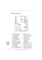 4
4 -
 5
5 -
 6
6 -
 7
7 -
8
-
9
-
10
-
11
-
12
-
13
-
14
-
15
-
16
-
17
-
18
-
19
-
20
-
21
-
22
-
23
-
24
-
25
-
26
-
27
-
28
-
29
-
30
-
31
-
32
-
33
-
34
-
35
-
36
-
37
-
38
-
39
-
40
-
41
-
42
-
43
-
44
-
45
-
46
-
47
-
48
-
49
-
50
-
51
-
52
-
53
-
54
-
55
-
56
-
57
-
58
-
59
-
60
-
61
-
62
-
63
-
64
-
65
-
66
-
67
-
68
-
69
-
70
-
71
-
72
-
73
-
74
-
75
-
76
-
77
-
78
-
79
-
80
-
81
-
82
-
83
-
84
-
85
-
86
-
87
-
88
-
89
-
90
-
91
-
92
-
93
-
94
-
95
-
96
-
97
-
98
-
99
-
100
-
101
-
102
-
103
-
104
-
105
-
106
-
107
-
108
-
109
-
110
-
111
-
112
-
113
-
114
-
115
-
116
-
117
-
118
-
119
-
120
-
121
-
122
-
123
-
124
-
125
-
126
-
127
-
128
-
129
-
130
-
131
-
132
-
133
-
134
-
135
-
136
-
137
-
138
-
139
-
140
-
141
-
142
-
143
-
144
-
145
-
146
-
147
-
148
-
149
-
150
-
151
-
152
-
153
-
154
-
155
-
156
-
157
-
158
-
159
-
160
-
161
-
162
-
163
-
164
-
165
-
166
-
167
-
168
-
169
-
170
-
171
-
172
-
173
-
174
-
175
-
176
-
177
-
178
-
179
-
180
-
181
-
182
-
183
-
184
-
185
-
186
-
187
-
188
-
189
-
190
-
191
-
192
-
193
-
194
-
195
-
196
-
197
-
198
-
199
-
200
-
201
-
202
-
203
-
204
-
205
-
206
-
207
-
208
-
209
-
210
-
211
-
212
-
213
-
214
-
215
-
216
-
217
-
218
-
219
-
220
-
221
-
222
-
223
-
224
-
225
-
226
-
227
-
228
-
229
-
230
-
231
-
232
-
233
-
234
-
235
-
236
-
237
-
238
-
239
-
240
-
241
-
242
-
243
 |
 |

Fatal1ty Z77 Professional Series Motherboard
1
English
Who knew that at age 19, I would be a World Champion PC gamer. When I was 13, I
actually played competitive billiards in professional tournaments and won four or five
games off guys who played at the highest level. I actually thought of making a career
of it, but at that young age situations change rapidly. Because I’ve been blessed with
great hand-eye coordination and a grasp of mathematics (an important element in video
gaming) I gravitated to that activity.
GOING PRO
I started professional gaming in 1999 when I entered the CPL (Cyberathlete Professional
League) tournament in Dallas and won $4,000 for coming in third place. Emerging as one
of the top players in the United States, a company interested in sponsoring me
fl
ew me
to Sweden to compete against the top 12 players in the world. I won 18 straight games,
lost none, and took
fi
rst place, becoming the number one ranked Quake III player in the
world in the process. Two months later I followed that success by traveling to Dallas
and defending my title as the world’s best Quake III player, winning the $40,000 grand
prize. From there I entered competitions all over the world, including Singapore, Korea,
Germany, Australia, Holland and Brazil in addition to Los Angeles, New York and St.
Louis.
WINNING STREAK
I was excited to showcase my true gaming skills when defending my title as CPL
Champion of the year at the CPL Winter 2001 because I would be competing in a totally
different first person shooter (fps) game, Alien vs. Predator II. I won that competition
and walked away with a new car. The next year I won the same title playing Unreal
Tournament 2003, becoming the only three-time CPL champion of the year. And I did it
playing a different game each year, something no one else has ever done and a feat of
which I am extremely proud.
At QuakeCon 2002, I faced off against my rival ZeRo4 in one of the most highly
anticipated matches of the year, winning in a 14 to (-1) killer victory. Competing at
Quakecon 2004, I became the World’s 1st Doom3 Champion by defeating Daler in a
series of very challenging matches and earning $25,000 for the victory.
Since then Fatal1ty has traveled the globe to compete against the best in the world,
winning prizes and acclaim, including the 2005 CPL World Tour Championship in New
York City for a $150,000
fi
rst place triumph. In August 2007, Johnathan was awarded the
fi
rst ever Lifetime Achievement Award in the four year history of the eSports-Award for
“showing exceptional sportsmanship, taking part in shaping eSports into what it is today
and for being the prime representative of this young sport. He has become the
fi
gurehead
for eSports worldwide”.
Fatal1ty Story