ASRock Fatal1ty Z87 Killer Quick Installation Guide
ASRock Fatal1ty Z87 Killer Manual
 |
View all ASRock Fatal1ty Z87 Killer manuals
Add to My Manuals
Save this manual to your list of manuals |
ASRock Fatal1ty Z87 Killer manual content summary:
- ASRock Fatal1ty Z87 Killer | Quick Installation Guide - Page 1
change without notice, and should not be constructed as a commitment by ASRock. ASRock assumes no responsibility for any errors or omissions that may appear in CALIFORNIA, USA ONLY The Lithium battery adopted on this motherboard contains Perchlorate, a toxic substance controlled in Perchlorate Best - ASRock Fatal1ty Z87 Killer | Quick Installation Guide - Page 2
The terms HDMI™ and HDMI High-Definition Multimedia Interface, and the HDMI logo are trademarks or registered trademarks of HDMI Licensing LLC in the United States and other countries. Manufactured under license under U.S. Patent Nos: 5,956,674; 5,974,380; 6,487,535; 7,003,467 & other U.S. and - ASRock Fatal1ty Z87 Killer | Quick Installation Guide - Page 3
professional gaming in 1999 when I entered the CPL (Cyberathlete Professional , Alien vs. Predator II killer victory. Competing at Quakecon 2004, I became the World's 1st Doom3 Champion by defeating Daler in a series of very challenging matches and earning $25,000 for the victory. Since then Fatal1ty - ASRock Fatal1ty Z87 Killer | Quick Installation Guide - Page 4
my drive to be the best has opened the doors necessary to become a professional. A DREAM Now, another dream is being realized - building the ultimate gaming and allowing more fluid movement around the maps. My vision for Fatal1ty hardware is to allow gamers to focus on the game without worrying - ASRock Fatal1ty Z87 Killer | Quick Installation Guide - Page 5
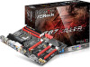
PCIE1 X Fast LAN 1 FATA L PWR_FAN1 TY Z87 KILLER PCIE2 PCIE3 SATA3_5 SATA3_4 RoHS Super I/O PCIE4 PCIE5 Intel Z87 PCIE6 CMOS Battery BIOS_A_LED1 BIOS_B_LED1 CLRCMOS1 1 HD_AUDIO1 1 COM1 1 IR1 1 PCIE7 SLI/XFIRE_PWR1 USB6_7 1 USB4_5 1 CHA_FAN1 64Mb BIOS BIOS_A1 1 BIOS_SEL1 - ASRock Fatal1ty Z87 Killer | Quick Installation Guide - Page 6
Header (PANEL1) 16 Chassis Speaker Header (SPEAKER1) 17 BIOS Selection Jumper (BIOS_SEL1) 18 Chassis Fan Connector (CHA_FAN1) 19 Clear CMOS Jumper (CLRCMOS1) 20 USB 2.0 Header (USB4_5) 21 USB 2.0 Header (USB6_7) 22 SLI/XFIRE Power Connector (SLI/XFIRE_PWR1) 23 Infrared Module Header (IR1) 24 COM - ASRock Fatal1ty Z87 Killer | Quick Installation Guide - Page 7
I/O Panel 1 2 Fatal1ty Z87 Killer Series 3 79 4 5 6 8 10 17 16 15 14 13 12 11 No. Description 1 USB 2.0 Ports (USB01) 2 D-Sub Port 3 Fatal1ty Mouse Port (USB2) 4 USB 2.0 Port (USB3) 5 USB 3.0 Ports (USB3_01) 6 LAN RJ-45 Port* 7 Central / Bass (Orange) 8 Rear Speaker (Black) 9 Line In - ASRock Fatal1ty Z87 Killer | Quick Installation Guide - Page 8
port. Please refer to the table below for the LAN port LED indications. ACT/LINK LED SPEED LED LAN Port Activity / Link LED Status Description Off Blinking On No Link Data Activity Link Speed LED Status Off Orange Green Description 10Mbps connection 100Mbps connection - ASRock Fatal1ty Z87 Killer | Quick Installation Guide - Page 9
and CPU support list on ASRock's website as well. ASRock website http://www.asrock.com. 1.1 Package Contents • ASRock Fatal1ty Z87 Killer Series Motherboard (ATX Form Factor) • ASRock Fatal1ty Z87 Killer Series Quick Installation Guide • ASRock Fatal1ty Z87 Killer Series Support CD • 4 x Serial ATA - ASRock Fatal1ty Z87 Killer | Quick Installation Guide - Page 10
/ i3 / Xeon® / Pentium® / Celeron® in LGA1150 package • Digi Power design • 8 Power Phase design • Supports Intel® Turbo Boost 2.0 Technology • Supports Intel® K-Series unlocked CPUs • Supports ASRock BCLK Full-range Overclocking Chipset • Intel® Z87 Memory • Dual Channel DDR3 Memory Technology - ASRock Fatal1ty Z87 Killer | Quick Installation Guide - Page 11
Fatal1ty Z87 Killer Series Expansion Slot • 3 x PCI Express 3.0 x16 Slots (PCIE2/PCIE5/PCIE7: single at x16 (PCIE2); dual at x8 (PCIE2) / x8 (PCIE5); triple at x8 (PCIE2) / x4 (PCIE5) / x4 (PCIE7)) • 4 x PCI Express 2.0 x1 Slots • Supports AMD Quad CrossFireXTM, 3-Way CrossFireXTM and CrossFireXTM - ASRock Fatal1ty Z87 Killer | Quick Installation Guide - Page 12
KillerTM E2200 Series • Supports Wake-On-LAN • Supports Energy Efficient Ethernet 802.3az • Supports PXE Rear Panel I/O • 1 x PS/2 Mouse/Keyboard Port • 1 x D-Sub Port • 1 x DVI-D Port • 1 x HDMI-Out Port • 1 x HDMI-In Port • 1 x Optical SPDIF Out Port • 3 x USB 2.0 Ports • 1 x Fatal1ty Mouse Port - ASRock Fatal1ty Z87 Killer | Quick Installation Guide - Page 13
Fatal1ty Z87 Killer Series BIOS Feature Support CD Hardware Monitor OS Certifications • 1 x SLI/XFire Power Connector • 1 x Front Panel Audio Connector • 2 x USB 2.0 Headers (Support 4 USB 2.0 ports) • 1 x USB 3.0 Header (Supports 2 USB 3.0 ports) • 2 x 64Mb AMI UEFI Legal BIOS with multilingual - ASRock Fatal1ty Z87 Killer | Quick Installation Guide - Page 14
risk involved with overclocking, including adjusting the setting in the BIOS, applying Untied Overclocking Technology, or using thirdparty overclocking tools. Overclocking may affect your have such limitations. You can use ASRock XFast RAM to utilize the memory that Windows® cannot use. 10 English - ASRock Fatal1ty Z87 Killer | Quick Installation Guide - Page 15
Fatal1ty Z87 Killer Series 1.3 Unique Features ASRock F-Stream F-Stream is ASRock's multi purpose software suite with a new interface, more new features and improved utilities, including XFast RAM, Dehumidifier, Good Night LED, FAN-Tastic Tuning, OC Tweaker and a whole lot more. ASRock Instant Flash - ASRock Fatal1ty Z87 Killer | Quick Installation Guide - Page 16
", then you can start installing the OS in RAID mode. ASRock Easy Driver Installer For users that don't have an optical disk drive to install the drivers from our support CD, Easy Driver Installer is a handy tool in the UEFI that installs the LAN driver to your system via an USB storage device, then - ASRock Fatal1ty Z87 Killer | Quick Installation Guide - Page 17
Fatal1ty Z87 Killer Series ASRock Restart to UEFI Windows® 8 brings the ultimate boot up experience. The lightning boot up speed makes it hard to access the UEFI setup. ASRock Restart to UEFI allows users to enter the UEFI automatically when turning on the PC. By enabling this function, the PC will - ASRock Fatal1ty Z87 Killer | Quick Installation Guide - Page 18
it. Pre-installation Precautions Take note of the following precautions before you install motherboard components or change any motherboard settings. • Make sure to unplug the power cord before installing or removing the motherboard. Failure to do so may cause physical injuries to you and damages to - ASRock Fatal1ty Z87 Killer | Quick Installation Guide - Page 19
Fatal1ty Z87 Killer Series 2.1 Installing the CPU 1. Before you insert the 1150-Pin CPU into the socket, please check if the PnP cap is on the socket, if the CPU surface is unclean, or if there are any bent pins in the socket. Do not force to insert the CPU into the socket if above situation is - ASRock Fatal1ty Z87 Killer | Quick Installation Guide - Page 20
4 5 16 3 English - ASRock Fatal1ty Z87 Killer | Quick Installation Guide - Page 21
Fatal1ty Z87 Killer Series Please save and replace the cover if the processor is removed. The cover must be placed if you wish to return the motherboard for after service. 17 English - ASRock Fatal1ty Z87 Killer | Quick Installation Guide - Page 22
2.2 Installing the CPU Fan and Heatsink 1 18 2 CPU_FAN English - ASRock Fatal1ty Z87 Killer | Quick Installation Guide - Page 23
Fatal1ty Z87 Killer Series 2.3 Installing Memory Modules (DIMM) This motherboard provides four 240-pin DDR3 (Double Data Rate 3) DIMM slots, and supports Dual Channel Memory Technology. 1. For dual channel configuration, you always need to install identical (the same brand, speed, size and chip- - ASRock Fatal1ty Z87 Killer | Quick Installation Guide - Page 24
1 2 3 20 English - ASRock Fatal1ty Z87 Killer | Quick Installation Guide - Page 25
Fatal1ty Z87 Killer Series 2.4 Expansion Slots (PCI Express Slots) There are 7 PCI Express slots on the motherboard. Before installing an expansion card, please make sure that the power supply is switched off or the power cord is unplugged. Please read the documentation of the expansion card and - ASRock Fatal1ty Z87 Killer | Quick Installation Guide - Page 26
setup, please turn off the computer and unplug the power cord from the power supply. After waiting for 15 seconds, use a jumper cap to short pin2 and pin3 on CLRCMOS1 for 5 seconds. However, please do not clear the CMOS right after you update the BIOS. If you need to clear the CMOS when you - ASRock Fatal1ty Z87 Killer | Quick Installation Guide - Page 27
Fatal1ty Z87 Killer Series BIOS Selection Jumper (BIOS_SEL1) (see p.1, No. 17) Default Backup BIOS (Main BIOS) This motherboard has two BIOS onboard, a main BIOS (BIOS_A) and a backup BIOS (BIOS_B), which enhances protection for the safety and stability of your system. Normally, the system works - ASRock Fatal1ty Z87 Killer | Quick Installation Guide - Page 28
jumper caps over the headers and connectors will cause permanent damage to the motherboard. System Panel Header (9-pin PANEL1) (see p.1, No. 15) PLED+ PLEDPWRBTN# GND 1 GND RESET# GND HDLEDHDLED+ Connect the power switch, reset switch and system status indicator on the chassis to this header - ASRock Fatal1ty Z87 Killer | Quick Installation Guide - Page 29
Fatal1ty Z87 Killer Series Power LED Header (3-pin PLED1) (see p.1, No. 14) 1 PLED- PLED+ PLED+ Serial ATA3 Connectors (SATA3_0: see p.1, No. 19) (SATA3_1: see p.1, No. 8) (SATA3_2: see are two headers on this motherboard. Each USB 2.0 header can support two ports. Vbus IntA_PA_SSRXIntA_PA_SSRX+ - ASRock Fatal1ty Z87 Killer | Quick Installation Guide - Page 30
supports Jack Sensing, but the panel wire on the chassis must support HDA to function correctly. Please follow the instructions in our manual and chassis manual Speaker Header (4-pin SPEAKER1) (see p.1, No. 16) Chassis and Power Fan Connectors (4-pin CHA_FAN1) (see p.1, No. 18) (3-pin CHA_FAN2 - ASRock Fatal1ty Z87 Killer | Quick Installation Guide - Page 31
Fatal1ty Z87 Killer Series CPU Fan Connectors (4-pin CPU_FAN1) (see p.1, No. 3) (3-pin CPU_FAN2) (see p.1, No. 2) ATX Power Connector (24-pin ATXPWR1) (see p.1, No. 6) ATX 12V Power Connector (8-pin ATX12V1) (see p.1, No. 1) SLI/XFIRE Power Connector (4-pin SLI/XFIRE_ PWR1) (see p.1, No. 22) - ASRock Fatal1ty Z87 Killer | Quick Installation Guide - Page 32
und Prozessoren auf der ASRock-Webseite: ASRock-Webseite http://www.asrock.com. 1.1 Lieferumfang • ASRock Fatal1ty Z87 Killer Series-Motherboard (ATX-Formfaktor) • ASRock Fatal1ty Z87 Killer Series-Schnellinstallationsanleitung • ASRock Fatal1ty Z87 Killer Series-Support-CD • 4 x Serial-ATA- (SATA - ASRock Fatal1ty Z87 Killer | Quick Installation Guide - Page 33
Fatal1ty Z87 Killer Series 1.2 Technische Daten Plattform • ATX-Formfaktor • Premium Gold-Kondensatordesign (100 % in Japan gefertigt, hochqualitative leitfähige Polymer-Kondensatoren) A-Stil • Purity SoundTM • HDMI-Eingang Gaming Armor CPU-Power • Hi-Density-Netzanschluss VGA-Karte • 15μGold - ASRock Fatal1ty Z87 Killer | Quick Installation Guide - Page 34
AVC, MVC (S3D) und MPEG2 Full HW Encode1, Intel® InTruTM 3D, Intel® Clear Video HD Technology, Intel® InsiderTM, Intel® HD Graphics 4600 • Pixel Shader 5.0, DirectX 11.1 • Max. geteilter Speicher: 1792 MB • Drei VGA-Ausgangsoptionen: D-Sub, DVI-D und HDMI • Unterstützt drei Monitore • Unterstützt - ASRock Fatal1ty Z87 Killer | Quick Installation Guide - Page 35
Fatal1ty Z87 Killer Series LAN Rückblende, E/A Speicher Anschluss - Direct Drive Technology - Abdeckung mit EMV-Abschirmung - PCB-isolierte Abschirmung • Unterstützt DTS Connect • PCIE x1 Gigabit LAN 10/100/1000 Mb/s • Qualcomm® Atheros® KillerTM E2200 Series • Unterstützt Wake-On-LAN • Unterstü - ASRock Fatal1ty Z87 Killer | Quick Installation Guide - Page 36
64-Mb-AMI-UEFI-Legal-BIOS mit Unterstützung mehrsprachiger grafischer Benutzerschnittstellen (1 x Haupt-BIOS und 1 x Ausfall-BIOS) • Unterstützt UEFI-Technologie ), XSplit, Killer Network Manager • CPU-/Gehäusetemperaturerkennung • CPU/Gehäuse/Netzteil-Lüftertachometer • Lautloser CPU-/Gehäuselüfter - ASRock Fatal1ty Z87 Killer | Quick Installation Guide - Page 37
Fatal1ty Z87 Killer Series Bitte beachten Sie, dass mit einer Übertaktung, zu der die Anpassung von BIOSEinstellungen, die Anwendung der Untied Overclocking Betriebssysteme mit 64 Bit haben keine derartigen Beschränkungen. Mit ASRock XFast RAM können Sie den Speicher einsetzen, den Windows® nicht - ASRock Fatal1ty Z87 Killer | Quick Installation Guide - Page 38
3 an CLRCMOS1 5 Sekunden lang mit einer Jumper-Kappe kurz. Löschen Sie den CMOS jedoch nicht direkt nach der BIOS-Aktualisierung. Falls Sie den CMOS direkt nach Abschluss der BIOS-Aktualisierung löschen müssen, starten Sie das System zunächst; fahren Sie es dann vor der CMOS-Löschung herunter. Bitte - ASRock Fatal1ty Z87 Killer | Quick Installation Guide - Page 39
Fatal1ty Z87 Killer Series BIOS-Auswahl-Jumper (BIOS_SEL1) (siehe S. 1, Nr. 17) Standard Ausfall-BIOS (Haupt-BIOS) Dieses Motherboard verfügt über zwei integrierte BIOS, ein Haupt-BIOS (BIOS_A) und ein Ausfall-BIOS (BIOS_B), die den Schutz in puncto Sicherheit und Stabilität Ihres Systems - ASRock Fatal1ty Z87 Killer | Quick Installation Guide - Page 40
diesen Stiftleisten und Anschlüssen an. Durch Anbringen von Jumper-Kappen an diesen Stiftleisten und Anschlüssen können Sie das Motherboard dauerhaft beschädigen. Systemblende-Stiftleiste (9-polig, PANEL1) (siehe S. 1, Nr. 15) Verbinden Sie Netzschalter, Reset-Taste und Systemstatusanzeige am Geh - ASRock Fatal1ty Z87 Killer | Quick Installation Guide - Page 41
Betrieb-LED-Stiftleiste (3-polig, PLED1) (siehe S. 1, Nr. 14) Serial-ATA-IIIAnschlüsse (SATA3_0: siehe S. 1, Nr. 19) (SATA3_1: SATA3_3 SATA3_1 SATA3_4 SATA3_2 SATA3_0 Fatal1ty Z87 Killer Series Bitte verbinden Sie die Betrieb-LED zwei Stiftleisten an diesem Motherboard. Jede USB 2.0-Stiftleiste - ASRock Fatal1ty Z87 Killer | Quick Installation Guide - Page 42
Audiostiftleiste (Frontblende) (9-polig, HD_AUDIO1) (siehe S. 1, Nr. 25) Diese Stiftleiste dient dem Anschließen von Audiogeräten an der Frontblende. 1. High Definition Audio unterstützt Anschlusserkennung, der Draht am Gehäuse muss dazu jedoch HDA unterstützt. Bitte befolgen Sie zum Installieren - ASRock Fatal1ty Z87 Killer | Quick Installation Guide - Page 43
Fatal1ty Z87 Killer Series CPU-Lüfteranschlüsse (4-polig, CPU_FAN1) (siehe S. 1, Nr. 3) (3-polig, CPU_FAN2) (siehe S. 1, Nr. 2) ATX-Netzanschluss (24-polig, ATXPWR1) (siehe S. 1, Nr. 6) 12 24 1 13 ATX-12-V-Netzanschluss (8-polig, ATX12V1) (siehe S. 1, Nr. 1) SLI/XFIRENetzanschluss (4-polig, - ASRock Fatal1ty Z87 Killer | Quick Installation Guide - Page 44
Serieller-Port-Stiftleiste (9-polig, COM1) (siehe S. 1, Nr. 24) Diese COM1-Stiftleiste unterstützt ein Modul für serielle Ports. Deutsch 40 - ASRock Fatal1ty Z87 Killer | Quick Installation Guide - Page 45
de ASRock. Site Internet ASRock http://www.asrock.com. 1.1 Contenu de l'emballage • Carte mère ASRock Série Fatal1ty Z87 Killer (facteur de forme ATX) • Guide d'installation rapide ASRock Série Fatal1ty Z87 Killer • CD d'assistance ASRock Série Fatal1ty Z87 Killer • 4 x câbles de données Serial ATA - ASRock Fatal1ty Z87 Killer | Quick Installation Guide - Page 46
® en package LGA1150 • Conception Digi Power • Alimentation à 8 phases • Prend en charge la technologie Intel® Turbo Boost 2.0 • Prend en charge les processeurs débloqués de la série K Intel® • Prend en charge l'overclocking ASRock BCLK Full-range Chipset • Intel® Z87 Mémoire • Technologie - ASRock Fatal1ty Z87 Killer | Quick Installation Guide - Page 47
Série Fatal1ty Z87 Killer Graphiques Audio • 4 x fente PCI Express 2.0 x1 • Prend en charge AMD Quad CrossFireXTM, 3-Way CrossFireXTM et CrossFireXTM • Prend en charge NVIDIA® Quad SLITM et SLITM • La technologie Intel® HD Graphics Built-in Visuals et les sorties VGA sont uniquement prises en - ASRock Fatal1ty Z87 Killer | Quick Installation Guide - Page 48
HDMI • 1 x port d'entrée HDMI • 1 x port sortie optique SPDIF • 3 x ports USB 2.0 • 1 x port souris Fatal1ty (USB 2.0) • 4 x ports USB 3.0 • 1 x port RJ-45 LAN ATX 24 broches • 1 x connecteur d'alimentation 12V 8 broches (connecteur d'alimentation haute densité) • 1 x connecteur d'alimentation SLI - ASRock Fatal1ty Z87 Killer | Quick Installation Guide - Page 49
Fatal1ty Z87 Killer Caractéristiques du BIOS CD inclus Surveillance du matériel Système d'exploitation Certifications • 2 x BIOS UEFI AMI 64Mo avec prise en charge interface graphique multilingue (1 x BIOS principal et 1 x BIOS : +12V, +5V, +3,3V, CPU Vcore • Compatible Microsoft® Windows® 8.1 - ASRock Fatal1ty Z87 Killer | Quick Installation Guide - Page 50
risques, incluant des modifications du BIOS, l'application d'une technologie d'overclocking déliée et l'utilisation d'outils d'overclocking développés par des tiers. La Windows® 64-bit. Vous pouvez utiliser ASRock XFast RAM pour utiliser la mémoire dont Windows® ne peut se servir. 46 Français - ASRock Fatal1ty Z87 Killer | Quick Installation Guide - Page 51
Série Fatal1ty Z87 Killer 1.3 Configuration des cavaliers (jumpers) L'illustration ci-dessous vous effacez pas la CMOS immédiatement après avoir mis à jour le BIOS. Si vous avez besoin d'effacer les données CMOS après une mise à jour du BIOS, vous devez tout d'abord redémarrer le système, puis - ASRock Fatal1ty Z87 Killer | Quick Installation Guide - Page 52
nouveau court-circuitage de la broche 1 et de la broche 2, puis utilisez "Secure Backup UEFI" depuis l'utilitaire de configuration du BIOS pour copier le fichier BIOS vers le BIOS principal et rétablir le fonctionnement normal du système. Par souci de sécurité du système, l'utilisateur ne peut pas - ASRock Fatal1ty Z87 Killer | Quick Installation Guide - Page 53
Série Fatal1ty Z87 Killer 1.4 Embases et connecteurs de la carte mère Les embases et connecteurs situés sur la carte NE SONT PAS des cavaliers. Ne placez JAMAIS de capuchons - ASRock Fatal1ty Z87 Killer | Quick Installation Guide - Page 54
Français Embase LED d'alimentation (PLED1 à 3 broches) (voir p.1, No. 14) Connecteurs Serial ATA3 (SATA3_0: voir p. 1, No. 19) (SATA3_1: (voir p.1, No. 8) (SATA3_2: (voir p.1, No. 11) (SATA3_3: voir p.1, No. 10) (SATA3_4: voir p.1, No. 13) (SATA3_5: voir p.1, No. 12) Embases - ASRock Fatal1ty Z87 Killer | Quick Installation Guide - Page 55
Série Fatal1ty Z87 Killer Embase audio du panneau frontal (HD_AUDIO1 à 9 broches) (voir p.1, No. é du châssis doit être compatible avec la HDA pour fonctionner correctement. Veuillez suivre les instructions figurant dans notre manuel et dans le manuel du châssis pour installer votre système. - ASRock Fatal1ty Z87 Killer | Quick Installation Guide - Page 56
(ATXPWR1 à 24 broches) (voir p.1, No. 6) 12 24 1 13 Connecteur d'alimentation ATX 12V (ATX12V1 à 8 broches) (voir p.1, No. 1) Connecteur d'alimentation SLI/XFire (SLI/XFIRE_PWR1 à 4 broches) (voir p.1, No. 22) Embase pour module infrarouge (IR1 à 5 broches) (voir p.1, No. 23) 52 Cette carte - ASRock Fatal1ty Z87 Killer | Quick Installation Guide - Page 57
Embase pour port série (COM1 à 9 broches) (voir p.1, No. 24) Série Fatal1ty Z87 Killer Cette embase COM1 prend en charge un module de port série. Français 53 - ASRock Fatal1ty Z87 Killer | Quick Installation Guide - Page 58
Web di ASRock. Sito Web di ASRock http://www.asrock.com. 1.1 Contenuto della confezione • Scheda madre serie Fatal1ty Z87 Killer ASRock (fattore di forma ATX) • Guida rapida di installazione serie Fatal1ty Z87 Killer ASRock • CD di supporto serie Fatal1ty Z87 Killer ASRock • 4 x cavi dati Serial ATA - ASRock Fatal1ty Z87 Killer | Quick Installation Guide - Page 59
4a generazione / Xeon® / Pentium® / Celeron® in LGA1150 Package • Design Digi Power • 8 Power Phase Design • Supporta la tecnologia Intel® Turbo Boost 2.0 • Supporta Intel® K-Series unlocked CPU • Supporta gamma completa overclocking BCLK ASRock • Intel® Z87 Memoria Slot di espansione • Tecnologia - ASRock Fatal1ty Z87 Killer | Quick Installation Guide - Page 60
NVIDIA® Quad SLITMe SLITM • La videografica integrata della scheda video HD Intel® e le uscite VGA possono essere supportate soltanto con processori con GPU integrata. • Supporta la videografica integrata della scheda video HD Intel®: Intel® Quick Sync Video con AVC, MVC (S3D) e MPEG-2 Full HW - ASRock Fatal1ty Z87 Killer | Quick Installation Guide - Page 61
Serie Fatal1ty Z87 Killer LAN I/O pannello posteriore Archiviazione Connettore • Supporta DTS Connect • PCIE x1 LAN Gigabit 10/100/1000 Mb/s • Qualcomm® Atheros® KillerTM E2200 Serie • Supporta Wake-On-LAN • Supporta Energy Efficient Ethernet 802.3az • Supporta PXE • 1 x porta mouse/tastiera PS/2 - ASRock Fatal1ty Z87 Killer | Quick Installation Guide - Page 62
2.3.1 • Multiregolazione tensione CPU, DRAM, PCH 1,05 V, PCH 1,5 V • Driver, Utilità, software antivirus (versione di prova), browser e barra degli strumenti Google Chrome, Start8 (30 giorni di prova), XSplit, Killer Network Manager • Sensore temperatura CPU/chassis • Tachimetro CPU/chassis/ventola - ASRock Fatal1ty Z87 Killer | Quick Installation Guide - Page 63
Serie Fatal1ty Z87 Killer Prestare attenzione al potenziale rischio previsto nella pratica di overclocking, inclusa la regolazione delle impostazioni nel BIOS, l'applicazione di tecnologia di Untied Overclocking o l'utilizzo di strumenti di overclocking di terze parti. L'overclocking può influenzare - ASRock Fatal1ty Z87 Killer | Quick Installation Guide - Page 64
il pin2 e il pin3 su CLRCMOS1 per 5 secondi. Tuttavia, non azzerare la CMOS subito dopo aver aggiornato il BIOS. Se è necessario azzerare la CMOS dopo l'aggiornamento del BIOS, è necessario riavviare prima il sistema e in seguito spegnerlo prima di eseguire l'operazione di azzeramento della CMOS. La - ASRock Fatal1ty Z87 Killer | Quick Installation Guide - Page 65
Serie Fatal1ty Z87 Killer Jumper di selezione BIOS (BIOS_SEL1) (vedere pag. 1, n. 17) Predefinito BIOS di backup (BIOS principale) Questa scheda madre è dotata di due BIOS, un BIOS principale (BIOS_A) e un BIOS di backup (BIOS_B), che migliorano la protezione, la sicurezza e la stabilità del - ASRock Fatal1ty Z87 Killer | Quick Installation Guide - Page 66
1.4 Header e connettori sulla scheda Gli header e i connettori sulla scheda NON sono jumper. NON posizionare cappucci del jumper su questi header e connettori. Il posizionamento di cappucci del jumper su header e connettori provocherà danni permanenti alla scheda madre. Header sul pannello del - ASRock Fatal1ty Z87 Killer | Quick Installation Guide - Page 67
LED di alimentazione (PLED1 a 3 pin) (vedere pag. 1, n. 14) Connettori Serial ATA3 (SATA3_0: vedere pag.1, n. 19) (SATA3_1: vedere pag. 1, n. 8) 1, n. 7) SATA3_5 SATA3_3 SATA3_1 SATA3_4 SATA3_2 SATA3_0 Italiano Serie Fatal1ty Z87 Killer Collegare il LED di alimentazione chassis a questo header per - ASRock Fatal1ty Z87 Killer | Quick Installation Guide - Page 68
Jack sensing, ma il filo del pannello sullo chassis deve supportare HDA per funzionare correttamente. Seguire le istruzioni presenti nel nostro manuale e nel manuale dello chassis per installare il sistema. 2. Se si utilizza un pannello audio AC'97, installarlo sull'header audio del pannello - ASRock Fatal1ty Z87 Killer | Quick Installation Guide - Page 69
Serie Fatal1ty Z87 Killer Connettori della ventola della CPU (CPU_FAN1 a 4 pin) (vedere pag. 1, n. 3) (CPU_FAN2 a 3 pin) (vedere pag. 1, n. 2) Connettore di alimentazione ATX (ATXPWR1 a 24 pin) (vedere pag. 1, n. 6) 12 24 1 13 Connettore di alimentazione ATX da 12 V (ATX12V1 a 8 pin) (vedere - ASRock Fatal1ty Z87 Killer | Quick Installation Guide - Page 70
Header porta seriale (COM1 a 9 pin) (vedere pag. 1, n. 24) Questo header COM1 supporta un modulo di porta seriale. Italiano 66 - ASRock Fatal1ty Z87 Killer | Quick Installation Guide - Page 71
de la CPU, en el sitio web de ASRock. Sitio web de ASRock http://www.asrock.com. 1.1 Contenido del paquete • Placa base ASRock Fatal1ty Z87 Killer Series (Factor de forma ATX) • Guía de instalación rápida de ASRock Fatal1ty Z87 Killer Series • CD de soporte de ASRock Fatal1ty Z87 Killer Series - ASRock Fatal1ty Z87 Killer | Quick Installation Guide - Page 72
® en paquete LGA1150 • Diseño Digi Power • Diseño de 8 fases de alimentación • Compatible con la tecnología de Intel® Turbo Boost 2.0 • Compatible con CPU serie K desbloqueada de Intel® • Compatible con overclocking de rango completo BCLK de ASRock Español Conjunto de chips • Intel® Z87 Memoria - ASRock Fatal1ty Z87 Killer | Quick Installation Guide - Page 73
Fatal1ty Z87 Killer Series Gráficos Audio • 4 ranura PCI Express 2.0 x1 • Compatible con AMD Quad CrossFireXTM, 3-Way CrossFireXTM y CrossFireXTM • Compatible con NVIDIA® Quad SLITM y SLITM • La Tecnología visual integrada de gráficos HD de Intel® y las salidas de VGA son compatibles únicamente - ASRock Fatal1ty Z87 Killer | Quick Installation Guide - Page 74
HDMI • 1 puerto de entrada HDMI • 1 puerto de salida SPDIF óptica • 3 puertos USB 2.0 • 1 puerto de ratón Fatal1ty (USB 2.0) • 4 puertos USB 3.0 • 1 puerto LAN ATX de 24 pines • 1 conector de alimentación de 8 pines y 12V (conector de alimentación de alta densidad) • 1 conector de alimentación SLI - ASRock Fatal1ty Z87 Killer | Quick Installation Guide - Page 75
Fatal1ty Z87 Killer Series Características del BIOS CD de soporte Monitor del hardware SO Certificaciones • 2 BIOS Legal UEFI AMI de 64Mb compatibles con interfaz gráfica de usuario multilingüe (1 BIOS Principal y 1 BIOS de copia de seguridad) • Compatible con tecnología UEFI de copia de seguridad - ASRock Fatal1ty Z87 Killer | Quick Installation Guide - Page 76
overclocking (sobreaceleración), incluyendo el ajuste de la configuración del BIOS, aplicando la Tecnología overcloking no vinculada o utilizando las herramientas de overclocking de tercera parte. El overclocking XFast RAM de ASRock para usar la memoria que Windows® no puede utilizar. 72 Español - ASRock Fatal1ty Z87 Killer | Quick Installation Guide - Page 77
Fatal1ty Z87 Killer Series 1.3 Instalación de los puentes La instalación muestra cómo deben , no borre el CMOS justo después de que haya actualizado el BIOS. Si necesita borrar el CMOS cuando acabe de actualizar el BIOS, deberá arrancar el sistema primero y, a continuación, deberá apagarlo antes - ASRock Fatal1ty Z87 Killer | Quick Installation Guide - Page 78
el correcto funcionamiento del sistema. Para garantizar la seguridad del sistema, los usuarios no pueden actualizar el BIOS de copia de seguridad de forma manual. Los usuarios podrán consultar el indicador LED del BIOS (BIOS_A_LED o BIOS_B_LED) para identificar qué BIOS está activado. Español 74 - ASRock Fatal1ty Z87 Killer | Quick Installation Guide - Page 79
Fatal1ty Z87 Killer Series 1.4 Conectores y cabezales incorporados Los cabezales y conectores incorporados NO son puentes. NO coloque tapas de puente sobre estos cabezales y conectores. Si coloca tapas de puente sobre - ASRock Fatal1ty Z87 Killer | Quick Installation Guide - Page 80
Español Cabezal de indicador LED de alimentación (PLED1 de 3 pines) (consulte la pág.1, N.º 14) Conectores Serie ATA3 (SATA3_0: consulte la pág.1, N.º 19) (SATA3_1: consulte la pág.1, N.º 8) (SATA3_2: consulte la pág.1, N.º 11) (SATA3_3: consulte la pág.1, N.º 10) (SATA3_4: consulte la pág.1, N.º - ASRock Fatal1ty Z87 Killer | Quick Installation Guide - Page 81
de 9 pines) (consulte la pág.1, N.º 25) Fatal1ty Z87 Killer Series Este cabezal se utiliza para conectar dispositivos de audio al que pueda funcionar correctamente. Siga las instrucciones que se indican en nuestro manual y en el manual del chasis para instalar su sistema. 2. Si utiliza un panel de - ASRock Fatal1ty Z87 Killer | Quick Installation Guide - Page 82
(ATXPWR1 de 24 pines) (consulte la pág.1, N.º 6) 12 24 1 13 Conector de alimentación ATX de 12V (ATX12V1 de 8 pines) (consulte la pág.1, N.º 1) Conector de alimentación SLI/XFIRE (SLI/XFIRE_PWR1 de 4 pines) (consulte la pág.1, N.º 22) Cabezal de módulo infrarrojo (IR1 de 5 pines) (consulte la - ASRock Fatal1ty Z87 Killer | Quick Installation Guide - Page 83
Cabezal de puerto serie (COM1 de 9 pines) (consulte la pág.1, N.º 24) Fatal1ty Z87 Killer Series Este cabezal COM1 admite un módulo de puerto serie. Español 79 - ASRock Fatal1ty Z87 Killer | Quick Installation Guide - Page 84
1 ASRock Fatal1ty Z87 Killer ASRock ASRock BIOS ASRock ASRock VGA ASRock http://www.asrock.com. 1.1 ASRock Fatal1ty Z87 Killer ATX ASRock Fatal1ty Z87 Killer ASRock Fatal1ty Z87 Killer • 4 Serial ATA (SATA 1 1 x карта ASRock SLI_Bridge_2S 80 - ASRock Fatal1ty Z87 Killer | Quick Installation Guide - Page 85
Серия Fatal1ty Z87 Killer 1.2 ATX Premium Gold Capacitor A-Style • Purity SoundTM HDMI VGA • 15μGold Finger VGA PCIe (PCIE2 SLI/XFire Qualcomm® Atheros® KillerTM LAN Purity SoundTM ЦП 4 Intel® CoreTM i7 / i5 / i3 / Xeon® / Pentium® / Celeron LGA1150 • Digi Power - ASRock Fatal1ty Z87 Killer | Quick Installation Guide - Page 86
Sync Video с AVC, MVC (S3D) и MPEG-2 Full HW Encode1, Intel® InTruTM 3D, Intel® Clear Video HD Technology, Intel® InsiderTM, Intel® HD Graphics 4600 • Pixel Shader 5.0, DirectX 11.1 1792 VGA: D-Sub, DVI-D и HDMI HDMI 4K × 2K (4096x2304) при 24 DVI-D 1920x1200 при 60 D-Sub 1920x1200 - ASRock Fatal1ty Z87 Killer | Quick Installation Guide - Page 87
Серия Fatal1ty Z87 Killer ЛВС • PCIE x1 Gigabit LAN 10/100/1000 Qualcomm® Atheros® KillerTM E2200 Wake-On-LAN Energy Efficient Ethernet 802.3az PXE • 1 x PS/2 1 x D-Sub • 1 x DVI-D • 1 x HDMI 1 x HDMI 1 x SPDIF • 3 x USB 2.0 • 1 x Fatal1ty USB 2.0) • 4 x USB 3.0 • 1 x RJ-45 ACT/ - ASRock Fatal1ty Z87 Killer | Quick Installation Guide - Page 88
и 1 x BIOS UEFI ACPI 1.1 SMBIOS 2.3.1 DRAM, PCH 1,05 В, PCH 1,5 В Google Chrome, Start8 30 дней), XSplit, Killer Network Manager 12 В, +5 В, +3,3 В, ЦП Vcore • Microsoft® Windows® 8.1 32 8.1 64 8 32 8 64 7 32 7 64 • FCC, CE, WHQL ErP/EuP ErP/EuP) http://www.asrock.com - ASRock Fatal1ty Z87 Killer | Quick Installation Guide - Page 89
Серия Fatal1ty Z87 Killer BIOS Untied Overclocking Technology 32 Windows 4 64 Windows Windows ASRock XFast RAM. 85 - ASRock Fatal1ty Z87 Killer | Quick Installation Guide - Page 90
1.3 3 1 и 2 CMOS (CLRCMOS1 1, № 19) CMOS CLRCMOS1 CMOS 15 2 и 3 на CLRCMOS1 на 15 CMOS BIOS CMOS BIOS CMOS CMOS. 86 - ASRock Fatal1ty Z87 Killer | Quick Installation Guide - Page 91
Серия Fatal1ty Z87 Killer BIOS (BIOS_SEL1 1, № 17) BIOS BIOS) BIOS BIOS (BIOS_A) и BIOS BIOS_B BIOS BIOS 2 3 BIOS 1 2 BIOS Secure Backup UEFI BIOS BIOS BIOS BIOS BIOS (BIOS_A_LED или BIOS_B_LED). 87 - ASRock Fatal1ty Z87 Killer | Quick Installation Guide - Page 92
1.4 9 PANEL1 1, № 15) PWRBTN RESET PLED S1/S3 S4 S5 HDLED 88 - ASRock Fatal1ty Z87 Killer | Quick Installation Guide - Page 93
№ 14) Serial ATA3 (SATA3_0 1, № 19) (SATA3_1 1, № 8) (SATA3_2 1, № 11) (SATA3_3 1, № 10) (SATA3_4 1, № 13) (SATA3_5 1, № 12) USB 2.0. (9 USB4_5 1, № 20) (9 USB6_7 1, № 21) USB 3.0. (19 USB3_4_5 1, № 7) SATA3_5 SATA3_3 SATA3_1 SATA3_4 SATA3_2 SATA3_0 Серия Fatal1ty Z87 Killer - ASRock Fatal1ty Z87 Killer | Quick Installation Guide - Page 94
9 HD_ AUDIO1 1, № 25) 1 HDA 2 AC'97 A Mic_IN (MIC) к MIC2_L. B Audio_R (RIN) к OUT2_R, Audio_L (LIN) к OUT2_L. C GND GND). D MIC_RET и OUT_RET AC'97 E FrontMic Realtek Recording Volume 4 SPEAKER1 1, № 16) 4 CHA_ FAN1 1, № 18) (3 CHA_ FAN2 1, № 28) (3 CHA_ - ASRock Fatal1ty Z87 Killer | Quick Installation Guide - Page 95
Серия Fatal1ty Z87 Killer 4 CPU_ FAN1 1, № 3) (3 CPU_ FAN2 1, № 2) 24 ATXPWR1 1, № 6) 12 24 1 13 12 В (8 ATX12V1 1, № 1) SLI/ XFIRE (4 SLI/ XFIRE_PWR1 1, № 22) 5 IR1 1, № 23) 4 3 1-3. 24 20 ATX 1 13. 8 12 4 ATX 1 5. 91 - ASRock Fatal1ty Z87 Killer | Quick Installation Guide - Page 96
9 COM1 1, № 24) COM1 92 - ASRock Fatal1ty Z87 Killer | Quick Installation Guide - Page 97
site da ASRock. Web site da ASRock http://www.asrock.com. 1.1 Conteúdo da embalagem • Placa principal ASRock Fatal1ty Z87 Killer Series (Formato ATX) • Guia de instalação rápida da ASRock Fatal1ty Z87 Killer Series • CD de suporte da ASRock Fatal1ty Z87 Killer Series • 4 x Cabos de dados Serial ATA - ASRock Fatal1ty Z87 Killer | Quick Installation Guide - Page 98
Pentium® / Celeron® de 4ª geração em socket LGA1150 • Design Digi Power • Design com 8 fases de alimentação • Suporta a tecnologia Intel® Turbo Boost 2.0 • Suporta CPU desbloqueado da série K da Intel® • Suporta Overclocking total ASRock BCLK Chipset • Intel® Z87 Memória • Tecnologia de memória - ASRock Fatal1ty Z87 Killer | Quick Installation Guide - Page 99
Fatal1ty Z87 Killer Series Ranhuras de expansão Gráficos • 3 x ranhuras PCI Express Intel® InTruTM 3D, Tecnologia Intel® Clear Video HD, Intel® InsiderTM, Gráficos Intel® HD 4600 • Pixel Shader 5.0, DirectX 11.1 • Memória partilhada máxima de 1792MB • Três opções de saída VGA: D-Sub, DVI-D e HDMI - ASRock Fatal1ty Z87 Killer | Quick Installation Guide - Page 100
® KillerTM E2200 Series • Suporta Wake-On-LAN • Suporta IEEE 802.3az • Suporta PXE • 1 x Porta PS/2 para rato/teclado • 1 x Porta D-Sub • 1 x Porta DVI-D • 1 x porta de saída HDMI • 1 x porta de entrada HDMI • 1 x Porta de saída SPDIF óptica • 3 x portas USB 2.0 • 1 x Porta para rato Fatal1ty (USB - ASRock Fatal1ty Z87 Killer | Quick Installation Guide - Page 101
Fatal1ty Z87 Killer Series Conector Funcionalidades da BIOS CD de suporte Monitor de hardware Sistema Operativo • 1 x Terminal IV • 1 x Terminal de porta COM • 1 x Conector para LED de alimentação • 2 x Conectores da ventoinha da CPU (1 x 4 pinos, 1 x 3 pinos) • 3 x Conectores da ventoinha do - ASRock Fatal1ty Z87 Killer | Quick Installation Guide - Page 102
Web site: http://www.asrock.com Tenha em atenção que o overclocking inclui um determinado grau de risco, incluindo o ajuste das definições na BIOS, a aplicação de tecnologia Untied Overclocking ou a utilização de ferramentas de overclocking de terceiros. O overclocking poderá afectar a estabilidade - ASRock Fatal1ty Z87 Killer | Quick Installation Guide - Page 103
Fatal1ty Z87 Killer Series 1.3 Configuração dos jumpers A imagem abaixo ilustra como os jumpers são configurados o CMOS logo após ter efectuado a actualização da BIOS. Se precisar de limpar o CMOS logo após ter terminado uma actualização da BIOS, deverá primeiro iniciar o sistema e voltar a encerrá- - ASRock Fatal1ty Z87 Killer | Quick Installation Guide - Page 104
tampa de jumper para colocar os pino2 e pino3 em "curto" e a BIOS de reserva irá assumir as funções no próximo reinício do sistema "Secure Backup UEFI" no utilitário de configuração da BIOS para copiar o ficheiro da BIOS para a BIOS principal para garantir o funcionamento normal do sistema. Por raz - ASRock Fatal1ty Z87 Killer | Quick Installation Guide - Page 105
Fatal1ty Z87 Killer Series 1.4 Terminais e conectores integrados Os terminais e conectores integrados NÃO são jumpers. NÃO coloque tampas de jumpers sobre estes terminais e conectores. Colocar tampas de jumpers sobre os terminais e conectores irá - ASRock Fatal1ty Z87 Killer | Quick Installation Guide - Page 106
Português Conector do LED de alimentação (PLED1 de 3 pinos) (consultar p.1, N.º 14) Conectores ATA3 de série (SATA3_0: consultar p.1, N.º 19) (SATA3_1: consultar p.1, N.º 8) (SATA3_2: consultar p.1, N.º 11) (SATA3_3: consultar p.1, N.º 10) (SATA3_4: consultar p.1, N.º 13) (SATA3_5: consultar p.1, - ASRock Fatal1ty Z87 Killer | Quick Installation Guide - Page 107
) Fatal1ty Z87 Killer Series Este terminal destina-se à ligação de dispositivos áudio ao painel de áudio frontal. Português 1. O Áudio de alta definição suporta Detecção de ficha, mas o cabo de painel no chassis deverá suportar HDA para funcionar correctamente. Siga as instruções no nosso manual - ASRock Fatal1ty Z87 Killer | Quick Installation Guide - Page 108
da CPU (CPU_FAN1 de 4 pinos) (consultar p.1, N.º 3) (CPU_FAN2 de 3 pinos) (consultar p.1, N.º 2) Conector de alimentação ATX (ATXPWR1 de 24 pinos) (consultar p.1, N.º 6) 12 24 1 13 Conector de alimentação de 12V ATX (ATX12V1 de 8 pinos) (consultar p.1, N.º 1) Conector de alimentação SLI/XFIRE - ASRock Fatal1ty Z87 Killer | Quick Installation Guide - Page 109
Terminal de porta de série (COM1 de 9 pinos) (consultar p.1, N.º 24) Fatal1ty Z87 Killer Series Este terminal COM1 suporta um módulo de porta de série. Português 105 - ASRock Fatal1ty Z87 Killer | Quick Installation Guide - Page 110
de ASRock'ın web sitesinden bulabilirsiniz. ASRock'ın web sitesi http://www.asrock.com. 1.1 Ambalaj İçeriği • ASRock Fatal1ty Z87 Killer Serisi Anakartı (ATX Form Faktörü) • ASRock Fatal1ty Z87 Killer Serisi Hızlı Kurulum Kılavuzu • ASRock Fatal1ty Z87 Killer Serisi Destek CD'si • 4 x Seri ATA - ASRock Fatal1ty Z87 Killer | Quick Installation Guide - Page 111
Fatal1ty Z87 Killer Serisi 1.2 Özellikler Platform A-Stili Oyun Zırhı CPU • ATX Form Faktörü • Premium Gold Sığa tasarımı (%100 Japon-malı kaliteli İletken Polimer Sığalar) • Purity SoundTM • HDMI-Girişi CPU Gücü • Yüksek Yoğunluklu Güç Bağlayıcısı VGA Kartı • VGA PCIe Yuvasında (PCIE2) 15μ Gold - ASRock Fatal1ty Z87 Killer | Quick Installation Guide - Page 112
) ve MPEG-2 Full HW Encode1, Intel® InTruTM 3D, Intel® Net Video HD Teknolojisi, Intel® InsiderTM, Intel® HD Graphics 4600 ile Intel® Quick Sync Video • Pixel Shader 5.0, DirectX 11.1 • Maksimum paylaşılan bellek 1792MB • Üç VGA Çıkışı seçeneği: D-Sub, DVI-D ve HDMI • Üçlü Monitör Desteği • 4K × 2K - ASRock Fatal1ty Z87 Killer | Quick Installation Guide - Page 113
Fatal1ty Z87 Killer Serisi Ses • İçerik Koruma Özelliği ile 7.1 CH HD Ses ( LAN Bağlantı Noktası (ACT/LINK LED ve SPEED LED) • HD Ses Jakı: Arka Hoparlör / Merkezi / Bas / Hat Girişi / Ön Hoparlör / Mikrofon Depolama • 6 x SATA3 6,0 Gb/s bağlayıcıları, RAID (RAID 0, RAID 1, RAID 5, RAID 10, Intel - ASRock Fatal1ty Z87 Killer | Quick Installation Guide - Page 114
LED bağlantısı • 2 x CPU Fan bağlayıcıları (1 x 4-pin, 1 x 3-pin) • 3 x Kasa Fanı konektörü (1 x 4-pin, 2 x 3-pin) • 1 x Güç Fanı bağlayıcısı (3-pin) • 1 x 24 pin ATX güç bağlayıcısı • 1 x 8 pin 12V güç bağlayıcısı (Yüksek Yoğunluklu Güç Ko- nektörü) • 1 x SLI/XFire güç bağlayıcısı • 1 x Ön panel - ASRock Fatal1ty Z87 Killer | Quick Installation Guide - Page 115
Fatal1ty Z87 Killer Serisi Belgeler • FCC, CE, WHQL • ErP/EuP için hazır (ErP/EuP için hazır güç beslemesi gerekli- dir) * Detaylı ürün bilgisi için, lütfen web sitemizi ziyaret edin: http://www.asrock.com Lütfen, BIOS ayarlarını düzenleme, Bağımsız Hız Aşırtma Teknolojinin uygulanması ya da üçü - ASRock Fatal1ty Z87 Killer | Quick Installation Guide - Page 116
ncelledikten hemen sonra temizlemeyin. BIOS'u güncelledikten hemen sonra CMOS'u temizlemeniz gerekirse, önce sistemi başlatın ve ardından CMOS temizleme işlemi öncesinde yeniden kapatın. Lütfen, parola, tarih, saat ve varsayılan kullanıcı profilinin yalnızca CMOS bataryası çıkarıldığında temizlenece - ASRock Fatal1ty Z87 Killer | Quick Installation Guide - Page 117
Fatal1ty Z87 Killer Serisi BIOS Seçme Bağlama Teli (BIOS_SEL1) (bkz. sf.1, No. 17) Varsayılan Yedek BIOS (Ana BIOS) Bu anakartta sisteminizin güvenliği ve kararlılığı için korumayı artıran ana BIOS (BIOS_A) ve yedek BIOS (BIOS_B) olmak üzere iki adet BIOS vardır. Normalde sistem ana BIOS'ta çal - ASRock Fatal1ty Z87 Killer | Quick Installation Guide - Page 118
1.4 Ekli Bağlantılar ve Bağlayıcılar Ekli bağlantılar ve bağlayıcılar bağlantı teli değildir. Bağlantı teli kapaklarını bu bağlantı ve bağlayıcılar üzerine yerleştirmeyin. Bağlantı teli kapaklarının bağlantılar ile bağlayıcılar üzerine yerleştirilmesi, anakarta kalıcı hasar verebilir. Sistem Paneli - ASRock Fatal1ty Z87 Killer | Quick Installation Guide - Page 119
LED Bağlantısı (3-pin PLED1) (bkz. sf.1, No. 14) Seri ATA3 Bağlayıcıları (SATA3_0: bkz. sf.1, No. 19) ( pin USB3_4_5) (bkz. sf.1, No. 7) SATA3_5 SATA3_3 SATA3_1 SATA3_4 SATA3_2 SATA3_0 Türkçe Fatal1ty Z87 Killer Serisi Sistemin güç durumunun belirtilmesi için lütfen güç LED'ini bu bağlantıya takın. - ASRock Fatal1ty Z87 Killer | Quick Installation Guide - Page 120
Ön Panel Ses Bağlantısı (9-pin HD_AUDIO1) (bkz. sf.1, No. 25) Bu bağlantı, ses aygıtlarının ön ses paneline bağlanması içindir. Türkçe 1. Yüksek Tanımlı Ses, Jak Algılama özelliğini destekler, ancak bu işlevin düzgün çalışabilmesi için kasa üzerindeki panel kablosunun HDA işlevini desteklemesi - ASRock Fatal1ty Z87 Killer | Quick Installation Guide - Page 121
Fatal1ty Z87 Killer Serisi CPU Fan Bağlayıcıları (4-pin CPU_FAN1) (bkz sf.1, No. 3) (3-pin CPU_FAN2) (bkz sf.1, No. 2) ATX Güç Bağlayıcısı (24-pin ATXPWR1) (bkz. sf.1, No. 6) 12 24 ATX 12V Güç Bağlayıcısı (8-pin ATX12V1) (bkz. sf.1, No. 1) 1 13 SLI/XFIRE Güç Bağlayıcısı (4 pinli SLI/XFIRE_ - ASRock Fatal1ty Z87 Killer | Quick Installation Guide - Page 122
Seri Bağlantı Noktası Bağlantısı (9-pin COM1) (bkz. sf.1, No. 24) Bu COM1 bağlantısı seri bağlantı yuvası modülünü destekler. Türkçe 118 - ASRock Fatal1ty Z87 Killer | Quick Installation Guide - Page 123
한국어 Fatal1ty Z87 Killer 시리즈 1 개요 ASRock Fatal1ty Z87 Killer ASRock ASRock BIOS ASRock ASRock VGA 카드와 CPU ASRock http://www.asrock.com. 1.1 • ASRock Fatal1ty Z87 Killer ATX ASRock Fatal1ty Z87 Killer ASRock Fatal1ty Z87 Killer CD ATA (SATA 4 I/O 1 개 • ASRock SLI_Bridge_2S 카드 1 개 - ASRock Fatal1ty Z87 Killer | Quick Installation Guide - Page 124
• ATX 100 • Purity SoundTM • HDMI- 입력 CPU VGA 카드 • VGA PCIe 슬롯에 15 μ Gold Finger 장착 (PCIE2) • SLI/XFire Qualcomm® Atheros® KillerTM LAN Purity SoundTM • LGA1150 4 세대 Intel® CoreTM i7 / i5 / i3 / Xeon® / Pentium® / Celeron® 지원 • Digi 8 Intel® Turbo Boost 2.0 Intel®K CPU 지원 • ASRock BCLK - ASRock Fatal1ty Z87 Killer | Quick Installation Guide - Page 125
Fatal1ty Z87 Killer 시리즈 한국어 오디오 • PCI Express 3.0 Intel® HD VGA 출력은 GPU • Intel® HD AVC, MVC (S3D) 및 MPEG-2 풀 HW Encode1 지원 Intel® Quick Sync Video, Intel® InTruTM 3D, Intel HD 기술 , Intel® InsiderTM, Intel® HD 4600 • Pixel Shader 5.0, DirectX 11.1 1792MB • VGA D-Sub, DVI-D 및 HDMI HDMI - ASRock Fatal1ty Z87 Killer | Quick Installation Guide - Page 126
RJ-45 LAN 포트 1 개 (ACT/LINK LED 및 SPEED LED) • HD • SATA3 6.0 Gb/s 커넥터 6 개가 RAID (RAID 0, RAID 1, RAID 5, RAID 10, Intel 12 및 Intel NCQ, AHCI • IR 헤더 1 개 • COM 1 LED 헤더 1 개 • CPU 2 개 (1 x 4 핀 , 1 x 3 3 개 (1 x 4 핀 , 2 x 3 1 개 (3 핀 ) • 24 핀 ATX 1 개 • 8 핀 12V 1 SLI/XFire 1 1 개 • USB - ASRock Fatal1ty Z87 Killer | Quick Installation Guide - Page 127
Fatal1ty Z87 Killer 시리즈 BIOS 기능 지원 CD OS 인증 GUI 지원 64Mb AMI UEFI Legal BIOS 2 BIOS 1 BIOS 1 개 ) UEFI ACPI 1.1 SMBIOS 2.3.1 지원 • CPU, DRAM, PCH 1,05V, PCH 1.5V Google Chrome Start8 (30 XSplit, Killer Network Manager • CPU CPU CPU CPU 정) • CPU 12V, +5V, +3.3V, CPU Vcore • - ASRock Fatal1ty Z87 Killer | Quick Installation Guide - Page 128
한 국 어 BIOS Untied Overclocking Technology Windows® 32 4GB Windows® 64 ASRock XFast RAM Windows 124 - ASRock Fatal1ty Z87 Killer | Quick Installation Guide - Page 129
Fatal1ty Z87 Killer 시리즈 1.3 3 1 과 핀 2 Clear CMOS 점퍼 (CLRCMOS1) (1 19 기본값 Clear CMOS CLRCMOS1 CMOS 15 CLRCMOS1 의 핀 2 와 핀 3 을 5 BIOS CMOS BIOS CMOS CMOS CMOS 한국어 125 - ASRock Fatal1ty Z87 Killer | Quick Installation Guide - Page 130
BIOS BIOS_SEL1) (1 17 BIOS ( 메인 BIOS) BIOS BIOS (BIOS_A BIOS (BIOS_B BIOS BIOS 2 와 핀 3 BIOS 1 과 핀 2 BIOS Secure Backup UEFI BIOS BIOS BIOS BIOS LED (BIOS_A_LED 또는 BIOS_B_LED BIOS 한 국 어 126 - ASRock Fatal1ty Z87 Killer | Quick Installation Guide - Page 131
Fatal1ty Z87 Killer 시리즈 1.4 (9 핀 PANEL1) (1 15 PWRBTN RESET PLED LED LED S1/S3 LED S4 S5 LED HDLED LED LED LED LED LED 한국어 127 - ASRock Fatal1ty Z87 Killer | Quick Installation Guide - Page 132
한 국 어 전원 LED 헤더 (3 핀 PLED1) (1 14 시리얼 ATA3 커넥터 (SATA3_0: 1 19 SATA3_1: (1 8 SATA3_2: (1 11 SATA3_3: 1 10 SATA3_4: 1 13 SATA3_5: 1 12 USB 2.0 헤더 (9 핀 USB4_5) (1 20 9 핀 USB6_7) (1 21 USB 3.0 헤더 (19 핀 USB3_4_5) (1 7 128 SATA3_5 SATA3_3 SATA3_1 SATA3_4 SATA3_2 SATA3_0 LED - ASRock Fatal1ty Z87 Killer | Quick Installation Guide - Page 133
(9 핀 HD_AUDIO1) (1 25 Fatal1ty Z87 Killer 시리즈 한국어 111 HDA 222 AC'97 A. Mic_IN (MIC) 을 MIC2_L B. Audio_R (RIN) 을 OUT2_R Audio_L (LIN) 을 OUT2_L C. 접지 (GND GND D. MIC_RET 및 OUT_RET 는 HD AC'97 E Realtek FrontMic Recording Volume 4 핀 - ASRock Fatal1ty Z87 Killer | Quick Installation Guide - Page 134
한 국 어 CPU 4 핀 CPU_FAN1) (1 3 (3 핀 CPU_FAN2) (1 2 ATX 24 핀 ATXPWR1) (1 6 12 24 1 13 ATX 12V 8 핀 ATX12V1) (1 1 SLI/XFIRE 4 핀 SLI/XFIRE_PWR1) (1 22 5 핀 IR1) (1 23 4 핀 CPU 3 핀 CPU 1-3 24 핀 ATX 20 핀 ATX 1 과 핀 13 8 핀 ATX 12V 4 핀 ATX 1 과 핀 5 130 - ASRock Fatal1ty Z87 Killer | Quick Installation Guide - Page 135
(9 핀 COM1) (1 24 Fatal1ty Z87 Killer 시리즈 이 COM1 한국어 131 - ASRock Fatal1ty Z87 Killer | Quick Installation Guide - Page 136
日本語 1 Fatal1ty Z87 Killer BIOS VGA CPU http://www.asrock.com. 1.1 Fatal1ty Z87 Killer ATX Fatal1ty Z87 Killer Fatal1ty Z87 Killer CD • 4 x ATA(SATA 1 x I/O 1 x SLI_Bridge_2S カード 132 - ASRock Fatal1ty Z87 Killer | Quick Installation Guide - Page 137
日本語 Fatal1ty Z87 Killerシリーズ 1.2 仕様 • ATX 100 A • Purity SoundTM • HDMI-IN CPU VGA VGA PCIe PCIE2)に 15 SLI/XFire Qualcomm® Atheros® KillerTM LAN 音声 • Purity SoundTM CPU • LGA1150 4 世代の Intel® CoreTM i7 / i5 / i3 / Xeon® / Pentium® / Celeron • 8 • Intel 2.0 - ASRock Fatal1ty Z87 Killer | Quick Installation Guide - Page 138
® Quick Sync Video、Intel® InTruTM 3D、Intel HD Intel TM、Intel® HD 4600 5.0、DirectX 11.1 1792MB • 3 つの VGA D-Sub、DVI-D、HDMI • 3 HDMI 4K × 2K (4096x2304)@24Hz • DVI-D 1920x1200 @60Hz • D-Sub 1920x1200 @60Hz • HDMI(HDMI 12bpc)、xvYCC、HBR • DVI-D と HDMI HDCP DVI-D と HDMI HD 1080p BD - ASRock Fatal1ty Z87 Killer | Quick Installation Guide - Page 139
Fatal1ty Z87 Killerシリーズ 日本語 LAN I/O • DTS • PCIE x1 LAN 10/100/1000 Mb/ 秒 • Qualcomm® Atheros® KillerTM E2200 802.3az PXE • 1 x PS/2 1 x D-Sub 1 x DVI-D 1 x HDMI-Out 1 x HDMI-In 1 x 光 SPDIF 3 x USB 2.0 1 x Fatal1ty USB 2.0) • 4 x USB 3.0 LED 付き 1 x RJ-45 LAN ACT/LINK LED と - ASRock Fatal1ty Z87 Killer | Quick Installation Guide - Page 140
機能 CD OS 認証 • 2 x 64Mb AMI UEFI Legal BIOS GUI 対応(1 x メイ ン BIOS と 1 x BIOS) UEFI ACPI 1.1 SMBIOS 2.3.1 CPU、DRAM、PCH 1.05V、PCH 1.5V Google Chrome Start8(30 XSplit、Killer Network Manager • CPU CPU CPU CPU CPU 12V、+5V、+3.3V、CPU Vcore • Microsoft® Windows® 8.1 32 8.1 64 8 32 - ASRock Fatal1ty Z87 Killer | Quick Installation Guide - Page 141
日本語 Fatal1ty Z87 Killerシリーズ BIOS Windows® 32 4GB Windows® 64 Windows XFast RAM 137 - ASRock Fatal1ty Z87 Killer | Quick Installation Guide - Page 142
日本語 1.3 3 1 とピン 2 CMOS CLRCMOS1) (p.1、No. 19 参照) CMOS CLRCMOS1 は、CMOS 15 CLRCMOS1 の ピン 2 とピン 3 5 BIOS CMOS BIOS CMOS CMOS CMOS 138 - ASRock Fatal1ty Z87 Killer | Quick Installation Guide - Page 143
Fatal1ty Z87 Killerシリーズ BIOS BIOS_SEL1) (p.1、No. 17 参照) BIOS BIOS) BIOS(BIOS_A BIOS(BIOS_B) の 2 つの BIOS BIOS BIOS 2 とピン 3 BIOS 1 とピン 2 BIOS Secure Backup UEFI BIOS BIOS BIOS BIOS BIOS LED (BIOS_A_LED または BIOS_B_LED 日本語 139 - ASRock Fatal1ty Z87 Killer | Quick Installation Guide - Page 144
日本語 1.4 9 1) (p.1、No. 15 参照) PWRBTN RESET PLED LED LED S1/S3 LED S4 S5 LED HDLED LED LED LED LED LED 140 - ASRock Fatal1ty Z87 Killer | Quick Installation Guide - Page 145
参照) USB 2.0 9 ピン USB4_5) (p.1、No. 20 9 ピン USB6_7) (p.1、No. 21 参照) USB 3.0 19 ピン USB3_4_5) (p.1、No. 7 参照) SATA3_5 SATA3_3 SATA3_1 SATA3_4 SATA3_2 SATA3_0 日本語 Fatal1ty Z87 Killerシリーズ LED これら 6 つの SATA3 6.0 Gb SATA I/O 4 つの USB 2.0 2 USB 2.0 2 I/O 4 つの USB 3.0 1 USB 3.0 2 141 - ASRock Fatal1ty Z87 Killer | Quick Installation Guide - Page 146
9 ピン HD_AUDIO1) (p.1、No. 25 参照) 日本語 111 HDA 222 AC'97 A. Mic_IN (MIC) を MIC2_L B. Audio_R (RIN) を OUT2_R に、Audio_L (LIN) を OUT2_L C GND GND D. MIC_RET と OUT_RET は、HD AC'97 E Realtek FrontMic 4 ピン SPEAKER1) (p.1、No. 16 参照) 4 ピン CHA_FAN1) (p.1、No. 18 参照) (3 ピン CHA_FAN2 - ASRock Fatal1ty Z87 Killer | Quick Installation Guide - Page 147
Fatal1ty Z87 Killerシリーズ CPU 4 ピン CPU_FAN1) (p.1、No. 3 参照) (3 ピン CPU_FAN2) (p.1、No. 2 参照) ATX 24 ピン ATXPWR1) (p.1、No. 6 参照) 12 24 1 13 ATX12V 8 ピン ATX12V1) (p.1、No. 1 参照) SLI/XFIRE 4 ピン SLI/XFIRE_ PWR1) (p.1、No. 22 参照) 5 ピン IR1) (p.1、No. 23 参照) 4 ピ ン CPU 3 ピンの CPU 1-3 24 ピン ATX - ASRock Fatal1ty Z87 Killer | Quick Installation Guide - Page 148
9 ピン COM1) (p.1、No. 24 参照) この COM1 日本語 144 - ASRock Fatal1ty Z87 Killer | Quick Installation Guide - Page 149
简体中文 Fatal1ty Z87 Killer 系列 1 简介 ASRock Fatal1ty Z87 Killer ASRock ASRock BIOS ASRock ASRock VGA 卡和 CPU ASRock 网站 http://www.asrock.com。 1.1 • ASRock Fatal1ty Z87 Killer ATX ASRock Fatal1ty Z87 Killer ASRock Fatal1ty Z87 Killer 4 x 串行 ATA (SATA 1 x I/O 面板 • 1 x ASRock - ASRock Fatal1ty Z87 Killer | Quick Installation Guide - Page 150
• ATX 100 器) • 115dB HDMI- 输入 CPU VGA 卡 • VGA PCIe 槽 (PCIE2) 中 15μGold Finger SLI/XFire Internet • Qualcomm® Atheros® KillerTM LAN 音頻 • 115dB • 支持 LGA1150 封装第 4 代 Intel® CoreTM i7 / i5 / i3 / Xeon® / Pentium® / Celeron® • Digi Power 8 Intel® Turbo Boost 2.0 Intel® K CPU • 支持 ASRock BCLK - ASRock Fatal1ty Z87 Killer | Quick Installation Guide - Page 151
Fatal1ty Z87 Killer 系列 简体中文 音频 • 3 x PCI Express 3.0 x16 槽 (PCIE2/PCIE5/PCIE7: 单:x16 (PCIE2):双 -x8 (PCIE2) / x8 (PCIE5);三 - x8 (PCIE2) / x4 (PCIE5) / x4 (PCIE7)) • 4 x PCI Express 2.0 x1 AMD Quad CrossFireXTM、3 向 CrossFireXTM 和 CrossFireXTM • 支持 NVIDIA® Quad SLITM 和 SLITM • 只有 GPU Intel® HD - ASRock Fatal1ty Z87 Killer | Quick Installation Guide - Page 152
RAID 0、RAID 1、 RAID 5、RAID 10、Intel Rapid Storage Technology 12 和 Intel Smart Response Technology)、NCQ、AHCI • 1 x IR 接脚 • 1 x COM 1 x 电源 LED 接脚 • 2 x CPU 1 x 4 针 , 1 x 3 针 ) • 3 x 1 x 4 针 , 2 x 3 针 ) • 1 x 3 针 ) • 1 x 24 针 ATX 1 x 8 针 12V 1 x SLI/XFire 1 x 2 x USB 2.0 4 个 USB 2.0 1 x USB - ASRock Fatal1ty Z87 Killer | Quick Installation Guide - Page 153
Fatal1ty Z87 Killer 系列 BIOS • 2 x 64Mb AMI UEFI Legal BIOS GUI 支持(1 x 主 BIOS 和 1 x 备份 BIOS) UEFI 技术 • ACPI 1.1 SMBIOS 2.3.1 支持 • CPU、DRAM、PCH 1.05V、PCH 1.5V Voltage Multi-adjustment) 支持光盘 Google Chrome Start8(30 XSplit、Killer Network Manager 硬件监控 • CPU CPU CPU CPU 速度) • CPU - ASRock Fatal1ty Z87 Killer | Quick Installation Guide - Page 154
简体中文 BIOS 4GB Windows® 32-bit Windows® 64-bit ASRock XFast RAM 来利用 Windows 150 - ASRock Fatal1ty Z87 Killer | Quick Installation Guide - Page 155
Fatal1ty Z87 Killer 系列 1.3 3 1 和针 脚 2 清除 CMOS 跳线 (CLRCMOS1) ( 见第 1 页,第 19 个 ) 默认 清除 CMOS CLRCMOS1 CMOS 15 CLRCMOS1 2 和针脚 3 短接 5 BIOS CMOS BIOS CMOS CMOS CMOS 简体中文 151 - ASRock Fatal1ty Z87 Killer | Quick Installation Guide - Page 156
BIOS BIOS_SEL1) ( 见第 1 页,第 17 个 ) 默认 备份 BIOS (主 BIOS) BIOS BIOS (BIOS_A BIOS (BIOS_ B BIOS BIOS 2 和 3 BIOS 2 和 3 BIOS Secure Backup UEFI" 将 BIOS BIOS BIOS BIOS LED (BIOS_A_LED or BIOS_B_LED BIOS 启动。 简体中文 152 - ASRock Fatal1ty Z87 Killer | Quick Installation Guide - Page 157
简体中文 1.4 Fatal1ty Z87 Killer 系列 9 针 PANEL1) ( 见第 1 页, 第 15 个) PWRBTN RESET PLED LED LED S1/ S3 LED S4 S5) 时,此 LED 熄灭。 HDLED LED LED 亮起。 LED LED 153 - ASRock Fatal1ty Z87 Killer | Quick Installation Guide - Page 158
简体中文 电源 LED 接脚 (3 针 PLED1) ( 见第 1 页,第 14 个 ) 串行 ATA3 接口 (SATA3_0: 见第 1 页, 第 19 个 ) (SATA3_1: 见第 1 页, 第 8 个 ) (SATA3_2: 见第 1 页, 第 11 个 ) (SATA3_3: 见第 1 页, 第 10 个 ) (SATA3_4: 见第 1 页, 第 13 个 ) (SATA3_5: 见第 1 页, 第 12 个 ) USB 2.0 接脚 (5 针 USB4_9) ( 见第 1 页,第 20 个 ) (9 针 USB6_7) ( 见第 1 页,第 21 个 ) USB 3.0 - ASRock Fatal1ty Z87 Killer | Quick Installation Guide - Page 159
简体中文 9 针 HD_AUDIO1) ( 见第 1 页,第 25 个 ) Fatal1ty Z87 Killer 系列 111 HDA 222 AC'97 A. 将 Mic_IN (MIC) 连接到 MIC2_L. B. 将 Audio_R (RIN) 连接到 OUT2_R,将 Audio_L (LIN) 连接到 OUT2_L. C GND GND)。 D. MIC_RET 和 OUT_RET AC'97 E Realtek FrontMic Recording Volume 4 针 SPEAKER1) ( 见第 1 页, 第 - ASRock Fatal1ty Z87 Killer | Quick Installation Guide - Page 160
) ( 见第 1 页, 第 2 个 ) ATX 24 针 ATXPWR1) ( 见第 1 页,第 6 个 ) ATX 12V 8 针 ATX12V1) ( 见第 1 页,第 1 个 ) 12 24 1 13 SLI/XFIRE 4 针 SLI/XFIRE_ PWR1 1 页,第 22 个) 5 针 IR1) ( 见第 1 页,第 23 个 ) 9 针 COM1) ( 见第 1 页,第 24 个 ) 4 针 CPU 3 针 CPU 1-3。 24 针 ATX 20 针 ATX 1 和 针脚 13 8 针 ATX 12V 4 针 ATX - ASRock Fatal1ty Z87 Killer | Quick Installation Guide - Page 161
Fatal1ty Z87 Killer 系列 SJ/T 11364-2006 10 年。 简体中文 圖一 鉛 (Pb) 鎘 (Cd) 汞 (Hg Cr(VI PBB PBDE) X O O O O O X O O O O O O SJ/T 11363-2006 X SJ/T 11363-2006 2002/95/EC 157 - ASRock Fatal1ty Z87 Killer | Quick Installation Guide - Page 162
繁體中文 1 簡介 Fatal1ty Z87 Killer ASRock ASRock BIOS ASRock ASRock VGA 卡及 CPU ASRock 網 站 http://www.asrock.com. 1.1 • ASRock Fatal1ty Z87 Killer ATX ASRock Fatal1ty Z87 Killer ASRock Fatal1ty Z87 Killer 4 x Serial ATA (SATA 1 x I/O 1 x ASRock SLI_Bridge_2S 卡 158 - ASRock Fatal1ty Z87 Killer | Quick Installation Guide - Page 163
Fatal1ty Z87 Killer 系列 1.2 規格 平台 • ATX 100 A-Style • Purity SoundTM 115dB HDMI 輸入 CPU VGA 卡 • 15μGold Finger 於 VGA PCIe 插槽 (PCIE2) • SLI/XFire Qualcomm® Atheros® KillerTM LAN 音訊 • Purity SoundTM 115dB CPU 4 代 Intel® CoreTM i7 / i5 / i3 / Xeon® / Pentium® / Celeron® (LGA1150 - ASRock Fatal1ty Z87 Killer | Quick Installation Guide - Page 164
HW Encode1 的 Intel Intel® InTruTM 3D, Intel® Clear Video HD Technology、Intel® InsiderTM、Intel® HD Graphics 4600 • Pixel Shader 5.0,DirectX 11.1 1792MB • 三個 VGA D-Sub、DVI-D 及 HDMI 4K × 2K (4096x2304) @ 24Hz HDMI 技術 1920x1200 @ 60Hz DVI-D 1920x1200 @ 60Hz D-Sub HDMI HDMI Auto Lip Sync - ASRock Fatal1ty Z87 Killer | Quick Installation Guide - Page 165
繁體中文 Fatal1ty Z87 Killer 系列 LAN 後面板 I/O • PCIE x1 Gigabit LAN 10/100/1000 Mb/s • Qualcomm® Atheros® KillerTM E2200 Energy Efficient Ethernet 802.3az • 支援 PXE • 1 x PS/2 1 x D-Sub 1 x DVI-D 1 x HDMI 1 x HDMI 1 x 光纖 SPDIF 3 x USB 2.0 1 x Fatal1ty USB 2.0) • 4 x USB 3.0 1 x RJ-45 LAN - ASRock Fatal1ty Z87 Killer | Quick Installation Guide - Page 166
支援 CD • 2 x 64Mb AMI UEFI Legal BIOS GUI 支援 (1 x 主 BIOS 及 1 x 備用 BIOS) UEFI 技術 • ACPI 1.1 SMBIOS 2.3.1 • CPU、DRAM、PCH 1.05V、PCH 1.5V Google Chrome Start8 (30 XSplit、Killer Network Manager • CPU CPU CPU CPU CPU 12V、+5V、+3.3V、CPU Vcore • Microsoft® Windows® 8.1 32 位元 / 8.1 64 - ASRock Fatal1ty Z87 Killer | Quick Installation Guide - Page 167
繁體中文 Fatal1ty Z87 Killer 系列 BIOS Windows® 32 4GB。Windows® 64 ASRock XFast RAM 運用 Windows 163 - ASRock Fatal1ty Z87 Killer | Quick Installation Guide - Page 168
繁體中文 1.3 3-pin pin1 及 pin2 清除 CMOS 跳線 (CLRCMOS1 1 19) 預設 清除 CMOS CLRCMOS1 清除 CMOS 15 CLRCMOS1 上的 pin2 及 pin3 短路約 5 BIOS CMOS BIOS CMOS CMOS CMOS 164 - ASRock Fatal1ty Z87 Killer | Quick Installation Guide - Page 169
Fatal1ty Z87 Killer 系列 BIOS BIOS_SEL1 1 17) 預設 備用 BIOS ( 主 BIOS) BIOS BIOS (BIOS_A) 與備用 BIOS (BIOS_ B BIOS BIOS pin2 與 pin3 BIOS pin1 與 pin2 BIOS Secure Backup UEFI」將 BIOS BIOS BIOS BIOS LED (BIOS_A_LED 或 BIOS_B_LED BIOS。 繁體中文 165 - ASRock Fatal1ty Z87 Killer | Quick Installation Guide - Page 170
繁體中文 1.4 (9-pin PANEL1 1 15) PWRBTN RESET PLED LED LED S1/S3 LED S4 S5) 時, LED HDLED LED LED LED LED LED 166 - ASRock Fatal1ty Z87 Killer | Quick Installation Guide - Page 171
繁體中文 電源 LED 排針 (3-pin PLED1 1 14) Serial ATA3 接頭 (SATA3_0 1 19) (SATA3_1 1 8) (SATA3_2 1 11) (SATA3_3 1 10) (SATA3_4 1 13) (SATA3_5 1 12) USB 2.0 排針 (9-pin USB4_5 1 20) (9-pin USB6_7 1 21) USB 3.0 排針 (19-pin USB3_4_5 1 7) Fatal1ty Z87 Killer 系列 LED 這六組 SATA3 SATA 6.0 Gb - ASRock Fatal1ty Z87 Killer | Quick Installation Guide - Page 172
(9-pin HD_AUDIO1 1 25) 繁體中文 111 Jack Sensing HDA 222 AC' 97 A. 將 Mic_IN (MIC) 連接至 MIC2_L。 B. 將 Audio_R (RIN) 連接至 OUT2_R 且將 Audio_L (LIN) 連接至 OUT2_L。 C GND GND)。 D. MIC_RET 及 OUT_RET 僅供 HD AC' 97 E Realtek FrontMic 4-pin SPEAKER1 1 16) 4-pin CHA_FAN1 1 18) (3-pin - ASRock Fatal1ty Z87 Killer | Quick Installation Guide - Page 173
繁體中文 Fatal1ty Z87 Killer 系列 CPU 4-pin CPU_FAN1 1 3) (3-pin CPU_FAN2 1 2) ATX 24-pin ATXPWR1 1 6) 12 24 ATX 12V 8-pin ATX12V1 1 1) 1 13 SLI/XFIRE 4-pin SLI/XFIRE_PWR1 1 22) 5-pin IR1 1 23) 9-pin COM1 1 24) 4-Pin CPU 3-Pin CPU Pin 1-3。 24pin ATX 20-pin ATX Pin 1 - ASRock Fatal1ty Z87 Killer | Quick Installation Guide - Page 174
di situs web ASRock. Situs web ASRock http://www.asrock.com. 1.1 Isi Kemasan • Motherboard ASRock Fatal1ty Z87 Killer Series (Bentuk dan Ukuran ATX) • Panduan Ringkas ASRock Fatal1ty Z87 Killer Series • CD Dukungan Panduan Ringkas ASRock Fatal1ty Z87 Killer Series • 4 x Kabel Data SATA (Serial ATA - ASRock Fatal1ty Z87 Killer | Quick Installation Guide - Page 175
Ke-4 / Xeon® / Pentium® / Celeron® dalam Paket LGA1150 • Desain Digi Power • Desain 8 Fase Daya • Mendukung Teknologi Intel® Turbo Boost 2.0 • Mendukung CPU Intel® K-Series unlocked • Mendukung Overclock Jarak penuh ASRock BCLK Chipset • Intel® Z87 Memori • Teknologi Memori DDR3 Kanal Ganda - ASRock Fatal1ty Z87 Killer | Quick Installation Guide - Page 176
AVC, MVC (S3D), dan MPEG-2 Full HW Encode1, Intel® InTruTM 3D, Teknologi Intel® Clear Video HD, Intel® InsiderTM, Intel® HD Graphics 4600 • Pixel Shader 5.0, DirectX 11.1 • Memori bersama maksimum 1792MB • Tiga pilihan output VGA: D-Sub, DVI-D, dan HDMI • Mendukung Tiga Monitor • Mendukung Teknologi - ASRock Fatal1ty Z87 Killer | Quick Installation Guide - Page 177
Fatal1ty Z87 Killer Series Bahasa Indonesia LAN Panel I/O Belakang Penyimpanan Konektor - penutup pelindung EMI - pelindung terisolasi PCB • Mendukung DTS Connect • PCIE x1 Gigabit LAN 10/100/1000 Mb/s • Qualcomm® Atheros® KillerTM E2200 Series • Mendukung Wake-On-LAN • Mendukung Energy Efficient - ASRock Fatal1ty Z87 Killer | Quick Installation Guide - Page 178
, DRAM, PCH 1,05V, PCH 1,5V Dukungan CD • Driver, Utilitas, Perangkat Lunak AntiVirus (Versi Uji Coba), Browser dan Toolbar Google Chrome, Start8 (uji coba 30 hari), XSplit, Killer Network Manager Perangkat Keras Monitor • Sensor Suhu CPU/Chassis • Takometer CPU/Chassis/Kipas Daya • Kipas Hening - ASRock Fatal1ty Z87 Killer | Quick Installation Guide - Page 179
or want to know more about ASRock, you're welcome to visit ASRock's website at http://www.asrock.com; or you may contact your dealer for further information. For technical questions, please submit a support request form at http://www.asrock.com/support/tsd.asp ASRock Incorporation 2F., No.37, Sec
-
 1
1 -
 2
2 -
 3
3 -
 4
4 -
 5
5 -
 6
6 -
 7
7 -
8
-
9
-
10
-
11
-
12
-
13
-
14
-
15
-
16
-
17
-
18
-
19
-
20
-
21
-
22
-
23
-
24
-
25
-
26
-
27
-
28
-
29
-
30
-
31
-
32
-
33
-
34
-
35
-
36
-
37
-
38
-
39
-
40
-
41
-
42
-
43
-
44
-
45
-
46
-
47
-
48
-
49
-
50
-
51
-
52
-
53
-
54
-
55
-
56
-
57
-
58
-
59
-
60
-
61
-
62
-
63
-
64
-
65
-
66
-
67
-
68
-
69
-
70
-
71
-
72
-
73
-
74
-
75
-
76
-
77
-
78
-
79
-
80
-
81
-
82
-
83
-
84
-
85
-
86
-
87
-
88
-
89
-
90
-
91
-
92
-
93
-
94
-
95
-
96
-
97
-
98
-
99
-
100
-
101
-
102
-
103
-
104
-
105
-
106
-
107
-
108
-
109
-
110
-
111
-
112
-
113
-
114
-
115
-
116
-
117
-
118
-
119
-
120
-
121
-
122
-
123
-
124
-
125
-
126
-
127
-
128
-
129
-
130
-
131
-
132
-
133
-
134
-
135
-
136
-
137
-
138
-
139
-
140
-
141
-
142
-
143
-
144
-
145
-
146
-
147
-
148
-
149
-
150
-
151
-
152
-
153
-
154
-
155
-
156
-
157
-
158
-
159
-
160
-
161
-
162
-
163
-
164
-
165
-
166
-
167
-
168
-
169
-
170
-
171
-
172
-
173
-
174
-
175
-
176
-
177
-
178
-
179
 |
 |

Version 1.0
Published September 2013
Copyright©2013 ASRock INC. All rights reserved.
Copyright Notice:
No part of this documentation may be reproduced, transcribed, transmitted, or
translated in any language, in any form or by any means, except duplication of
documentation by the purchaser for backup purpose, without written consent of
ASRock Inc.
Products and corporate names appearing in this documentation may or may not
be registered trademarks or copyrights of their respective companies, and are used
only for identification or explanation and to the owners’ benefit, without intent to
infringe.
Disclaimer:
Specifications and information contained in this documentation are furnished for
informational use only and subject to change without notice, and should not be
constructed as a commitment by ASRock. ASRock assumes no responsibility for
any errors or omissions that may appear in this documentation.
With respect to the contents of this documentation, ASRock does not provide
warranty of any kind, either expressed or implied, including but not limited to
the implied warranties or conditions of merchantability or fitness for a particular
purpose.
In no event shall ASRock, its directors, officers, employees, or agents be liable for
any indirect, special, incidental, or consequential damages (including damages for
loss of profits, loss of business, loss of data, interruption of business and the like),
even if ASRock has been advised of the possibility of such damages arising from any
defect or error in the documentation or product.
°is device complies with Part 15 of the FCC Rules. Operation is subject to the following
two conditions:
(1)
this device may not cause harmful interference, and
(2)
this device must accept any interference received, including interference that
may cause undesired operation.
CALIFORNIA, USA ONLY
°e Lithium battery adopted on this motherboard contains Perchlorate, a toxic substance
controlled in Perchlorate Best Management Practices (BMP) regulations passed by the
California Legislature. When you discard the Lithium battery in California, USA, please
follow the related regulations in advance.
“Perchlorate Material-special handling may apply, see www.dtsc.ca.gov/hazardouswaste/
perchlorate”
ASRock Website: http://www.asrock.com