ASRock G31DE User Manual
ASRock G31DE Manual
 |
View all ASRock G31DE manuals
Add to My Manuals
Save this manual to your list of manuals |
ASRock G31DE manual content summary:
- ASRock G31DE | User Manual - Page 1
G31DE User Manual Version 1.0 Published February 2009 Copyright©2009 ASRock INC. All rights reserved. 1 - ASRock G31DE | User Manual - Page 2
purchaser for backup purpose, without written consent of ASRock Inc. Products and corporate names appearing in this manual may or may not be registered trademarks or copyrights USA ONLY The Lithium battery adopted on this motherboard contains Perchlorate, a toxic substance controlled in Perchlorate - ASRock G31DE | User Manual - Page 3
Introduction 5 1.1 Package Contents 5 1.2 Specifications 6 1.3 Motherboard Layout 10 1.4 I/O Panel 11 2 Installation 12 2.1 Installation 26 2.12 Driver Installation Guide 26 2.13 Untied Overclocking Technology 26 3 BIOS SETUP UTILITY 27 3.1 Introduction 27 3.1.1 BIOS Menu Bar 27 - ASRock G31DE | User Manual - Page 4
4 Software Support 45 4.1 Install Operating System 45 4.2 Support CD Information 45 4.2.1 Running Support CD 45 4.2.2 Drivers Menu 45 4.2.3 Utilities Menu 45 4.2.4 Contact Information 45 4 - ASRock G31DE | User Manual - Page 5
guide to BIOS setup and information of the Support CD. Because the motherboard specifications and the BIOS software might be updated, the content of this manual will be subject to change without notice. In case any modifications of this manual occur, the updated version will be available on ASRock - ASRock G31DE | User Manual - Page 6
LGA 775 for Intel® CoreTM 2 Extreme / CoreTM 2 Quad / CoreTM 2 Duo / Pentium® Dual Core / Celeron® Dual Core / Celeron®, supporting Penryn Quad Supports Hyper-Threading Technology (see CAUTION 2) - Supports Untied Overclocking Technology (see CAUTION 3) - Supports EM64T CPU - Northbridge: Intel® G31 - ASRock G31DE | User Manual - Page 7
AMI BIOS - AMI Legal BIOS - Supports "Plug and Play" - ACPI 1.1 Compliance Wake Up Events - Supports jumperfree - SMBIOS 2.3.1 Support - CPU, VCCM Voltage Multi-adjustment - Supports Smart BIOS Support CD - Drivers, Utilities, AntiVirus Software (Trial Version) Unique Feature - ASRock OC - ASRock G31DE | User Manual - Page 8
the setting in the BIOS, applying Untied Overclocking motherboard supports Dual Channel Memory Technology. Before you implement Dual Channel Memory Technology, make sure to read the installation guide SP4. 10. It is a user-friendly ASRock overclocking tool which allows you to surveil your system - ASRock G31DE | User Manual - Page 9
without sacrificing computing performance. Please visit our website for the operation procedures of Intelligent Energy Saver. ASRock website: http://www.asrock.com 12. Although this motherboard offers stepless control, it is not recommended to perform over-clocking. Frequencies other than the - ASRock G31DE | User Manual - Page 10
Out Bottom: Mic In USB 2.0 T: USB2 B: USB3 ATX12V1 USB 2.0 T: USB0 B: USB1 Top: RJ-45 PWR_FAN1 CPU_FAN1 Intel G31 Chipset CMOS Battery PCIE1 CLRCMOS1 LAN PHY RoHS PCIE2 G31DE IDE1 27 26 25 24 Super IO CD1 AUDIO CODEC 1 HDMI_SPDIF1 HD_AUDIO1 FLOPPY1 1 PCIE3 PCI1 PCI2 PCI3 1 LPT1 - ASRock G31DE | User Manual - Page 11
1.4 I/O Panel 1 2 3 4 5 6 10 9 1 PS/2 Mouse Port (Green) 2 USB 2.0 Ports (USB23) * 3 LAN RJ-45 Port 4 Line In (Light Blue) 5 Line Out (Lime) 8 7 6 Microphone (Pink) 7 USB 2.0 Ports (USB01) 8 VGA Port 9 COM Port 10 PS/2 Keyboard Port (Purple) * There are two LED next to the LAN port. Please - ASRock G31DE | User Manual - Page 12
2 Installation G31DE is an ATX form factor (12.0" x 7.5", 30.5 x 19.1 cm) motherboard. Before you install the motherboard, study the configuration of your chassis to ensure that the motherboard fits into it. Make sure to unplug the power cord before installing or removing the motherboard. Failure - ASRock G31DE | User Manual - Page 13
to fully open position at approximately 135 degrees. Step 1-3. Rotate the load plate to fully open position at approximately 100 degrees. Step 2. Insert the 775-LAND CPU: Step 2-1. Hold the CPU by the edges where are marked with black lines. black line black line Step 2-2. Orient the CPU with - ASRock G31DE | User Manual - Page 14
Pick and Place Cap): Use your left hand index finger and thumb to support the load plate edge, engage PnP cap with right hand thumb and peel off the PnP cap. 2. This cap must be placed if returning the motherboard for after service. Step 4. Close the socket: Step 4-1. Rotate the load plate onto the - ASRock G31DE | User Manual - Page 15
motherboard is equipped with 775-Pin socket that supports Intel 775-LAND CPU. Please adopt the type of heatsink and cooling fan compliant with Intel 775 refer to the instruction manuals of your CPU fan and heatsink. Below is an example to illustrate the installation of the heatsink for 775-LAND CPU. - ASRock G31DE | User Manual - Page 16
2.5 Installation of Memory Modules (DIMM) G31DE motherboard provides two 240-pin DDR2 (Double Data Rate 2) DIMM slots, and supports Dual Channel Memory Technology. For dual channel configuration, you always need to install two identical (the same brand, speed, size and chip-type) memory modules - ASRock G31DE | User Manual - Page 17
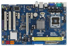
There are 3 PCI slots and 3 PCI Express slots on this motherboard. PCI slots: PCI slots are used to install expansion cards that have card to PCIE2 (PCIE x16 slot) and adjust the "Internal Graphics Mode Select" BIOS option to [Enabled], the onboard VGA will be enabled, and the primary screen will - ASRock G31DE | User Manual - Page 18
2.7 Jumpers Setup The illustration shows how jumpers are setup. When the jumper cap is placed on pins, the jumper is "Short". If no jumper cap is placed on pins, the jumper is "Open". The illustration shows a 3-pin jumper whose pin1 and pin2 are "Short" when jumper cap is placed on these 2 - ASRock G31DE | User Manual - Page 19
, see p.10 No. 7) PIN1 IDE1 connect the blue end connect the black end to the motherboard to the IDE devices 80-conductor ATA 66/100 cable Note: Please refer to the instruction of your IDE device vendor for the details. SATAII_1 SATAII_3 SATAII_2 SATAII_4 Serial ATAII Connectors (SATAII_1 - ASRock G31DE | User Manual - Page 20
panel, there are two USB 2.0 headers on this motherboard. Each USB 2.0 header can support two USB 2.0 ports. Infrared Module Header (5-pin supports Jack Sensing, but the panel wire on the chassis must support HDA to function correctly. Please follow the instruction in our manual and chassis manual - ASRock G31DE | User Manual - Page 21
D. MIC_RET and OUT_RET are for HD audio panel only. You don't need to connect them for AC'97 audio panel. E. Enter BIOS Setup Utility. Enter Advanced Settings, and then select Chipset Configuration. Set the Front Panel Control option from [Auto] to [Enabled]. F. Enter Windows system. Click the - ASRock G31DE | User Manual - Page 22
fan cable 2 +12V 3 CPU_FAN_SPEED to this connector and match 4 FAN_SPEED_CONTROL the black wire to the ground pin. Though this motherboard provides 4-Pin CPU fan (Quiet Fan) support, the 3-Pin CPU fan still can work successfully even without the fan speed control function. If you plan to - ASRock G31DE | User Manual - Page 23
HDMI_SPDIF Cable (Optional) C B A Please connect the black end (A) of HDMI_SPDIF cable to the HDMI_SPDIF header on the motherboard. Then connect the white end (B or C) of HDMI_SPDIF cable to the HDMI_SPDIF connector of HDMI VGA card. A. black end +5V SPDIFOUT GND blue black B. white - ASRock G31DE | User Manual - Page 24
motherboard with a HDMI_SPDIF header. This motherboard motherboard. For the proper installation of HDMI VGA card, please refer to the installation guide manual of HDMI VGA card vendor. Incorrect connection may cause permanent damage to this motherboard , the motherboard and the user manual for - ASRock G31DE | User Manual - Page 25
guide. Some default setting of SATAII hard disks may not be at SATAII mode, which operate with the best performance. In order to enable SATAII function, please follow the below instruction website for details: http://www.hitachigst.com/hdd/support/download.htm The above examples are just for your - ASRock G31DE | User Manual - Page 26
Connect one end of the SATA data cable to the motherboard's SATAII connector. STEP 4: Connect the other end of the SATA data cable to the SATA / SATAII hard disk. 2.12 Driver Installation Guide To install the drivers to your system, please insert the support CD to your optical drive first. Then, the - ASRock G31DE | User Manual - Page 27
motherboard stores the BIOS SETUP UTILITY. You may run the BIOS SETUP UTILITY when you start up the computer. Please press during the Power-On-Self-Test (POST) to enter the BIOS back on. Because the BIOS software is constantly being updated, the following BIOS setup screens and descriptions are - ASRock G31DE | User Manual - Page 28
System Overview System Time System Date [14:00:09] [Sat 02/07/2009] BIOS Version : G31DE P1.00 Processor Type : Intel(R) Core(TM) 2 Duo CPU E6850 @ 3.00GHz (64bit) Processor Speed : 3000MHz Microcode Update : 6FB/B6 Cache Size : 4096KB Total Memory DDRII1 DDRII2 : 2048MB : 1024MB/333MHz - ASRock G31DE | User Manual - Page 29
changes and exit setup?" Select [OK] to save the changes and exit the BIOS SETUP UTILITY. Load BIOS Defaults Load BIOS default values for all the setup questions. F9 key can be used for this overclocing may cause damage to your CPU and motherboard. It should be done at your own risk and expense. 29 - ASRock G31DE | User Manual - Page 30
Copyright 1985-2005, American Megatrends, Inc. Setting wrong values in this section may cause the system to malfunction. 3.4.1 CPU Configuration BIOS SETUP UTILITY Advanced CPU Configuration Overclock Mode CPU Frequency (MHz) PCIE Frequency (MHz) Boot Failure Guard Spread Spectrum Ratio Actual - ASRock G31DE | User Manual - Page 31
item appear to allow you changing the ratio value of this motherboard. If the CPU you adopt supports EIST (Intel (R) SpeedStep(tm) tech.), and you plan to support the Halt State (C1). The C1 state is supported through the native processor instructions HLT and MWAIT and requires no hardware support - ASRock G31DE | User Manual - Page 32
to [Enabled]. This item will be hidden if the current CPU does not support Intel (R) SpeedStep(tm) tech.. Please note that enabling this function may [Disable] if above issue occurs. 3.4.2 Chipset Configuration BIOS SETUP UTILITY Advanced Chipset Configuration Memory Remap Feature DRAM Frequency - ASRock G31DE | User Manual - Page 33
DRAM Frequency If [Auto] is selected, the motherboard will detect the memory module(s) inserted and assigns Dynamic Video Memory Technology) is an architecture that offers breakthrough perfor mance for the motherboard through efficient memory utilization. In Fixed mode, a fixed-size fragment of the - ASRock G31DE | User Manual - Page 34
® VistaTM OS because the driver will intelligently detect physical memory to select CPU Voltage. Configuration options: [Auto] and [Manual]. The default value of this feature is [Auto]. DRAM , please set this item to [Enabled]. Besides the BIOS option, you can also choose our Intelligent Energy Saver - ASRock G31DE | User Manual - Page 35
3.4.3 ACPI Configuration BIOS SETUP UTILITY Advanced ACPI the Suspend-to-RAM feature. Select [Auto] will enable this feature if the system supports it. Restore on AC/Power Loss This allows you to set the power state after you plan to use this motherboard to submit Windows® VistaTM certification. 35 - ASRock G31DE | User Manual - Page 36
3.4.4 IDE Configuration BIOS SETUP UTILITY Advanced IDE Configuration ATA/IDE 1, SATA 2, SATA 4], then SATAII_1, SATAII_3 will not work. Because Intel® ICH7 south bridge only supports four IDE devices under legacy OS (Windows NT), you have to choose [SATA 1, SATA 2, SATA instruction. 36 - ASRock G31DE | User Manual - Page 37
BIOS SETUP UTILITY Advanced Primary IDE Master Device Vendor Size LBA Mode Block Mode PIO Mode Async DMA Ultra DMA S.M.A.R.T. Type LBA/Large Mode Block (Multi-Sector Transfer) PIO Mode DMA Mode S.M.A.R.T. 32Bit Data Transfer :Hard Disk :ST340014A :40.0 GB :Supported :16Sectors :4 :MultiWord DMA-2 - ASRock G31DE | User Manual - Page 38
], [Enabled]. 32-Bit Data Transfer Use this item to enable 32-bit access to maximize the IDE hard disk data transfer rate. 3.4.5 PCIPnP Configuration BIOS SETUP UTILITY Advanced Advanced PCI / PnP Settings PCI Latency Timer PCI IDE BusMaster [32] [Enabled] Value in units of PCI clocks for PCI - ASRock G31DE | User Manual - Page 39
Address Parallel Port Mode EPP Version ECP Mode DMA Channel Parallel Port IRQ [Enabled] [3F8 / IRQ4] [Disabled] [378] [ECP + EPP] [1.9] [DMA3] [IRQ7] Allow BIOS to Enable or Disable Floppy Controller. +F1 F9 F10 ESC Select Screen Select Item Change Option General Help Load Defaults Save and Exit - ASRock G31DE | User Manual - Page 40
the IRQ for the parallel port. Configuration options: [IRQ5] and [IRQ7]. 3.4.8 USB Configuration BIOS SETUP UTILITY Advanced USB Configuration USB Controller USB 2.0 Support Legacy USB Support [Enabled] [Enabled] [BIOS Setup Only] To enable or disable the onboard USB controllers. +F1 F9 F10 - ASRock G31DE | User Manual - Page 41
the status of the hardware on your system, including the parameters of the CPU temperature, motherboard temperature, CPU fan speed, chassis fan speed, and the critical voltage. BIOS SETUP UTILITY Main Smart Advanced H/W Monitor Boot Security Exit Hardware Health Event Monitoring CPU Temperature - ASRock G31DE | User Manual - Page 42
this section, it will display the available devices on your system for you to configure the boot settings and the boot priority. BIOS SETUP UTILITY Main Smart Advanced H/W Monitor Boot Security Exit Boot Settings Boot Settings Configuration Configure Settings during System Boot. 1st Boot Device - ASRock G31DE | User Manual - Page 43
section, you may set or change the supervisor/user password for the system. For the user password, you may also clear it. BIOS SETUP UTILITY Main Smart Advanced H/W Monitor Boot Security Exit Security Settings Supervisor Password : Not Installed User Password : Not Installed Change Supervisor - ASRock G31DE | User Manual - Page 44
and exit setup?" Select [OK] to save the changes and exit the BIOS SETUP UTILITY. Discard Changes and Exit When you select this option, it message, "Discard changes and exit setup?" Select [OK] to exit the BIOS SETUP UTILITY without saving any changes. Discard Changes When you select this option - ASRock G31DE | User Manual - Page 45
install the necessary drivers to activate the devices. 4.2.3 Utilities Menu The Utilities Menu shows the applications software that the motherboard supports. Click on a specific item then follow the installation wizard to install it. 4.2.4 Contact Information If you need to contact ASRock or want to
-
 1
1 -
 2
2 -
 3
3 -
 4
4 -
 5
5 -
 6
6 -
 7
7 -
8
-
9
-
10
-
11
-
12
-
13
-
14
-
15
-
16
-
17
-
18
-
19
-
20
-
21
-
22
-
23
-
24
-
25
-
26
-
27
-
28
-
29
-
30
-
31
-
32
-
33
-
34
-
35
-
36
-
37
-
38
-
39
-
40
-
41
-
42
-
43
-
44
-
45
 |
 |

1
G31DE
User Manual
Version 1.0
Published February 2009
Copyright©2009 ASRock INC. All rights reserved.