ASRock G31DE Quick Installation Guide
ASRock G31DE Manual
 |
View all ASRock G31DE manuals
Add to My Manuals
Save this manual to your list of manuals |
ASRock G31DE manual content summary:
- ASRock G31DE | Quick Installation Guide - Page 1
for backup purpose, without written consent of ASRock Inc. Products and corporate names appearing in this guide may or may not be registered trademarks or ASRock Website: http://www.asrock.com Published February 2009 Copyright©2009 ASRock INC. All rights reserved. 1 ASRock G31DE Motherboard - ASRock G31DE | Quick Installation Guide - Page 2
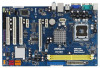
Motherboard Layout English 1 PS2_USB_PWR1 Jumper 17 Chassis Fan Connector (CHA_FAN1) 2 ATX 12V Connector (ATX12V1) 18 USB 2.0 Header (USB6_7, Blue) 3 775-Pin CPU Socket 19 USB 2.0 Header ( Header (PANEL1, Orange) 31 CPU Fan Connector (CPU_FAN1) 16 BIOS SPI Chip 2 ASRock G31DE Motherboard - ASRock G31DE | Quick Installation Guide - Page 3
"Stereo". Click "Device advanced settings", choose "Make front and rear output devices playbacks two different audio streams simultaneously", and click "ok". Then reboot your system. 3 ASRock G31DE Motherboard English - ASRock G31DE | Quick Installation Guide - Page 4
introduction of the motherboard and step-by-step installation guide. More detailed information of the motherboard can be found in the user manual presented in the Support CD. Because the motherboard specifications and the BIOS software might be updated, the content of this manual will be subject - ASRock G31DE | Quick Installation Guide - Page 5
Supports Wake-On-LAN I/O Panel - 1 x PS/2 Mouse Port - 1 x PS/2 Keyboard Port - 1 x Serial Port: COM1 - 1 x VGA Port - 4 x Ready-to-Use USB 2.0 Ports - 1 x RJ-45 LAN Port with LED (ACT/LINK LED and SPEED LED) - HD Audio Jack: Line in / Front Speaker / Microphone English 5 ASRock G31DE Motherboard - ASRock G31DE | Quick Installation Guide - Page 6
AMI BIOS - AMI Legal BIOS - Supports "Plug and Play" - ACPI 1.1 Compliance Wake Up Events - Supports jumperfree - SMBIOS 2.3.1 Support - CPU, VCCM Voltage Multi-adjustment - Supports Smart BIOS Support CD - Drivers, Utilities, AntiVirus Software (Trial Version) Unique Feature - ASRock OC - ASRock G31DE | Quick Installation Guide - Page 7
frequency will also be overclocked to 120MHz. 2. About the setting of "Hyper Threading Technology", please check page 32 of "User Manual" in the support CD. 3. This motherboard supports Untied Overclocking Technology. Please read "Untied Overclocking Technology" on page 19 for details. 4. This - ASRock G31DE | Quick Installation Guide - Page 8
operation procedures of ASRock OC Tuner. ASRock website: http://www.asrock.com 11. Featuring Saver. ASRock website: http://www.asrock.com 12. Although this motherboard offers stepless the system, please check if the CPU fan on the motherboard functions properly and unplug the power cord, then plug it - ASRock G31DE | Quick Installation Guide - Page 9
Before you insert the 775-LAND CPU into the socket, please check if the CPU surface is unclean or if there is any bent pin on the socket. Do not force to insert the CPU into the socket if above situation is found. Otherwise, the CPU will be seriously damaged. 9 ASRock G31DE Motherboard English - ASRock G31DE | Quick Installation Guide - Page 10
key notch Pin1 alignment key alignment key 775-LAND CPU 775-Pin Socket For proper inserting, please ensure support the load plate edge, engage PnP cap with right hand thumb and peel the cap from the socket while pressing on center of PnP cap to assist in removal. 10 ASRock G31DE Motherboard - ASRock G31DE | Quick Installation Guide - Page 11
cap must be placed if returning the motherboard for after service. Step 4. Close the socket: instruction manuals of your CPU fan and heatsink. Below is an example to illustrate the installation of the heatsink for 775 motherboard (CPU_FAN1, see page 2, No. 31). Align fasteners with the motherboard - ASRock G31DE | Quick Installation Guide - Page 12
G31DE motherboard provides two 240-pin DDR2 (Double Data Rate 2) DIMM slots, and supports a DDR memory module into DDR2 slot; otherwise, this motherboard and DIMM may be damaged. 2. If you install orientation. It will cause permanent damage to the motherboard and the DIMM if you force the DIMM into - ASRock G31DE | Quick Installation Guide - Page 13
-on PCI Express VGA card to PCIE2 (PCIE x16 slot) and adjust the "Internal Graphics Mode Select" BIOS option to [Enabled], the onboard VGA will be enabled, and the primary screen will be onboard VGA. Installing Step 4. Fasten the card to the chassis with screws. 13 ASRock G31DE Motherboard English - ASRock G31DE | Quick Installation Guide - Page 14
unplug the power cord from the power supply. After waiting for 15 seconds, use a jumper cap to short 2 pins on CLRCMOS1 for 5 seconds. English 14 ASRock G31DE Motherboard - ASRock G31DE | Quick Installation Guide - Page 15
instruction of your IDE device vendor for the details. Serial ATAII Connectors (SATAII_1: see p.2, No. 13) (SATAII_2: see p.2, No. 12) (SATAII_3: see p.2, No. 10) (SATAII_4: see p.2, No. 11) These Serial ATAII (SATAII) connectors support connector of the power supply. 15 ASRock G31DE Motherboard - ASRock G31DE | Quick Installation Guide - Page 16
chassis manual to install your system. 2. If you use AC'97 audio panel, please install it to the front panel audio header as below: A. Connect Mic_IN (MIC) to MIC2_L. B. Connect Audio_R (RIN) to OUT2_R and Audio_L (LIN) to OUT2_L. C. Connect Ground (GND) to Ground (GND). 16 ASRock G31DE Motherboard - ASRock G31DE | Quick Installation Guide - Page 17
for HD audio panel only. You don't need to connect them for AC'97 audio panel. E. Enter BIOS Setup Utility. Enter Advanced Settings, and then select Chipset Configuration. Set the Front Panel Control option from [Auto match the black wire to the ground pin. English 17 ASRock G31DE Motherboard - ASRock G31DE | Quick Installation Guide - Page 18
cable to this connector and match the black wire to the ground pin. Though this motherboard provides 4-Pin CPU fan (Quiet Fan) support, the 3-Pin CPU fan still can work successfully even without the fan speed control function of HDMI VGA card to this header. English 18 ASRock G31DE Motherboard - ASRock G31DE | Quick Installation Guide - Page 19
motherboard. Then connect the white end (B or C) of HDMI_SPDIF cable to the HDMI_SPDIF connector of HDMI VGA card. B. white end (2-pin) C. white end (3-pin) 2.7 Driver Installation Guide To install the drivers to your system, please insert the support . English 19 ASRock G31DE Motherboard - ASRock G31DE | Quick Installation Guide - Page 20
detailed information about BIOS Setup, please refer to the User Manual (PDF file) contained in the Support CD. 4. Software Support CD information This motherboard supports various Microsoft® Windows EXE" from the BIN folder in the Support CD to display the menus. 20 ASRock G31DE Motherboard English - ASRock G31DE | Quick Installation Guide - Page 21
zu Ihrem Modell benötigen, besuchen Sie bitte unsere Webseite: www.asrock.com/support/index.asp 1.1 Kartoninhalt ASRock G31DE Motherboard (ATX-Formfaktor: 30.5 cm x 19.1 cm; 12.0 Zoll x 7.5 Zoll) ASRock G31DE Schnellinstallationsanleitung ASRock G31DE_ Support-CD Ein 80-adriges Ultra-ATA 66/100 IDE - ASRock G31DE | Quick Installation Guide - Page 22
: 30.5 cm x 19.1 cm; 12.0 Zoll x 7.5 Zoll - LGA 775 für Intel® CoreTM 2 Extreme / CoreTM 2 Quad / CoreTM 2 Duo / - Unterstützt EM64T-CPU - Northbridge: Intel® G31 - Southbridge: Intel® ICH7 - Unterstützung von COM 1 - 1 x VGA Port - 4 x Ready-to-Use USB 2.0 Ports ASRock G31DE Motherboard Deutsch - ASRock G31DE | Quick Installation Guide - Page 23
Anschlüsse BIOS Support-CD Einzigartige Eigenschaft Hardware Monitor Betriebssysteme - 1 x RJ-45 LAN Port mit LED (ACT/LINK LED und SPEED LED) - Audioanschlüsse , +5V, +3.3V, Vcore - Unterstützt Microsoft® Windows® 2000 / XP / XP 64-Bit / VistaTM / VistaTM 64-Bit 23 ASRock G31DE Motherboard Deutsch - ASRock G31DE | Quick Installation Guide - Page 24
Website: http://www.asrock.com WARNUNG Beachten Sie bitte, dass Overclocking, einschließlich der Einstellung im BIOS, Anwenden der 32 des auf der Support-CD enthaltenen Benutzerhandbuches beschrieben. 3. Dieses Motherboard unterstützt die Untied änkung nicht. 24 ASRock G31DE Motherboard Deutsch - ASRock G31DE | Quick Installation Guide - Page 25
" auf der Support-CD, um Ihre 10. Es ist ein benutzerfreundlicher ASRock Übertaktenswerkzeug, das erlaubt, dass Sie ASRock OC Tuner. ASRock-Website: http://www.asrock ASRock-Website: http://www.asrock.com 12. Obwohl dieses Motherboard der CPU-Lüfter am Motherboard richtig funktioniert, und stecken - ASRock G31DE | Quick Installation Guide - Page 26
Default-Werte wiederherzustellen, schalten Sie den Computer aus, ziehen Sie den Netzstecker und überbrücken Sie 2-pin von CLRCMOS1 mithilfe des Jumpers für 5 Sekunden. Deutsch 26 ASRock G31DE Motherboard - ASRock G31DE | Quick Installation Guide - Page 27
diese Header und Anschlüsse. Wenn Sie Jumperkappen auf Header und Anschlüsse setzen, wird das Motherboard unreparierbar beschädigt! Anschluss für das Floppy-Laufwerk (33-Pin FLOPPY1) (siehe S.2 - am Mainboard verbinden. SATAII_1 SATAII_3 SATAII_2 SATAII_4 Deutsch 27 ASRock G31DE Motherboard - ASRock G31DE | Quick Installation Guide - Page 28
üblichen USB 2.0-Ports an den I/O-Anschlüssen befinden sich zwei USB 2.0-Anschlussleisten am Motherboard. Pro USB 2.0Anschlussleiste werden zwei USB 2.0-Ports unterstützt. Infrarot-Modul-Header (5- ROM, TV-Tuner oder MPEG-Karten mit Ihrem System zu verbinden. 28 ASRock G31DE Motherboard Deutsch - ASRock G31DE | Quick Installation Guide - Page 29
ssen nicht an die AC'97-Audioleiste angeschlossen werden. E. Rufen Sie das BIOS-Setup-Dienstprogramm auf. Wechseln Sie zu Erweiterte Einstellungen und wählen Sie Chipset- (Standardgerät einstellen), um das vorderseitige Mikrofon als StandardAufnahmegerät zu übernehmen. 29 ASRock G31DE Motherboard - ASRock G31DE | Quick Installation Guide - Page 30
No. 6) 12 24 Verbinden Sie die ATXStromversorgung mit diesem Header. 1 13 Obwohl dieses Motherboard einen 24-pol. ATX-Stromanschluss 12 24 bietet, kann es auch mit einem modifizierten traditionellen ein. Installation eines 20-pol. ATX-Netzteils 1 13 30 ASRock G31DE Motherboard Deutsch - ASRock G31DE | Quick Installation Guide - Page 31
-Anschluss der HDMI-VGA-Karte mit diesem Anschluss. Bitte verbinden Sie das schwarze Ende (A) des HDMI_SPDIF-Kabels mit dem HDMI_SPDIF-Anschluss am Motherboard. Schließen Sie dann das weiße Ende (B oder C) des HDMI_SPDIF-Kabels an den HDMI_SPDIF-Anschluss der HDMI-VGA-Karte an. A. Schwarzes Ende - ASRock G31DE | Quick Installation Guide - Page 32
und die vorab festgelegten Optionen auswählen können. Für detaillierte Informationen zum BIOS-Setup, siehe bitte das Benutzerhandbuch (PDF Datei) auf der Support CD. 3. Software Support CD information Dieses Motherboard unterstützt eine Reiche von Microsoft® Windows® Betriebssystemen: 2000 / XP / XP - ASRock G31DE | Quick Installation Guide - Page 33
particulières au modèle que vous utilisez. www.asrock.com/support/index.asp 1.1 Contenu du paquet Carte mère ASRock G31DE (Facteur de forme ATX : 12.0 pouces x 7.5 pouces, 30.5 cm x 19.1 cm) Guide d'installation rapide ASRock G31DE CD de soutien ASRock G31DE Un câble ruban IDE Ultra ATA 66/100 80 - ASRock G31DE | Quick Installation Guide - Page 34
: 12.0 pouces x 7.5 pouces, 30.5 cm x 19.1 cm - LGA 775 pour Intel® CoreTM 2 Extreme / CoreTM 2 Quad / CoreTM 2 Duo / Support du Wake-On-LAN I/O Panel - 1 x port souris PS/2 - 1 x port clavier PS/2 - 1 x port série: COM 1 - 1 x port VGA - 4 x ports USB 2.0 par défaut 34 ASRock G31DE Motherboard - ASRock G31DE | Quick Installation Guide - Page 35
Support SMBIOS 2.3.1 - CPU, VCCM Tension Multi-ajustement - Prise en charge du Smart BIOS CD d'assistance - Pilotes, utilitaires, logiciel anti-virus (Version d'essai) Caractéristique - Tuner ASRock unité centrale - Monitoring de la tension: +12V, +5V, +3.3V, Vcore 35 ASRock G31DE Motherboard - ASRock G31DE | Quick Installation Guide - Page 36
compris ajuster les réglages du BIOS, appliquer la technologie Untied Overclocking plus d'informations. 4. Cette carte mère supporte la Technologie de Mémoire à Canal Double. Double, assurez-vous de bien lire le guide d'installation des modules mémoire en page ASRock G31DE Motherboard Français - ASRock G31DE | Quick Installation Guide - Page 37
SATAII au connecteur SATAII, veuillez lire le Guide « Installation du disque dur SATAII » à la page 25 du « Manuel de l'utilisateur » qui se trouve sur le CD de support pour régler votre lecteur de disque dur le CPU le dissipateur lors de l'installation du PC. 37 ASRock G31DE Motherboard Français - ASRock G31DE | Quick Installation Guide - Page 38
. Puis placez un cavalier sur les pins CLRCMOS1 pendant 5 secondes. N'oubliez pas de retirer le cavalier avant après avoir restauré le CMOS. Français 38 ASRock G31DE Motherboard - ASRock G31DE | Quick Installation Guide - Page 39
re connecteur noir vers le disque dur Câble ATA 66/100 80 conducteurs Note: Veuillez vous reporter aux instructions du fabricant de votre IDE périphérique pour les détails. Connecteurs Série ATAII (SATAII_1: voir SATA / SATAIIou au connecteur SATAII sur la carte mère. 39 ASRock G31DE Motherboard - ASRock G31DE | Quick Installation Guide - Page 40
p.2 No. 20) Embase de port d'impression (LPT1 25 broches) (voir p.2 No. 21) Cet en-tête supporte un module infrarouge optionnel de transfert et de réception sans fil. AIl s'agit d'une interface pour le câble du ROM, DVD-ROM, un tuner TV ou une carte MPEG. 40 ASRock G31DE Motherboard Français - ASRock G31DE | Quick Installation Guide - Page 41
en charge le HDA pour fonctionner correctement. Veuillez suivre les instructions dans notre manuel et le manuel de châssis afin audio AC'97. E. Entrer dans l'utilitaire de configuration du BIOS. Saisir les Paramètres avancés puis sélectionner Configuration du jeu ASRock G31DE Motherboard Français - ASRock G31DE | Quick Installation Guide - Page 42
de ventilateur d'UC sur ce connecteur et brancher le fil ien que cette carte mère offre un support de (Ventilateur silencieux) ventilateur de CPU à 4 broches , le ventilateur de CPU à 3 broches 1 et 13. 20-Installation de l'alimentation électrique ATX 1 13 42 ASRock G31DE Motherboard Français - ASRock G31DE | Quick Installation Guide - Page 43
ensuite l'extrémité blanche (B ou C) du câble HDMI_SPDIF au connecteur HDMI_SPDIF de la carte VGA HDMI. B. extrémité blanche (2 briches) C. extrémité blanche (3 briches) 43 ASRock G31DE Motherboard Français - ASRock G31DE | Quick Installation Guide - Page 44
-Test) pour entrer dans le BIOS; sinon, le POST continue ses tests de routine. Si vous désirez entrer dans le BIOS BIOS, veuillez consulter le Guide de l'utilisateur (fichier PDF) dans le CD technique. 3. Informations sur le CD de support Cette carte mère supporte ASRock G31DE Motherboard Français - ASRock G31DE | Quick Installation Guide - Page 45
specifiche sul modello che si sta usando. www.asrock.com/support/index.asp 1.1 Contenuto della confezione Scheda madre ASRock G31DE (ATX Form Factor: 12.0-in x 7.5-in, 30.5 cm x 19.1 cm) Guida di installazione rapida ASRock G31DE CD di supporto ASRock G31DE Un cavo IDE 80-pin Ultra ATA 66/100 - ASRock G31DE | Quick Installation Guide - Page 46
Factor: 12.0-in x 7.5-in, 30.5 cm x 19.1 cm - LGA 775 per Intel® CoreTM 2 Extreme / CoreTM 2 Quad / CoreTM 2 Duo / 3) - Supporto CPU EM64T - Northbridge: Intel® G31 - Southbridge: Intel® ICH7 - Supporto tecnologia Dual Audio Jack: Line In / Line Out / Microfono ASRock G31DE Motherboard Italiano - ASRock G31DE | Quick Installation Guide - Page 47
VCCM - Smart BIOS supportato CD di - Driver, utilità, software antivirus (Versione dimostrativa) supporto Caratteris- - Sintonizzatore ASRock OC (vedi ATTENZIONE * Per ulteriori informazioni, prego visitare il nostro sito internet: http://www.asrock.com Italiano 47 ASRock G31DE Motherboard - ASRock G31DE | Quick Installation Guide - Page 48
, come anche la regolazione delle impostazioni del BIOS, l'applicazione della tecnologia Untied Overclocking Technology, oppure "Tecnologia Hyper-Threading", per favore controllare pagina 32 del Manuale dell'utente all'interno del CD di supporto. 3. Questa Italiano 48 ASRock G31DE Motherboard - ASRock G31DE | Quick Installation Guide - Page 49
SATAII, leggere la "Guida per la configurazione del disco rigido SATAII" a pagina 25 del "Manuale utente" nel CD in dotazione in modo da poter predisporre il disco rigido SATAII per la modalit il processore e il dissipatore quando si installa il sistema. 49 ASRock G31DE Motherboard Italiano - ASRock G31DE | Quick Installation Guide - Page 50
. Per pulire I parametri di sistema e resettare ai parametri di default, spegnere il computer e scollegare l'alimentatore, poi collegare il jumper sul CLRCMOS1 per 5 secondi. Italiano 50 ASRock G31DE Motherboard - ASRock G31DE | Quick Installation Guide - Page 51
Serial ATA (SATA) (Opzionale) Entrambe le estremità del cavo dati SATA possono collegarsi all'hard disk SATA / SATAII o al connettore SATAII sulla scheda madre. 51 ASRock G31DE Motherboard - ASRock G31DE | Quick Installation Guide - Page 52
) (CD1: vedi p.2 Nr. 25) Permettono di ricevere input stereo audio da fonti di CD1 suono come CD-ROM, DVD - ROM,TV tuner, o schede MPEG. 52 ASRock G31DE Motherboard Italiano - ASRock G31DE | Quick Installation Guide - Page 53
in modo corretto. Attenersi alle istruzioni del nostro manuale e del manuale del telaio per installare il sistema. 2. Se AC'97. E. Entrare nel programma di impostazione BIOS. Entrare su Impostazioni avanzate, quindi selezionare Configurazione chipset . 53 ASRock G31DE Motherboard Italiano - ASRock G31DE | Quick Installation Guide - Page 54
ATX a 20 pin. Per usare l'alimentatore ATX a 20 pin, collegare l'alimentatore con il Pin 1 e il Pin 13. Installazione dell'alimentatore ATX a 20 pin 1 13 54 ASRock G31DE Motherboard Italiano - ASRock G31DE | Quick Installation Guide - Page 55
scheda madre. Quindi collegare l'estremità bianca (B o C) del cavo HDMI_SPDIF al connettore HDMI_SPDIF della scheda HDMI VGA. A. estremità nera B. estremità bianca (2 pin) C. estremità bianca (3 pin) 55 ASRock G31DE Motherboard Italiano - ASRock G31DE | Quick Installation Guide - Page 56
test di routine. Per entrare il BIOS Setup dopo il POST, riavvia il sistema premendo + + , o premi il tasto di reset sullo chassis del sistema. Per informazioni più dettagliate circa il Setup del BIOS, fare riferimento al Manuale dell'Utente (PDF ASRock G31DE Motherboard Italiano - ASRock G31DE | Quick Installation Guide - Page 57
el número de modelo específico de su placa. www.asrock.com/support/index.asp 1.1 Contenido de la caja Placa base ASRock G31DE (Factor forma ATX: 30,5 cm x 19,1 cm, 12,0" x 7,5") Guía de instalación rápida de ASRock G31DE CD de soporte de ASRock G31DE Una cinta de datos IDE de conducción 80 Ultra ATA - ASRock G31DE | Quick Installation Guide - Page 58
forma ATX: 30,5 cm x 19,1 cm, 12,0" x 7,5" - LGA 775 para Intel® CoreTM 2 Extreme / CoreTM 2 Quad / CoreTM 2 Duo / (vea ATENCIÓN 3) - Admite CPU EM64T - North Bridge: Intel® G31 - South Bridge: Intel® ICH7 - Soporte de Tecnología de Memoria de / Line Out / Micrófono ASRock G31DE Motherboard Español - ASRock G31DE | Quick Installation Guide - Page 59
- 2 x Conector USB 2.0 (compatible con 4 puertos USB 2.0) (vea ATENCIÓN 9) - 4Mb AMI BIOS - AMI legal BIOS - Soporta "Plug and Play" - ACPI 1.1 compliance wake up events - Soporta "jumper free setup" para procesador - Monitor de Voltaje: +12V, +5V, +3.3V, Vcore Español 59 ASRock G31DE Motherboard - ASRock G31DE | Quick Installation Guide - Page 60
de aumento de la velocidad del reloj, incluido el ajuste del BIOS, aplicando la tecnología de aumento de velocidad liberada o utilizando sobreacelerará a 120MHz. 2. Por favor consulte página 32 del Manual del Usuario en el soporte CD sobre la configuración de Español 60 ASRock G31DE Motherboard - ASRock G31DE | Quick Installation Guide - Page 61
SATAII, consulte la sección "Guía de instalación de discos duros SATAII" en la página 25 del "Manual de usuario" que se incluye en el CD de soporte para configurar su disco duro SATAII en modo SATAII. el disipador de calor cuando usted instala el sistema de PC. 61 ASRock G31DE Motherboard Español - ASRock G31DE | Quick Installation Guide - Page 62
y desconecte el cable de la fuente de electricidad, ponga en cortocircuito los pins de CLRCMOS1 por más que 5 segundos usando un jumper cap. Español 62 ASRock G31DE Motherboard - ASRock G31DE | Quick Installation Guide - Page 63
) (Opcional) Ambos extremos del cable pueden conectarse al disco duro SATA / SATAII o la conexión de la placa base. SATAII_1 SATAII_3 SATAII_2 SATAII_4 Español 63 ASRock G31DE Motherboard - ASRock G31DE | Quick Installation Guide - Page 64
audio interno (4-pin CD1) (CD1: vea p. 2, N. 25) Permite recepción de input audio de fuente sónica como CDCD1 ROM, DVD-ROM, TV tuner, o tarjeta MPEG. 64 ASRock G31DE Motherboard Español - ASRock G31DE | Quick Installation Guide - Page 65
correctamente. Por favor, siga las instrucciones en nuestro manual y en el manual de chasis para instalar su sistema. 2. Si utiliza AC'97. E. Entre en la Utilidad de configuración del BIOS Entre en Configuración avanzada y, a continuación, seleccione Configuración ASRock G31DE Motherboard Español - ASRock G31DE | Quick Installation Guide - Page 66
20 pins, por favor, conecte su fuente de alimentación usando los Pins 1 y 13. Instalación de una Fuente de Alimentación ATX de 20 Pins 1 13 66 ASRock G31DE Motherboard Español - ASRock G31DE | Quick Installation Guide - Page 67
después el extremo blanco (B o C) del cable HDMI_SPDIF en el conector HDMI_SPDIF de la tarjeta VGA HDMI. A. Extremo negro B. Extremo blanco (2 patillas) C. Extremo blanco (3 patillas) 67 ASRock G31DE Motherboard Español - ASRock G31DE | Quick Installation Guide - Page 68
la Utilidad de configuración de la BIOS, consulte el Manual del usuario (archivo PDF), que se encuentra en el CD de soporte. 3.Información de Software Support CD Esta placa-base soporta diversos doble-pulse en el archivo "ASSETUP.EXE" para iniciar la instalación. 68 ASRock G31DE Motherboard Español - ASRock G31DE | Quick Installation Guide - Page 69
81 ASRock G31DE Motherboard - ASRock G31DE | Quick Installation Guide - Page 70
® ® / ® ® ® ® ® ® 82 ASRock G31DE Motherboard - ASRock G31DE | Quick Installation Guide - Page 71
® 83 ASRock G31DE Motherboard - ASRock G31DE | Quick Installation Guide - Page 72
" " ® " ® ® ® " " ® " 84 ASRock G31DE Motherboard - ASRock G31DE | Quick Installation Guide - Page 73
® "" "" "" "" 85 ASRock G31DE Motherboard - ASRock G31DE | Quick Installation Guide - Page 74
SATAII_1 SATAII_3 SATAII_2 SATAII_4 86 ASRock G31DE Motherboard - ASRock G31DE | Quick Installation Guide - Page 75
CD1 87 ASRock G31DE Motherboard - ASRock G31DE | Quick Installation Guide - Page 76
® ® ® ® " " " " " ® " " " " "" " 88 ASRock G31DE Motherboard - ASRock G31DE | Quick Installation Guide - Page 77
1 2 3 4 12 24 1 13 5 1 8 4 12 24 1 13 5 1 8 4 89 ASRock G31DE Motherboard - ASRock G31DE | Quick Installation Guide - Page 78
C B A " " " " \\ 90 ASRock G31DE Motherboard - ASRock G31DE | Quick Installation Guide - Page 79
91 ASRock G31DE Motherboard - ASRock G31DE | Quick Installation Guide - Page 80
® ® ® ® ® ® ® ® 92 ASRock G31DE Motherboard - ASRock G31DE | Quick Installation Guide - Page 81
® ® ® 93 ASRock G31DE Motherboard - ASRock G31DE | Quick Installation Guide - Page 82
" " ® ® ® ® ® 94 ASRock G31DE Motherboard - ASRock G31DE | Quick Installation Guide - Page 83
® ® TM TM ® 95 ASRock G31DE Motherboard - ASRock G31DE | Quick Installation Guide - Page 84
96 ASRock G31DE Motherboard - ASRock G31DE | Quick Installation Guide - Page 85
SATAII_1 SATAII_3 SATAII_2 SATAII_4 97 ASRock G31DE Motherboard - ASRock G31DE | Quick Installation Guide - Page 86
CD1 98 ASRock G31DE Motherboard - ASRock G31DE | Quick Installation Guide - Page 87
99 ASRock G31DE Motherboard - ASRock G31DE | Quick Installation Guide - Page 88
100 1 2 3 4 12 24 1 13 5 1 8 4 12 24 1 13 ASRock G31DE Motherboard 5 1 8 4 - ASRock G31DE | Quick Installation Guide - Page 89
C B A 12 24 1 13 5 1 8 4 ® ® TM TM ASRock G31DE Motherboard 101 - ASRock G31DE | Quick Installation Guide - Page 90
102 ASRock G31DE Motherboard - ASRock G31DE | Quick Installation Guide - Page 91
® ® ® ® ® ® ® ® ASRock G31DE Motherboard 103 - ASRock G31DE | Quick Installation Guide - Page 92
104 ® ® ASRock G31DE Motherboard - ASRock G31DE | Quick Installation Guide - Page 93
® ® ® ® ® ® ® ASRock G31DE Motherboard 105 - ASRock G31DE | Quick Installation Guide - Page 94
106 ASRock G31DE Motherboard - ASRock G31DE | Quick Installation Guide - Page 95
SATAII_1 SATAII_3 SATAII_2 SATAII_4 ASRock G31DE Motherboard 107 - ASRock G31DE | Quick Installation Guide - Page 96
CD1 108 ASRock G31DE Motherboard - ASRock G31DE | Quick Installation Guide - Page 97
® ® ® ® 1 2 3 4 ASRock G31DE Motherboard 109 - ASRock G31DE | Quick Installation Guide - Page 98
12 24 1 13 5 1 8 4 12 24 1 13 5 1 8 4 110 ASRock G31DE Motherboard - ASRock G31DE | Quick Installation Guide - Page 99
12 24 1 13 5 1 8 4 C B A ® ® ASRock G31DE Motherboard 111 - ASRock G31DE | Quick Installation Guide - Page 100
X O O O X O O O O: X: O O O O 112 ASRock G31DE Motherboard
-
 1
1 -
 2
2 -
 3
3 -
 4
4 -
 5
5 -
 6
6 -
 7
7 -
8
-
9
-
10
-
11
-
12
-
13
-
14
-
15
-
16
-
17
-
18
-
19
-
20
-
21
-
22
-
23
-
24
-
25
-
26
-
27
-
28
-
29
-
30
-
31
-
32
-
33
-
34
-
35
-
36
-
37
-
38
-
39
-
40
-
41
-
42
-
43
-
44
-
45
-
46
-
47
-
48
-
49
-
50
-
51
-
52
-
53
-
54
-
55
-
56
-
57
-
58
-
59
-
60
-
61
-
62
-
63
-
64
-
65
-
66
-
67
-
68
-
69
-
70
-
71
-
72
-
73
-
74
-
75
-
76
-
77
-
78
-
79
-
80
-
81
-
82
-
83
-
84
-
85
-
86
-
87
-
88
-
89
-
90
-
91
-
92
-
93
-
94
-
95
-
96
-
97
-
98
-
99
-
100
 |
 |

1
ASRock
G31DE
Motherboard
English
English
English
English
English
Copyright Notice:
Copyright Notice:
Copyright Notice:
Copyright Notice:
Copyright Notice:
No part of this installation guide may be reproduced, transcribed, transmitted, or trans-
lated in any language, in any form or by any means, except duplication of documen-
tation by the purchaser for backup purpose, without written consent of ASRock Inc.
Products and corporate names appearing in this guide may or may not be registered
trademarks or copyrights of their respective companies, and are used only for identifica-
tion or explanation and to the owners’ benefit, without intent to infringe.
Disclaimer:
Disclaimer:
Disclaimer:
Disclaimer:
Disclaimer:
Specifications and information contained in this guide are furnished for informational
use only and subject to change without notice, and should not be constructed as a
commitment by ASRock. ASRock assumes no responsibility for any errors or omissions
that may appear in this guide.
With respect to the contents of this guide, ASRock does not provide warranty of any kind,
either expressed or implied, including but not limited to the implied warranties or
conditions of merchantability or fitness for a particular purpose. In no event shall
ASRock, its directors, officers, employees, or agents be liable for any indirect, special,
incidental, or consequential damages (including damages for loss of profits, loss of
business, loss of data, interruption of business and the like), even if ASRock has been
advised of the possibility of such damages arising from any defect or error in the guide
or product.
This device complies with Part 15 of the FCC Rules. Operation is subject to the
following two conditions:
(1)
this device may not cause harmful interference, and
(2)
this device must accept any interference received, including interference that
may cause undesired operation.
Published February 2009
Copyright
©
2009 ASRock INC. All rights reserved.
CALIFORNIA, USA ONLY
The Lithium battery adopted on this motherboard contains Perchlorate, a toxic
substance controlled in Perchlorate Best Management Practices (BMP) regulations
passed by the California Legislature. When you discard the Lithium battery in
California, USA, please follow the related regulations in advance.
“Perchlorate Material-special handling may apply, see
www
.dtsc.ca.gov/hazardouswa
ste/perchlorate”
ASRock Website: http://www.asrock.com