ASRock G31M-GS R2.0 User Manual
ASRock G31M-GS R2.0 Manual
 |
View all ASRock G31M-GS R2.0 manuals
Add to My Manuals
Save this manual to your list of manuals |
ASRock G31M-GS R2.0 manual content summary:
- ASRock G31M-GS R2.0 | User Manual - Page 1
G31M-GS / G31M-S User Manual Version 2.0 Published June 2009 Copyright©2009 ASRock INC. All rights reserved. 1 - ASRock G31M-GS R2.0 | User Manual - Page 2
any form or by any means, except duplication of documentation by the purchaser for backup purpose, without written consent of ASRock Inc. Products and corporate names appearing in this manual may or may not be registered trademarks or copyrights of their respective companies, and are used only for - ASRock G31M-GS R2.0 | User Manual - Page 3
Contents 5 1.2 Specifications 6 1.3 Motherboard Layout 10 1.4 I/O Panel (G31M-GS 11 1.5 I/O Panel (G31M-S 12 2 Installation 13 2.1 Screw Holes 13 2.2 Pre-installation Precautions 13 2.3 CPU Installation 14 2.4 Installation of Heatsink and CPU fan 16 2.5 Installation of Memory Modules (DIMM - ASRock G31M-GS R2.0 | User Manual - Page 4
3.7 Security Screen 44 3.8 Exit Screen 45 4 Software Support 46 4.1 Install Operating System 46 4.2 Support CD Information 46 4.2.1 Running Support CD 46 4.2.2 Drivers Menu 46 4.2.3 Utilities Menu 46 4.2.4 Contact Information 46 4 - ASRock G31M-GS R2.0 | User Manual - Page 5
about the model you are using. www.asrock.com/support/index.asp 1.1 Package Contents ASRock G31M-GS / G31M-S Motherboard (Micro ATX Form Factor: 9.6-in x 7.2-in, 24.4 cm x 18.3 cm) ASRock G31M-GS / G31M-S Quick Installation Guide ASRock G31M-GS / G31M-S Support CD One 80-conductor Ultra ATA 66/100 - ASRock G31M-GS R2.0 | User Manual - Page 6
Platform CPU Chipset Memory Expansion Slot Graphics Audio LAN Rear Panel I/O 6 - Micro ATX Form Factor: 9.6-in x 7.2-in, 24.4 cm x 18.3 cm - LGA 775 for Intel® CoreTM 2 Extreme / CoreTM 2 Quad / CoreTM 2 Duo / Pentium® Dual Core / Celeron® Dual Core / Celeron®, supporting Penryn Quad - ASRock G31M-GS R2.0 | User Manual - Page 7
connector - 1 x Print port header - CPU/Chassis FAN connector - 24 pin ATX power connector - 4 pin 12V power connector - Front panel audio connector - 2 x USB 2.0 headers (support 4 USB 2.0 ports) (see CAUTION 9) BIOS Feature - 4Mb AMI BIOS - AMI Legal BIOS - Supports "Plug and Play - ASRock G31M-GS R2.0 | User Manual - Page 8
motherboard supports Untied Overclocking Technology. Please read "Untied Overclocking Technology" on page 26 for details. 4. This motherboard supports Dual Channel Memory Technology. Before you implement Dual Channel Memory Technology, make sure to read the installation guide of memory modules - ASRock G31M-GS R2.0 | User Manual - Page 9
of Intelligent Energy Saver. ASRock website: http://www.asrock.com 12. ASRock Instant Flash is a BIOS flash utility embedded in Flash ROM. This convenient BIOS update tool allows you to update system BIOS without entering operating systems first like MS-DOS or Windows®. With this utility, you - ASRock G31M-GS R2.0 | User Manual - Page 10
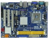
17 16 15 14 13 12 PANEL 1 PLED PWRBTN 1 HDLED RESET FSB1600 DDR2 800 Dual Channel DDRII_1 (64 bit, 240-piFnSmBod8ul0e)0 DDRII_2 (64 bit, 240-piFnSmBod8ul0e)0 24.4cm (9.6 in) SATAII_3 SATAII_4 6 7 8 9 10 11 1 PS2_USB_PWR1 Jumper 16 USB 2.0 Header (USB6_7, Blue) 2 775-Pin CPU Socket 17 USB - ASRock G31M-GS R2.0 | User Manual - Page 11
1.4 I/O Panel (G31M-GS) 1 2 3 4 5 6 10 9 8 7 1 PS/2 Mouse Port (Green) 2 panel audio cable to the front panel audio header. Please refer to below steps for the software setting of Multi-Streaming. For Windows® XP: After restarting your computer, you will find "Mixer" tool on your system - ASRock G31M-GS R2.0 | User Manual - Page 12
1.5 I/O Panel (G31M-S) 1 2 3 4 5 6 10 9 8 7 1 PS/2 Mouse Port (Green) 2 panel audio cable to the front panel audio header. Please refer to below steps for the software setting of Multi-Streaming. For Windows® XP: After restarting your computer, you will find "Mixer" tool on your system - ASRock G31M-GS R2.0 | User Manual - Page 13
G31M-GS / G31M-S is a Micro ATX form factor (9.6" x 7.2", 24.4 x 18.3 cm) motherboard. Before you install the motherboard, study the configuration of your chassis to ensure that the motherboard fits into it. Make sure to unplug the power cord before installing or removing the motherboard - ASRock G31M-GS R2.0 | User Manual - Page 14
the installation of Intel 775-LAND CPU, please follow the steps below. 775-Pin Socket Overview Before you insert the 775-LAND CPU into the socket, please check if the CPU surface is unclean or if there is any bent pin on the socket. Do not force to insert the CPU into the socket if above situation - ASRock G31M-GS R2.0 | User Manual - Page 15
to use the cap tab to handle and avoid kicking off the PnP cap. 2. This cap must be placed if returning the motherboard for after service. Step 4. Close the socket: Step 4-1. Rotate the load plate onto the IHS. Step 4-2. While pressing down lightly on load plate, engage the load lever. Step - ASRock G31M-GS R2.0 | User Manual - Page 16
Heatsink This motherboard is equipped with 775-Pin socket that supports Intel 775-LAND CPU. Please adopt the type of heatsink and cooling fan compliant with Intel 775-LAND CPU to dissipate heat. Before you installed the heatsink, you need to spray thermal interface material between the CPU and the - ASRock G31M-GS R2.0 | User Manual - Page 17
of Memory Modules (DIMM) G31M-GS / G31M-S motherboard provides two 240-pin DDR2 (Double Data Rate 2) DIMM slots, and supports Dual Channel Memory Technology. For dual channel configuration, you always need to install two identical (the same brand, speed, size and chip-type) memory modules - ASRock G31M-GS R2.0 | User Manual - Page 18
There are 2 PCI slots and 2 PCI Express slots on this motherboard. PCI slots: PCI slots are used to install expansion cards that have VGA card to PCIE2 (PCIE x16 slot) and adjust the "Internal Graphics Mode Select" BIOS option to [Enabled, 8MB] or [Enabled, 1MB], the onboard VGA will be enabled, - ASRock G31M-GS R2.0 | User Manual - Page 19
motherboard to meet EuP standard. With an ASRock EuP ready motherboard and a power supply that the 5VSB power efficiency is higher than 50% under 100mA current consumption, your system function under S3 (Suspend to RAM), S4 (Suspend to Disk), and S5 (Soft Off) will be disabled. EUP_LAN1 - ASRock G31M-GS R2.0 | User Manual - Page 20
800 / FSB0 / FSB1, 3-pin jumper, see p.10 No. 28) 1_2 1_2 Default 1_2 Note: If you want to overclock the FSB800-CPU (e.g. Cel400, E1000, E2000, E4000, E5000, E6000 series CPU) to FSB1066 on this motherboard, you need to adjust the jumpers. Please short pin2, pin3 for OC800 jumper. Otherwise, the - ASRock G31M-GS R2.0 | User Manual - Page 21
headers and connectors. Placing jumper caps over the headers and connectors will cause permanent damage of the motherboard motherboard to the IDE devices 80-conductor ATA 66/100 cable Note: Please refer to the instruction These Serial ATAII (SATAII) connectors support SATAII or SATA hard disk for - ASRock G31M-GS R2.0 | User Manual - Page 22
Definition Audio supports Jack Sensing, but the panel wire on the chassis must support HDA to function correctly. Please follow the instruction in our manual and chassis manual to install your system. 2. If you use AC'97 audio panel, please install it to the front panel audio header as below - ASRock G31M-GS R2.0 | User Manual - Page 23
"Mute" icon in "Front Mic" of "Playback" portion. For Windows® VistaTM / VistaTM 64-bit OS: Go to the "Front Mic" Tab in the Realtek Control panel. Click "Set Default Device" to make the Front Mic as the default record device. System Panel Header (9-pin PANEL1) (see p.10 No. 12) Chassis Speaker - ASRock G31M-GS R2.0 | User Manual - Page 24
(see p.10 No. 6) 12 24 Please connect an ATX power supply to this connector. 1 13 Though this motherboard provides 24-pin ATX power connector, 12 24 it can still work if you adopt a traditional 20-pin ATX power supply. To use the 20-pin ATX power supply, please plug your power supply along - ASRock G31M-GS R2.0 | User Manual - Page 25
remove the jumpers from pin 3 and pin 4. HITACHI Please use the Feature Tool, a DOS-bootable tool, for changing various ATA features. Please visit HITACHI's website for details: http://www.hitachigst.com/hdd/support/download.htm The above examples are just for your reference. For different SATAII - ASRock G31M-GS R2.0 | User Manual - Page 26
to your system can be auto-detected and listed on the support CD driver page. Please follow the order from up to bottom side to install those required drivers. Therefore, the drivers you install can work properly. 2 . 1 2 Untied Overclocking Technology This motherboard supports Untied Overclocking - ASRock G31M-GS R2.0 | User Manual - Page 27
requirements Advanced To set up the advanced BIOS features PCIPnP To set up the PCI features Boot To set up the default system device to locate and load the Operating System Security To set up the security features Chipset To set up the chipset features Exit To exit the current screen or - ASRock G31M-GS R2.0 | User Manual - Page 28
Boot Security Exit System Overview System Time System Date [14:00:09] [Mon 06/15/2009] BIOS Version : G31M-GS P1.00 Processor Type : Intel(R) Core(TM) 2 Duo CPU E6540 @ 2.33GHz (64bit) Processor Speed : 2333MHz Microcode Update : 6FB/B6 Cache Size : 4096KB Total Memory DDRII 1 DDRII - ASRock G31M-GS R2.0 | User Manual - Page 29
Boot Security Exit System Overview System Time System Date [14:00:09] [Mon 06/15/2009] BIOS Version : G31M-S P1.00 Processor Type : Intel(R) Core(TM) 2 Duo CPU E6540 @ 2.33GHz (64bit) Processor Speed : 2333MHz Microcode Update : 6FB/B6 Cache Size : 4096KB Total Memory DDRII 1 DDRII - ASRock G31M-GS R2.0 | User Manual - Page 30
. F6 key can be used for this operation. ASRock Instant Flash ASRock Instant Flash is a BIOS flash utility embedded in Flash ROM. This convenient BIOS update tool allows you to update system BIOS without entering operating systems first like MS-DOS or Windows®. Just launch this tool and save the new - ASRock G31M-GS R2.0 | User Manual - Page 31
1985-2005, American Megatrends, Inc. Setting wrong values in this section may cause the system to malfunction. 3.4.1 CPU Configuration BIOS SETUP UTILITY Advanced CPU Configuration Overclock Mode CPU Frequency (MHz) PCIE Frequency (MHz) Boot Failure Guard Spread Spectrum [Auto] [200] [100 - ASRock G31M-GS R2.0 | User Manual - Page 32
not support No-Excute Memory Protection. Hyper Threading Technology To enable this feature, it requires a computer system with an Intel Pentium® 4 processor that supports Hyper-Threading technology and an operating system that includes optimization for this technology, such as Microsoft® Windows® XP - ASRock G31M-GS R2.0 | User Manual - Page 33
you install Windows® VistaTM and want to enable this function, please set this item to [Enabled]. This item will be hidden if the current CPU does not support Intel (R) SpeedStep(tm) tech.. Please note that enabling this function may reduce CPU voltage and lead to system stability or compatibility - ASRock G31M-GS R2.0 | User Manual - Page 34
architecture that offers breakthrough perfor mance for the motherboard through efficient memory utilization. In Fixed mode, a fixed-size fragment of the system memory is allocated to the graphics core. In DVMT mode, the graphics driver allocates memory as needed for running graphics applications and - ASRock G31M-GS R2.0 | User Manual - Page 35
Panel Select [Auto], [Enabled] or [Disabled] for the onboard HD Audio Front Panel. OnBoard Lan This allows you to enable or disable the "OnBoard Lan" feature enable this function, please set this item to [Enabled]. Besides the BIOS option, you can also choose our Intelligent Energy Saver utility to - ASRock G31M-GS R2.0 | User Manual - Page 36
BIOS SETUP UTILITY Advanced ACPI Configuration Suspend To RAM RAM feature. Select [Auto] will enable this feature if the system supports system from the power-soft-off mode. PCI Devices Power On Use this item to enable or disable PCI devices to turn on the system power on the system. ACPI HPET Table - ASRock G31M-GS R2.0 | User Manual - Page 37
3.4.4 IDE Configuration BIOS SETUP UTILITY Advanced IDE Configuration ATA/IDE SATA 2, SATA 4], then SATAII_1, SATAII_3 will not work. Because Intel® ICH7 south bridge only supports four IDE devices under legacy OS (Windows NT), you have to choose [SATA 1, SATA 2, SATA 3, instruction. 37 - ASRock G31M-GS R2.0 | User Manual - Page 38
Supported :16Sectors :4 :MultiWord DMA-2 :Ultra DMA-5 :Supported [Auto] [Auto] [Auto] [Auto] [Auto] [Disabled] [Enabled] Select the type of device connected to the system hard disk information into BIOS, use a disk MB under DOS and Windows; for Netware and UNIX Auto]. If this feature is enabled, it - ASRock G31M-GS R2.0 | User Manual - Page 39
the S.M.A.R.T. (Self-Monitoring, Analysis, and Reporting Technology) feature. Configuration options: [Disabled], [Auto], [Enabled]. 32 to maximize the IDE hard disk data transfer rate. 3.4.5 PCIPnP Configuration BIOS SETUP UTILITY Advanced Advanced PCI / PnP Settings PCI Latency Timer PCI IDE - ASRock G31M-GS R2.0 | User Manual - Page 40
Floppy Configuration In this section, you may configure the type of your floppy drive. BIOS SETUP UTILITY Advanced Floppy Configuration Floppy A [1.44 MB 312"] Select the type of floppy drive connected to the system. +F1 F9 F10 ESC Select Screen Select Item Change Option General Help Load - ASRock G31M-GS R2.0 | User Manual - Page 41
to set the IRQ for the parallel port. Configuration options: [IRQ5] and [IRQ7]. 3.4.8 USB Configuration BIOS SETUP UTILITY Advanced USB Configuration USB Controller USB 2.0 Support Legacy USB Support [Enabled] [Enabled] [Enabled] To enable or disable the onboard USB controllers. +F1 F9 F10 ESC - ASRock G31M-GS R2.0 | User Manual - Page 42
allowed to use only under BIOS setup and Windows / Linux OS. 3.5 Hardware Health Event Monitoring Screen In this section, it allows you to monitor the status of the hardware on your system, including the parameters of the CPU temperature, motherboard temperature, CPU fan speed, chassis fan speed - ASRock G31M-GS R2.0 | User Manual - Page 43
for you to configure the boot settings and the boot priority. BIOS SETUP UTILITY Main Smart Advanced H/W Monitor Boot Security Exit Boot Settings Boot Settings Configuration Configure Settings during System Boot. 1st Boot Device 2nd Boot Device 3rd Boot Device 4th Boot Device Hard Disk Drives - ASRock G31M-GS R2.0 | User Manual - Page 44
Onboard LAN feature. Boot Up Num-Lock If this item is set to [On], it will automatically activate the Numeric Lock function after boot-up. 3.7 Security Screen In this section, you may set or change the supervisor/user password for the system. For the user password, you may also clear it. BIOS SETUP - ASRock G31M-GS R2.0 | User Manual - Page 45
Load 2nd User Defaults Save 3rd User Defaults Load 3rd User Defaults Exit system setup after saving the changes. F10 key can be used for this operation and exit setup?" Select [OK] to save the changes and exit the BIOS SETUP UTILITY. Discard Changes and Exit When you select this option, it will - ASRock G31M-GS R2.0 | User Manual - Page 46
to your OS documentation for more information. 4.2 Support CD Information The Support CD that came with the motherboard contains necessary drivers and useful utilities that enhance the motherboard features. 4.2.1 Running The Support CD To begin using the support CD, insert the CD into your CD-ROM
-
 1
1 -
 2
2 -
 3
3 -
 4
4 -
 5
5 -
 6
6 -
 7
7 -
8
-
9
-
10
-
11
-
12
-
13
-
14
-
15
-
16
-
17
-
18
-
19
-
20
-
21
-
22
-
23
-
24
-
25
-
26
-
27
-
28
-
29
-
30
-
31
-
32
-
33
-
34
-
35
-
36
-
37
-
38
-
39
-
40
-
41
-
42
-
43
-
44
-
45
-
46
 |
 |

1
G31M-GS / G31M-S
User Manual
Version 2.0
Published June 2009
Copyright©2009 ASRock INC. All rights reserved.