ASRock G31M-S User Manual
ASRock G31M-S Manual
 |
View all ASRock G31M-S manuals
Add to My Manuals
Save this manual to your list of manuals |
ASRock G31M-S manual content summary:
- ASRock G31M-S | User Manual - Page 1
G31M-GS / G31M-S User Manual Version 1.1 Published September 2008 Copyright©2008 ASRock INC. All rights reserved. 1 - ASRock G31M-S | User Manual - Page 2
without written consent of ASRock Inc. Products and corporate names appearing in this manual may or may not be intent to infringe. Disclaimer: Specifications and information contained in this manual are furnished for informational use battery adopted on this motherboard contains Perchlorate, a toxic - ASRock G31M-S | User Manual - Page 3
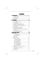
25 2.11 Driver Installation Guide 25 2.12 Untied Overclocking Technology 25 3 BIOS SETUP UTILITY 26 3.1 Introduction 26 3.1.1 BIOS Menu Bar 26 3.1.2 Navigation Keys 27 3.2 Main Screen 27 3.3 Smart Screen 29 3.4 Advanced Screen 30 3.4.1 CPU Configuration 30 3.4.2 Chipset Configuration 32 - ASRock G31M-S | User Manual - Page 4
4 Software Support 45 4.1 Install Operating System 45 4.2 Support CD Information 45 4.2.1 Running Support CD 45 4.2.2 Drivers Menu 45 4.2.3 Utilities Menu 45 4.2.4 Contact Information 45 4 - ASRock G31M-S | User Manual - Page 5
CPU support lists on ASRock website as well. ASRock website http://www.asrock.com If you require technical support related to this motherboard, please visit our website for specific information about the model you are using. www.asrock.com/support/index.asp 1.1 Package Contents ASRock G31M-GS / G31M - ASRock G31M-S | User Manual - Page 6
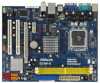
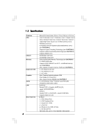
1.2 Specifications Platform CPU Chipset Memory Expansion Slot Graphics Audio LAN Rear Panel I/O 6 - Micro ATX Form Factor: 9.6-in x 7.5-in, 24.4 cm x 19.1 cm - LGA 775 for Intel® CoreTM 2 Extreme / CoreTM 2 Quad / CoreTM 2 Duo / Pentium® Dual Core / Celeron® Dual Core / Celeron®, supporting Penryn - ASRock G31M-S | User Manual - Page 7
Front panel audio connector - 2 x USB 2.0 headers (support 4 USB 2.0 ports) (see CAUTION 9) BIOS Feature - 4Mb AMI BIOS - AMI Legal BIOS - Supports "Plug and Play" - ACPI 1.1 Compliance Wake Up Events - Supports jumperfree - AMBIOS 2.3.1 Support - Supports Smart BIOS Support CD - Drivers - ASRock G31M-S | User Manual - Page 8
support frequency. CPU FSB Frequency Memory Support Frequency 1600 DDR2 800 1333 DDR2 667, DDR2 800 1066 DDR2 667, DDR2 800 800 DDR2 667, DDR2 800 6. Due to the operating system limitation, the actual memory size may be less than 4GB for the reservation for system usage under Windows® XP - ASRock G31M-S | User Manual - Page 9
website: http://www.asrock.com 12. Although this motherboard offers stepless control, it is not recommended to perform over-clocking. Frequencies other than the recommended CPU bus frequencies may cause the instability of the system or damage the CPU. 13. While CPU overheat is detected, the system - ASRock G31M-S | User Manual - Page 10
USB 2.0 T: USB0 B: USB1 Top: RJ-45 1 OC 800 1 FSB0 1 FSB1 Intel G31 Chipset LPT1 1 LAN PHY PCIE1 CMOS Battery CLRCMOS1 IDE1 Super IO CD1 RoHS AUDIO CODEC HD_AUDIO1 FLOPPY1 1 21 20 PCIE2 SATAII_3 PCI1 Intel ICH7 PCI2 CHA_FAN1 4Mb BIOS PANEL 1 PLED PWRBTN 1 HDLED RESET - ASRock G31M-S | User Manual - Page 11
(Pink) 7 USB 2.0 Ports (USB01) 8 VGA Port 9 COM Port 10 PS/2 Keyboard Port (Purple) * To enable Multi-Streaming function, you need to connect a front panel audio cable to the front panel audio header. Please refer to below steps for the software setting of Multi-Streaming. For Windows® XP: After - ASRock G31M-S | User Manual - Page 12
G31M-GS / G31M-S is a Micro ATX form factor (9.6" x 7.5", 24.4 x 19.1 cm) motherboard. Before you install the motherboard, study the configuration of your chassis to ensure that the motherboard fits into it. Make sure to unplug the power cord before installing or removing the motherboard - ASRock G31M-S | User Manual - Page 13
For the installation of Intel 775-LAND CPU, please follow the steps below. 775-Pin Socket Overview Before you insert the 775-LAND CPU into the socket, please check if the CPU surface is unclean or if there is any bent pin on the socket. Do not force to insert the CPU into the socket - ASRock G31M-S | User Manual - Page 14
CPU is within the socket and properly mated to the orient keys. Step 3. Remove PnP Cap (Pick and Place Cap): Use your left hand index finger and thumb to support PnP cap. 2. This cap must be placed if returning the motherboard for after service. Step 4. Close the socket: Step 4-1. Rotate the load - ASRock G31M-S | User Manual - Page 15
Heatsink This motherboard is equipped with 775-Pin socket that supports Intel 775-LAND CPU. Please adopt the type of heatsink and cooling fan compliant with Intel 775-LAND CPU to dissipate heat. Before you installed the heatsink, you need to spray thermal interface material between the CPU and the - ASRock G31M-S | User Manual - Page 16
2.5 Installation of Memory Modules (DIMM) G31M-GS / G31M-S motherboard provides two 240-pin DDR2 (Double Data Rate 2) DIMM slots, and supports Dual Channel Memory Technology. For dual channel configuration, you always need to install two identical (the same brand, speed, size and chip-type) memory - ASRock G31M-S | User Manual - Page 17
for PCI Express cards with x16 lane width graphics cards. If you install the add-on PCI Express VGA card to PCIE2 (PCIE x16 slot), the onboard VGA will be disabled. If you install the add-on PCI Express VGA card to PCIE2 (PCIE x16 slot) and adjust the "Internal Graphics Mode Select" BIOS option to - ASRock G31M-S | User Manual - Page 18
5V +5VSB or USB wake up events. Note: To select +5VSB, it requires 2 Amp and higher standby current provided by power supply. Clear CMOS (CLRCMOS1, 2-pin CMOS. The data in CMOS includes system setup information such as system password, date, time, and system setup parameters. To clear and reset - ASRock G31M-S | User Manual - Page 19
800 / FSB0 / FSB1, 3-pin jumper, see p.10 No. 27) 1_2 1_2 Default 1_2 Note: If you want to overclock the FSB800-CPU (e.g. Cel400, E1000, E2000, E4000, E5000, E6000 series CPU) to FSB1066 on this motherboard, you need to adjust the jumpers. Please short pin2, pin3 for OC800 jumper. Otherwise, the - ASRock G31M-S | User Manual - Page 20
, see p.10 No. 7) PIN1 IDE1 connect the blue end connect the black end to the motherboard to the IDE devices 80-conductor ATA 66/100 cable Note: Please refer to the instruction of your IDE device vendor for the details. SATAII_1 SATAII_3 SATAII_2 SATAII_4 Serial ATAII Connectors (SATAII_1 - ASRock G31M-S | User Manual - Page 21
2.0 ports on the I/O panel, there are two USB 2.0 headers on this motherboard. Each USB 2.0 header can support two USB 2.0 ports. This is an interface for print port cable that allows convenient connection of printer devices. Internal Audio Connector (4-pin CD1) (CD1: see p.10 No. 23) CD-L GND GND - ASRock G31M-S | User Manual - Page 22
BIOS Setup Utility. Enter Advanced Settings, and then select Chipset Configuration. Set the Front Panel Control option from [Auto] to [Enabled]. F. Enter Windows system. Click the icon on the lower right hand taskbar to enter Realtek HD Audio Manager. For Windows® 2000 / XP / XP DUMMY RESET# GND - ASRock G31M-S | User Manual - Page 23
Though this motherboard provides 4-Pin CPU fan (Quiet Fan) support, the 3-Pin CPU fan still can work successfully even without the fan speed control function. If you plan to connect the 3-Pin CPU fan to the CPU fan connector on this motherboard, please connect it to Pin 1-3. Pin 1-3 Connected 3-Pin - ASRock G31M-S | User Manual - Page 24
guide. Some default setting of SATAII hard disks may not be at SATAII mode, which operate with the best performance. In order to enable SATAII function, please follow the below instruction website for details: http://www.hitachigst.com/hdd/support/download.htm The above examples are just for your - ASRock G31M-S | User Manual - Page 25
to the motherboard's SATAII connector. STEP 4: Connect the other end of the SATA data cable to the SATA / SATAII hard disk. 2.11 Driver Installation Guide To install the drivers to your system, please insert the support CD to your optical drive first. Then, the drivers compatible to your system - ASRock G31M-S | User Manual - Page 26
reset button on the system chassis. You may also restart by turning the system off and then back on. Because the BIOS software is constantly being updated, the following BIOS security features Chipset To set up the chipset features Exit To exit the current screen or the BIOS SETUP UTILITY Use - ASRock G31M-S | User Manual - Page 27
System Overview System Time System Date [14:00:09] [Thu 07/31/2008] BIOS Version : G31M-GS P1.00 Processor Type : Intel(R) Core(TM) 2 Duo CPU E6540 @ 2.33GHz (64bit) Processor Speed : 2333MHz Microcode Update : 6FB/B6 Cache Size : 4096KB Total Memory DDRII 1 DDRII 2 : 1024MB with 8MB - ASRock G31M-S | User Manual - Page 28
System Overview System Time System Date [14:00:09] [Thu 07/31/2008] BIOS Version : G31M-S P1.00 Processor Type : Intel(R) Core(TM) 2 Duo CPU E6540 @ 2.33GHz (64bit) Processor Speed : 2333MHz Microcode Update : 6FB/B6 Cache Size : 4096KB Total Memory DDRII 1 DDRII 2 : 1024MB with 8MB - ASRock G31M-S | User Manual - Page 29
SETUP UTILITY. Load BIOS Defaults Load BIOS default values for all the setup questions. F9 key can be used for this operation. Load Performance Setup Default (IDE/SATA) This performance setup default may not be compatible with all system configurations. If system boot failure occurs after loading - ASRock G31M-S | User Manual - Page 30
, you may set the configurations for the following items: CPU Configuration, Chipset Configuration, ACPI Configuration, IDE Configuration, PCIPnP Configuration, Floppy Configuration, SuperIO Configuration, and USB Configuration. BIOS SETUP UTILITY Main Smart Advanced H/W Monitor Boot Security Exit - ASRock G31M-S | User Manual - Page 31
value, please disable the option " Intel (R) SpeedStep(tm) tech." in advance. Enhance Halt State All processors support the Halt State (C1). The C1 state is supported through the native processor instructions HLT and MWAIT and requires no hardware support from the chipset. In the C1 power state, the - ASRock G31M-S | User Manual - Page 32
] if using Microsoft® Windows® XP, or Linux kernel version 2.4.18 or higher. This option will be hidden if the installed CPU does not support Hyper-Threading technology. Intel (R) SpeedStep(tm) tech. Intel (R) SpeedStep(tm) tech. is Intel's new power saving technology. Processor can switch between - ASRock G31M-S | User Manual - Page 33
will allow better tolerance for memory compatibility when it is set to [ motherboard through efficient memory utilization. In Fixed mode, a fixed-size fragment of the system memory is allocated to the graphics core. In DVMT mode, the graphics driver allocates memory as needed for running graphics - ASRock G31M-S | User Manual - Page 34
Audio Select [Auto], [Enabled] or [Disabled] for the onboard HD Audio feature. If you select [Auto], the onboard HD Audio will be disabled when PCI Sound Card enable this function, please set this item to [Enabled]. Besides the BIOS option, you can also choose our Intelligent Energy Saver utility to - ASRock G31M-S | User Manual - Page 35
3.4.3 ACPI Configuration BIOS SETUP UTILITY Advanced ACPI the Suspend-to-RAM feature. Select [Auto] will enable this feature if the system supports it. Restore on AC/Power Loss This allows you to set the power state after you plan to use this motherboard to submit Windows® VistaTM certification. 35 - ASRock G31M-S | User Manual - Page 36
Compatible] when you install legacy OS (Windows NT). If native OS (Windows 2000 / XP) is installed, please select [Enhanced]. When [Compatible , SATAII_3 will not work. Because Intel® ICH7 south bridge only supports four IDE devices under legacy OS (Windows NT), you have to choose [ instruction. 36 - ASRock G31M-S | User Manual - Page 37
), such as MO. LBA/Large Mode Use this item to select the LBA/Large mode for a hard disk > 512 MB under DOS and Windows; for Netware and UNIX user, select [Disabled] to disable the LBA/Large mode. Block (Multi-Sector Transfer) The default value of this item is [Auto]. If this feature - ASRock G31M-S | User Manual - Page 38
to maximize the IDE hard disk data transfer rate. 3.4.5 PCIPnP Configuration BIOS SETUP UTILITY Advanced Advanced PCI / PnP Settings PCI Latency Timer PCI IDE keep the default value unless the installed PCI expansion cards' specifications require other settings. PCI IDE BusMaster Use this item to - ASRock G31M-S | User Manual - Page 39
Load Defaults Save and Exit Exit v02.54 (C) Copyright 1985-2005, American Megatrends, Inc. 3.4.7 Super IO Configuration BIOS SETUP UTILITY Advanced Configure Super IO Chipset OnBoard Floppy Controller Serial Port Address Parallel Port Address Parallel Port Mode EPP Version ECP Mode DMA Channel - ASRock G31M-S | User Manual - Page 40
parallel port. Configuration options: [IRQ5] and [IRQ7]. 3.4.8 USB Configuration BIOS SETUP UTILITY Advanced USB Configuration USB Controller USB 2.0 Support Legacy USB Support [Enabled] [Enabled] [BIOS Setup Only] To enable or disable the onboard USB controllers. +F1 F9 F10 ESC Select Screen - ASRock G31M-S | User Manual - Page 41
Only] - USB devices are allowed to use only under BIOS setup and Windows / Linux OS. 3.5 Hardware Health Event Monitoring Screen In this section, it allows you to monitor the status of the hardware on your system, including the parameters of the CPU temperature, motherboard temperature, CPU fan - ASRock G31M-S | User Manual - Page 42
you to configure the boot settings and the boot priority. BIOS SETUP UTILITY Main Smart Advanced H/W Monitor Boot Security Exit Boot Device] [HDD: PM - HDS722580VL] [CD / DVD: 3S - CD - ROM C] [USB] Select Screen Select Item Enter Go to Sub Screen F1 General Help F9 Load Defaults F10 Save and - ASRock G31M-S | User Manual - Page 43
function after boot-up. 3.7 Security Screen In this section, you may set or change the supervisor/user password for the system. For the user password, you may also clear it. BIOS SETUP UTILITY Main Smart Advanced H/W Monitor Boot Security Exit Security Settings Supervisor Password : Not Installed - ASRock G31M-S | User Manual - Page 44
3.8 Exit Screen BIOS SETUP UTILITY Main Smart Advanced H/W Monitor Boot Security Exit Exit Options Save Changes and Exit Discard Changes and Exit Discard Changes Would you like to save current setting user defaults ? Save 1st User Defaults Load 1st User Defaults Save 2nd User Defaults Load 2nd - ASRock G31M-S | User Manual - Page 45
install the necessary drivers to activate the devices. 4.2.3 Utilities Menu The Utilities Menu shows the applications software that the motherboard supports. Click on a specific item then follow the installation wizard to install it. 4.2.4 Contact Information If you need to contact ASRock or want to
-
 1
1 -
 2
2 -
 3
3 -
 4
4 -
 5
5 -
 6
6 -
 7
7 -
8
-
9
-
10
-
11
-
12
-
13
-
14
-
15
-
16
-
17
-
18
-
19
-
20
-
21
-
22
-
23
-
24
-
25
-
26
-
27
-
28
-
29
-
30
-
31
-
32
-
33
-
34
-
35
-
36
-
37
-
38
-
39
-
40
-
41
-
42
-
43
-
44
-
45
 |
 |

1
G31M-GS / G31M-S
User Manual
Version 1.1
Published September 2008
Copyright©2008 ASRock INC. All rights reserved.