ASRock G31M-VS2 User Manual
ASRock G31M-VS2 Manual
 |
View all ASRock G31M-VS2 manuals
Add to My Manuals
Save this manual to your list of manuals |
ASRock G31M-VS2 manual content summary:
- ASRock G31M-VS2 | User Manual - Page 1
G31M-VS2 User Manual Version 1.2 Published March 2010 Copyright©2010 ASRock INC. All rights reserved. 1 - ASRock G31M-VS2 | User Manual - Page 2
without written consent of ASRock Inc. Products and corporate names appearing in this manual may or may not be intent to infringe. Disclaimer: Specifications and information contained in this manual are furnished for informational use battery adopted on this motherboard contains Perchlorate, a toxic - ASRock G31M-VS2 | User Manual - Page 3
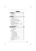
24 2.11 Driver Installation Guide 24 2.12 Untied Overclocking Technology 24 3 BIOS SETUP UTILITY 25 3.1 Introduction 25 3.1.1 BIOS Menu Bar 25 3.1.2 Navigation Keys 26 3.2 Main Screen 26 3.3 Smart Screen 27 3.4 Advanced Screen 28 3.4.1 CPU Configuration 28 3.4.2 Chipset Configuration 30 - ASRock G31M-VS2 | User Manual - Page 4
4 Software Support 43 4.1 Install Operating System 43 4.2 Support CD Information 43 4.2.1 Running Support CD 43 4.2.2 Drivers Menu 43 4.2.3 Utilities Menu 43 4.2.4 Contact Information 43 4 - ASRock G31M-VS2 | User Manual - Page 5
and CPU support lists on ASRock website as well. ASRock website http://www.asrock.com If you require technical support related to this motherboard, please visit our website for specific information about the model you are using. www.asrock.com/support/index.asp 1.1 Package Contents ASRock G31M-VS2 - ASRock G31M-VS2 | User Manual - Page 6
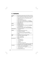
Hyper-Threading Technology (see CAUTION 1) - Supports Untied Overclocking Technology (see CAUTION 2) - Supports EM64T CPU - Northbridge: Intel® G31 - Southbridge: Intel® ICH7 - Dual Channel DDR2 Memory Technology (see CAUTION 3) - 2 x DDR2 DIMM slots - Supports DDR2 800/667 non-ECC, un-buffered - ASRock G31M-VS2 | User Manual - Page 7
- ACPI 1.1 Compliance Wake Up Events - Supports jumperfree - AMBIOS 2.3.1 Support - VCCM Voltage Multi-adjustment - Supports Smart BIOS Support CD - Drivers, Utilities, AntiVirus Software (Trial Version), ASRock Software Suite (CyberLink DVD Suite and Creative Sound Blaster X-Fi MB) (OEM and - ASRock G31M-VS2 | User Manual - Page 8
connect SATA hard disk to SATAII connector directly. 7. Power Management for USB 2.0 works fine under Microsoft® Windows® 7 64-bit / 7 / VistaTM 64-bit / VistaTM / XP 64-bit / XP SP1 or SP2. 8. It is a user-friendly ASRock overclocking tool which allows you to surveil your system by hardware monitor - ASRock G31M-VS2 | User Manual - Page 9
10. ASRock Instant Flash is a BIOS flash utility embedded in Flash ROM. This convenient BIOS update tool allows you to update system BIOS without entering operating systems first like MS-DOS or Windows®. With this utility, you can press key during the POST or press key to BIOS setup menu - ASRock G31M-VS2 | User Manual - Page 10
FSB1333 DDR2 800 Dual Channel VGA1 G31M-VS2 USB 2.0 T: USB2 B: USB3 1 Top: Line In Center: Line Out Bottom: Mic In 24 USB 2.0 T: USB0 B: USB1 Top: RJ-45 Super IO Intel G31 Chipset LAN 23 HD_AUDIO1 PHY LPT1 1 22 6 CD1 21 PCIE1 AUDIO CODEC CMOS 20 4Mb BIOS Battery RoHS Intel - ASRock G31M-VS2 | User Manual - Page 11
) 5 Line Out (Lime) 6 Microphone (Pink) 7 USB 2.0 Ports (USB01) 8 VGA Port 9 COM Port 10 PS/2 Keyboard Port (Purple) * There are two LED Audio Deck" tool on your system. Please follow below instructions according to the OS you install. For Windows® XP / XP 64-bit OS: Please click "VIA HD Audio - ASRock G31M-VS2 | User Manual - Page 12
G31M-VS2 is a Micro ATX form factor (8.9" x 6.7", 22.6 x 17.0 cm) motherboard. Before you install the motherboard, study the configuration of your chassis to ensure that the motherboard fits into it. Make sure to unplug the power cord before installing or removing the motherboard. Failure - ASRock G31M-VS2 | User Manual - Page 13
For the installation of Intel 775-LAND CPU, please follow the steps below. 775-Pin Socket Overview Before you insert the 775-LAND CPU into the socket, please check if the CPU surface is unclean or if there is any bent pin on the socket. Do not force to insert the CPU into the socket - ASRock G31M-VS2 | User Manual - Page 14
CPU is within the socket and properly mated to the orient keys. Step 3. Remove PnP Cap (Pick and Place Cap): Use your left hand index finger and thumb to support PnP cap. 2. This cap must be placed if returning the motherboard for after service. Step 4. Close the socket: Step 4-1. Rotate the load - ASRock G31M-VS2 | User Manual - Page 15
are securely fastened and in good contact with each other. Then connect the CPU fan to the CPU_FAN connector (CPU_FAN1, see page 10, No. 3). For proper installation, please kindly refer to the instruction manuals of your CPU fan and heatsink. Below is an example to illustrate the installation of the - ASRock G31M-VS2 | User Manual - Page 16
2.5 Installation of Memory Modules (DIMM) G31M-VS2 motherboard provides two 240-pin DDR2 (Double Data Rate 2) DIMM slots, and supports Dual Channel Memory Technology. For dual channel configuration, you always need to install two identical (the same brand, speed, size and chip-type) memory modules - ASRock G31M-VS2 | User Manual - Page 17
) There are 1 PCI slot and 1 PCI Express slot on this motherboard. PCI slot: PCI slot is used to install expansion card that has Express VGA card to PCIE1 (PCIE x16 slot) and adjust the "Internal Graphics Mode Select" BIOS option to [Enabled, 1MB] or [Enabled, 8MB], the onboard VGA will be enabled, - ASRock G31M-VS2 | User Manual - Page 18
are "Short" when jumper cap is placed on these 2 pins. Jumper Setting Description PS2_USB_PWR1 1_2 (see p.10 No. 1) 2_3 Short pin2, pin3 to enable +5VSB (standby) for PS/2 +5V +5VSB or USB wake up events. Note: To select +5VSB, it requires 2 Amp and higher standby current provided by - ASRock G31M-VS2 | User Manual - Page 19
! Primary IDE connector (Blue) (39-pin IDE1, see p.10 No. 8) PIN1 IDE1 connect the blue end connect the black end to the motherboard to the IDE devices 80-conductor ATA 66/100 cable Note: Please refer to the instruction of your IDE device vendor for the details. Serial ATAII Connectors - ASRock G31M-VS2 | User Manual - Page 20
, there are two USB 2.0 headers on this motherboard. Each USB 2.0 header can support two USB 2.0 ports. Print Port Header (25-pin LPT1) (see p.10 No. 24) AFD# ERROR# PINIT# SLIN# GND 1 SPD7 SPD6 ACK# SPD5 BUSY SPD4 PE SPD3 SLCT SPD2 SPD1 SPD0 STB# Internal Audio Connector (4-pin CD1 - ASRock G31M-VS2 | User Manual - Page 21
Fan Connector (4-pin CPU_FAN1) (see p.10 No. 3) +12V CPU_FAN_SPEED GND FAN_SPEED_CONTROL 1 2 3 4 Please connect a CPU fan cable to this connector and match the black wire to the ground pin. Though this motherboard provides 4-Pin CPU fan (Quiet Fan) support, the 3-Pin CPU fan still can work - ASRock G31M-VS2 | User Manual - Page 22
ATX 12V Connector (4-pin ATX12V2) (see p.10 No. 2) Please note that it is necessary to connect a power supply with ATX 12V plug to this connector so that it can provides sufficient power. Failing to do so will cause the failure to power up. 22 - ASRock G31M-VS2 | User Manual - Page 23
guide. Some default setting of SATAII hard disks may not be at SATAII mode, which operate with the best performance. In order to enable SATAII function, please follow the below instruction website for details: http://www.hitachigst.com/hdd/support/download.htm The above examples are just for your - ASRock G31M-VS2 | User Manual - Page 24
auto-detected and listed on the support CD driver page. Please follow the order from up to bottom side to install those required drivers. Therefore, the drivers you install can work properly. 2 . 1 2 Untied Overclocking Technology This motherboard supports Untied Overclocking Technology, which means - ASRock G31M-VS2 | User Manual - Page 25
the BIOS SETUP UTILITY to configure your system. The SPI Memory on the motherboard stores the BIOS SETUP UTILITY. You may run the BIOS SETUP off and then back on. Because the BIOS software is constantly being updated, the following BIOS setup screens and descriptions are for reference purpose - ASRock G31M-VS2 | User Manual - Page 26
Exit System Overview System Time System Date [14:00:09] [Fri 01/08/2010] BIOS Version : G31M-VS2 P1.00 Processor Type : Intel (R) CPU 2.80GHz (64bit) Processor Speed : 2800MHz Microcode Update : F62/F Cache Size : 4096KB Total Memory DDRII 1 DDRII 2 : 1024MB with 8MB shared memory and - ASRock G31M-VS2 | User Manual - Page 27
operation. ASRock Instant Flash ASRock Instant Flash is a BIOS flash utility embedded in Flash ROM. This convenient BIOS update tool allows you to update system BIOS without entering operating systems first like MS-DOS or Windows®. Just launch this tool and save the new BIOS file to your USB flash - ASRock G31M-VS2 | User Manual - Page 28
section, you may set the configurations for the following items: CPU Configuration, Chipset Configuration, ACPI Configuration, Storage Configuration, PCIPnP Configuration, SuperIO Configuration, and USB Configuration. BIOS SETUP UTILITY Main Smart Advanced H/W Monitor Boot Security Exit Advanced - ASRock G31M-VS2 | User Manual - Page 29
to allow you changing the ratio value of this motherboard. If the CPU you adopt supports EIST (Intel (R) SpeedStep(tm) tech.), and you plan to adjust the ratio value, please disable the option " Intel (R) SpeedStep(tm) tech." in advance. Intel (R) Virtualization tech. When this option is set to - ASRock G31M-VS2 | User Manual - Page 30
Windows® XP and select [Auto], you need to set the "Power Schemes" as "Portable/Laptop" to enable this function. If you install Windows® VistaTM and want to enable this function, please set this item to [Enabled]. This item will be hidden if the current CPU does not support Intel (R) SpeedStep - ASRock G31M-VS2 | User Manual - Page 31
offers breakthrough perfor mance for the motherboard through efficient memory utilization. In under Windows® VistaTM OS because the driver will Audio Select [Auto], [Enabled] or [Disabled] for the onboard HD Audio feature. If you select [Auto], the onboard HD Audio will be disabled when PCI Sound - ASRock G31M-VS2 | User Manual - Page 32
[Auto], [Enabled] or [Disabled] for the onboard HD Audio Front Panel. OnBoard Lan This allows you to enable or If you want to enable this function, please set this item to [Enabled]. Besides the BIOS option, you can also choose our Intelligent Energy Saver utility to enable this function. DRAM - ASRock G31M-VS2 | User Manual - Page 33
3.4.3 ACPI Configuration BIOS SETUP UTILITY Advanced ACPI the Suspend-to-RAM feature. Select [Auto] will enable this feature if the system supports it. Restore on AC/Power Loss This allows you to set the power state after you plan to use this motherboard to submit Windows® VistaTM certification. 33 - ASRock G31M-VS2 | User Manual - Page 34
BIOS NT) device is used. Set [Enhanced] when Native OS (Win2000 / XP) is used. +F1 F9 F10 ESC Select Screen Select Item Change not work, only IDE will work. Because Intel® ICH7 south bridge only supports four IDE devices under legacy OS (Windows NT), you have to choose [SATA 1, instruction. 34 - ASRock G31M-VS2 | User Manual - Page 35
BIOS SETUP UTILITY Advanced Primary IDE Master Device Vendor Size LBA Mode Block Mode PIO Mode Async DMA Ultra DMA S.M.A.R.T. Type LBA/Large Mode Block (Multi-Sector Transfer) PIO Mode DMA Mode S.M.A.R.T. 32Bit Data Transfer :Hard Disk :ST340014A :40.0 GB :Supported DOS and Windows; for Netware - ASRock G31M-VS2 | User Manual - Page 36
to maximize the IDE hard disk data transfer rate. 3.4.5 PCIPnP Configuration BIOS SETUP UTILITY Advanced Advanced PCI / PnP Settings PCI Latency Timer PCI IDE default value unless the installed PCI expansion cards' specifications require other settings. PCI IDE BusMaster Use this item to enable - ASRock G31M-VS2 | User Manual - Page 37
SETUP UTILITY Advanced Configure Super IO Chipset Serial Port Address Parallel Port Address Parallel Port Mode EPP Version ECP Mode DMA Channel Parallel Port IRQ [3F8 / IRQ4] [378] [ECP + EPP] [1.9] [DMA3] [IRQ7] Allow BIOS to Enable or Disable Floppy Controller. +F1 F9 F10 ESC Select Screen - ASRock G31M-VS2 | User Manual - Page 38
or disable the use of USB controller. USB 2.0 Support Use this item to enable or disable the USB 2.0 support. Legacy USB Support Use this option to select legacy support for USB devices. There are four configuration options: [Enabled], [Auto], [Disabled] and [BIOS Setup Only]. The default value - ASRock G31M-VS2 | User Manual - Page 39
you to monitor the status of the hardware on your system, including the parameters of the CPU temperature, motherboard temperature, CPU fan speed, chassis fan speed, and the critical voltage. BIOS SETUP UTILITY Main Smart Advanced H/W Monitor Boot Security Exit Hardware Health Event Monitoring - ASRock G31M-VS2 | User Manual - Page 40
you to configure the boot settings and the boot priority. BIOS SETUP UTILITY Main Smart Advanced H/W Monitor Boot Security Exit Boot Device] [HDD: PM - HDS722580VL] [CD / DVD: 3S - CD - ROM C] [USB] Select Screen Select Item Enter Go to Sub Screen F1 General Help F9 Load Defaults F10 Save and - ASRock G31M-VS2 | User Manual - Page 41
section, you may set or change the supervisor/user password for the system. For the user password, you may also clear it. BIOS SETUP UTILITY Main Smart Advanced H/W Monitor Boot Security Exit Security Settings Supervisor Password : Not Installed User Password : Not Installed Change Supervisor - ASRock G31M-VS2 | User Manual - Page 42
and exit setup?" Select [OK] to save the changes and exit the BIOS SETUP UTILITY. Discard Changes and Exit When you select this option, it message, "Discard changes and exit setup?" Select [OK] to exit the BIOS SETUP UTILITY without saving any changes. Discard Changes When you select this option - ASRock G31M-VS2 | User Manual - Page 43
install the necessary drivers to activate the devices. 4.2.3 Utilities Menu The Utilities Menu shows the applications software that the motherboard supports. Click on a specific item then follow the installation wizard to install it. 4.2.4 Contact Information If you need to contact ASRock or want to
-
 1
1 -
 2
2 -
 3
3 -
 4
4 -
 5
5 -
 6
6 -
 7
7 -
8
-
9
-
10
-
11
-
12
-
13
-
14
-
15
-
16
-
17
-
18
-
19
-
20
-
21
-
22
-
23
-
24
-
25
-
26
-
27
-
28
-
29
-
30
-
31
-
32
-
33
-
34
-
35
-
36
-
37
-
38
-
39
-
40
-
41
-
42
-
43
 |
 |

1
G31M-VS2
User Manual
Version 1.
2
Published March 2010
Copyright©2010 ASRock INC. All rights reserved.