ASRock G41C-GS R2.0 User Manual
ASRock G41C-GS R2.0 Manual
 |
View all ASRock G41C-GS R2.0 manuals
Add to My Manuals
Save this manual to your list of manuals |
ASRock G41C-GS R2.0 manual content summary:
- ASRock G41C-GS R2.0 | User Manual - Page 1
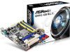
G41C-GS R2.0 User Manual Version 1.0 Published February 2014 Copyright©2014 ASRock INC. All rights reserved. 1 - ASRock G41C-GS R2.0 | User Manual - Page 2
purchaser for backup purpose, without written consent of ASRock Inc. Products and corporate names appearing in this manual may or may not be registered trademarks or copyrights USA ONLY The Lithium battery adopted on this motherboard contains Perchlorate, a toxic substance controlled in Perchlorate - ASRock G41C-GS R2.0 | User Manual - Page 3
2.4 Installation of Heatsink and CPU fan 16 2.5 Installation of Memory Modules (DIMM 17 2.6 Expansion Slots (PCI and PCI Express Slots 19 2.7 Jumpers Setup 20 2.8 Onboard Headers and Connectors 21 2.9 Driver Installation Guide 25 2.10 Untied Overclocking Technology 25 3 BIOS SETUP UTILITY 26 - ASRock G41C-GS R2.0 | User Manual - Page 4
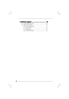
4 Software Support 51 4.1 Install Operating System 51 4.2 Support CD Information 51 4.2.1 Running Support CD 51 4.2.2 Drivers Menu 51 4.2.3 Utilities Menu 51 4.2.4 Contact Information 51 4 - ASRock G41C-GS R2.0 | User Manual - Page 5
for specific information about the model you are using. www.asrock.com/support/index.asp 1.1 Package Contents ASRock G41C-GS R2.0 Motherboard (Micro ATX Form Factor) ASRock G41C-GS R2.0 Quick Installation Guide ASRock G41C-GS R2.0 Support CD Two Serial ATA (SATA) Data Cables (Optional) One I/O Panel - ASRock G41C-GS R2.0 | User Manual - Page 6
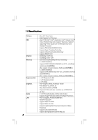
FSB1333/1066/800/533 MHz - Supports Hyper-Threading Technology - Supports Untied Overclocking Technology - Supports EM64T CPU - Northbridge: Intel® G41 - Southbridge: Intel® ICH7 - Dual Channel DDR3/DDR2 Memory Technology - 2 x DDR3 DIMM Slots - Supports DDR3 1333(OC)/1066/800 non-ECC, un-buffered - ASRock G41C-GS R2.0 | User Manual - Page 7
Support 4 USB 2.0 ports) (Supports ESD Protection (ASRock Full Spike Protection)) BIOS Feature - 8Mb AMI Legal BIOS - Supports Plug and Play - ACPI 1.1 compliant wake up events - Supports jumperfree - VCCM, NB, VTT, GTLRef Voltage multi-adjustment - Supports Smart BIOS Support CD - Drivers - ASRock G41C-GS R2.0 | User Manual - Page 8
Support Frequency 1333 DDR3 800, DDR3 1066, DDR3 1333 DDR2 667, DDR2 800 1066 DDR3 800, DDR3 1066 DDR2 667, DDR2 800 800 DDR3 800 DDR2 667, DDR2 800 533 DDR3 800 DDR2 533 * DDR3 1333 memory modules will operate in overclocking mode. * When you use a FSB533-CPU on this motherboard - ASRock G41C-GS R2.0 | User Manual - Page 9
Boot allows you to enter your WindowsR desktop in a few seconds. ASRock Instant Flash ASRock Instant Flash is a BIOS flash utility embedded in Flash ROM. This convenient BIOS update tool allows you to update system BIOS without entering operating systems first like MS-DOS or WindowsR. With this - ASRock G41C-GS R2.0 | User Manual - Page 10
of Your Data: With the status window, you can easily recognize which data streams you are transferring currently. ASRock XFast RAM ASRock XFast RAM fully utilizes the memory space that cannot be used under WindowsR OS 32-bit CPU. ASRock XFast RAM shortens the loading time of previously visited - ASRock G41C-GS R2.0 | User Manual - Page 11
1 PCI1 RoHS PCI2 8Mb BIOS PANEL 1 PLED PWRBTN 1 HDLED RESET Intel ICH7 IDE1 USB4_5 1 1 USB6_7 SATAII_1 SATAII_2 SPEAKER1 1 PWR_FAN1 CHA_FAN1 SATAII_3 SATAII_4 19 18 17 16 15 14 13 12 7 8 9 10 11 1 PS2_USB_PWR1 Jumper 2 ATX 12V Connector (ATX12V2) 3 CPU Fan Connector (CPU_FAN1 - ASRock G41C-GS R2.0 | User Manual - Page 12
Pink) 6 USB 2.0 Ports (USB01) 7 USB 2.0 Ports (USB23) 8 VGA Port 9 COM Port 10 PS/2 Keyboard Port (Purple) * There are two LED next to the LAN port. Please refer to to below steps for the software setting of Multi-Streaming. For Windows® XP: After restarting your computer, you will find "Mixer" - ASRock G41C-GS R2.0 | User Manual - Page 13
Chapter 2 Installation G41C-GS R2.0 is a Micro ATX form factor motherboard. Before you install the motherboard, study the configuration of your chassis to ensure that the motherboard fits into it. Make sure to unplug the power cord before installing or removing the motherboard. Failure to do so may - ASRock G41C-GS R2.0 | User Manual - Page 14
For the installation of Intel 775-LAND CPU, please follow the steps below. 775-Pin Socket Overview Before you insert the 775-LAND CPU into the socket, please check if the CPU surface is unclean or if there is any bent pin on the socket. Do not force to insert the CPU into the socket if - ASRock G41C-GS R2.0 | User Manual - Page 15
CPU is within the socket and properly mated to the orient keys. Step 3. Remove PnP Cap (Pick and Place Cap): Use your left hand index finger and thumb to support PnP cap. 2. This cap must be placed if returning the motherboard for after service. Step 4. Close the socket: Step 4-1. Rotate the load - ASRock G41C-GS R2.0 | User Manual - Page 16
Heatsink This motherboard is equipped with 775-Pin socket that supports Intel 775-LAND CPU. Please adopt the type of heatsink and cooling fan compliant with Intel 775-LAND CPU to dissipate heat. Before you installed the heatsink, you need to spray thermal interface material between the CPU and the - ASRock G41C-GS R2.0 | User Manual - Page 17
2.5 Installation of Memory Modules (DIMM) This motherboard provides two 240-pin DDR2 (Double Data Rate 2) DIMM slots and two 240-pin DDR3 (Double Data Rate 3) DIMM slots, and supports Dual Channel Memory Technology. For dual channel configuration, you always need to install identical (the same brand - ASRock G41C-GS R2.0 | User Manual - Page 18
matches the break on the slot. notch break notch break The DIMM only fits in one correct orientation. It will cause permanent damage to the motherboard and the DIMM if you force the DIMM into the slot at incorrect orientation. Step 3. Firmly insert the DIMM into the slot until the retaining - ASRock G41C-GS R2.0 | User Manual - Page 19
There are 2 PCI slots and 2 PCI Express slots on this motherboard. PCI slots: PCI slots are used to install expansion cards that VGA card to PCIE1 (PCIE x16 slot) and adjust the BIOS options "Primary Graphics Adapter" to [Onboard] and "Share Memory" to [Auto], then the onboard VGA will be enabled, - ASRock G41C-GS R2.0 | User Manual - Page 20
No. 23) EUP_LAN1 EUP_AUDIO1 Default (Enable EuP) Note: EUP_AUDIO jumper design decreases the power consumption of this motherboard to meet EuP standard. With an ASRock EuP ready motherboard and a power supply that the 5VSB power efficiency is higher than 50% under 100mA current consumption, your - ASRock G41C-GS R2.0 | User Manual - Page 21
p.11 No. 22) FSB1 Default If you adopt FSB1333-CPU and DDR3 1333 memory module on this motherboard, you need to adjust the jumper. Please short pin2, pin3 for FSB1 jumper. Otherwise, the CPU and memory module may not work properly on this motherboard. Please refer to below jumper setting. FSB1 - ASRock G41C-GS R2.0 | User Manual - Page 22
hard disk or the SATAII connector on the motherboard. USB 2.0 Headers (9-pin USB6_7) (see supports Jack Sensing, but the panel wire on the chassis must support HDA to function correctly. Please follow the instruction in our manual and chassis manual panel. E. Enter BIOS Setup Utility. Enter Advanced Settings - ASRock G41C-GS R2.0 | User Manual - Page 23
and match the black wire to the ground pin. Please connect a CPU fan cable to this connector and match the black wire to the ground pin. Though this motherboard provides 4-Pin CPU fan (Quiet Fan) support, the 3-Pin CPU fan still can work successfully even without the fan speed control function - ASRock G41C-GS R2.0 | User Manual - Page 24
plug to this connector so that it can provides sufficient power. Failing to do so will cause the failure to power up. This motherboard supports CASE OPEN detection feature that detects if the chassis cover has been removed. This feature requires a chassis with chassis intrusion detection design. 24 - ASRock G41C-GS R2.0 | User Manual - Page 25
order from up to bottom side to install those required drivers. Therefore, the drivers you install can work properly. 2.10 Untied Overclocking Technology This motherboard supports Untied Overclocking Technology, which means during overclocking, FSB enjoys better margin due to fixed PCI / PCIE buses - ASRock G41C-GS R2.0 | User Manual - Page 26
BIOS SETUP UTILITY to configure your system. The SPI Memory on the motherboard stores the BIOS SETUP UTILITY. You may run the BIOS Because the BIOS software is constantly being updated, the following BIOS setup screens set up overclocking features Advanced To set up the advanced BIOS features H/W - ASRock G41C-GS R2.0 | User Manual - Page 27
:09] [Tue 12/01/2009] Use [Enter], [TAB] or [SHIFT-TAB] to select a field. BIOS Version : G41C-GS P1.00 Processor Type : Intel (R) Core (TM) 2 Duo CPU E8200 @ 2.66GHz (64bit) Processor Speed : 2666MHz Microcode Update : 10676/60C Cache Size : 6144KB Total Memory DDRII1 DDRII2 DDR3_1 DDR3_2 - ASRock G41C-GS R2.0 | User Manual - Page 28
Exit OC Tweaker Settings DRAM Frequency DRAM Timing Configuration Ratio CMOS Setting 8 Intel (R) SpeedStep (tm) tech. Overclock Mode CPU Frequency (MHz) PCIE Frequency (MHz) [Auto] [8] [Auto] [Auto] [333] [100] If you adopt DDR3 1333 pls. adjust jumper set MB before apply it. For FSB1333 - ASRock G41C-GS R2.0 | User Manual - Page 29
BIOS SETUP UTILITY OC Tweaker DRAM Timing Control DRAM tCL 6 DRAM tRCD 6 DRAM tRP 6 DRAM tRAS 15 DRAM tRFC 44 DRAM tWR 6 DRAM tWTR 4 DRAM tRRD 3 DRAM tRTP 4 [Auto] [Auto] [Auto] [Auto] [Auto] [Auto] [Auto] [Auto] [Auto] DRAM tCL Value DDR2 Min = 3 Max = 7 DDR3 Min = 5 Max = 10 - ASRock G41C-GS R2.0 | User Manual - Page 30
ratio value of this motherboard. If the CPU you adopt supports EIST (Intel (R) SpeedStep(tm) tech.), and you plan to adjust the ratio value, please disable the option " Intel (R) SpeedStep(tm) tech." in advance. Intel (R) SpeedStep(tm) tech. Intel (R) SpeedStep(tm) tech. is Intel's new power saving - ASRock G41C-GS R2.0 | User Manual - Page 31
Would you like to save current setting user defaults? In this option, you are allowed to load and save three user defaults according to your own requirements. 31 - ASRock G41C-GS R2.0 | User Manual - Page 32
in below sections may cause system to malfunction. CPU Configuration Chipset Configuration ACPI Configuration Storage Configuration PCIPnP Configuration Floppy Configuration SuperIO Configuration USB Configuration BIOS Update Utility ASRock Instant Flash Select Screen Select Item Enter Go to - ASRock G41C-GS R2.0 | User Manual - Page 33
3.4.1 CPU Configuration BIOS SETUP UTILITY Advanced CPU Configuration Overclock Mode CPU Frequency (MHz) PCIE Frequency (MHz) Boot Failure Guard Spread Spectrum Ratio CMOS Setting 8 Enhanced Halt State Intel (R) Virtualization tech. CPU Thermal Throttling No-Execute Memory Protection Intel (R) - ASRock G41C-GS R2.0 | User Manual - Page 34
This option will be hidden if the current CPU does not support CPU Thermal Throttling. No-Excute Memory Protection No-Execution (NX) Memory Protection Technology is an enhancement to the IA-32 Intel Architecture. An IA-32 processor with "No Execute (NX) Memory Protection" can prevent data pages from - ASRock G41C-GS R2.0 | User Manual - Page 35
3.4.2 Chipset Configuration BIOS SETUP UTILITY Advanced Chipset Settings DRAM RCOMP and tRD Configuration DRAM DLL SKEW Configuration Fixed Mode Operation [Enabled] Intelligent Energy Saver Primary Graphics Adapter Shared Memory PAVP Mode DVMT Mode Select DVMT/FIXED Memory [Disabled] [PCI] [ - ASRock G41C-GS R2.0 | User Manual - Page 36
DRAM CH0 G3 (Control2) This controls the number of DRAM CH0 G3 (Control2). Min: 1. Max: 15. The default value is [Auto]. DRAM CH0 G4 (Clocks1) This controls the number of DRAM CH0 G4 (Clocks1). Min: 1. Max: 15. The default value is [Auto]. DRAM CH0 G5 (Clocks2) This controls the number of DRAM CH0 - ASRock G41C-GS R2.0 | User Manual - Page 37
DRAM DLL SKEW Configuration BIOS SETUP UTILITY Advanced DRAM DLL SKEW Settings DRAM CH0 CLKSET0 SKEW Info:0-0-0-0-0-0 DRAM CH0 CLKSET0 SKEW [Auto] DRAM CH0 CLKSET1 SKEW Info:0-0-0-0-0-0 DRAM CH0 CLKSET1 - ASRock G41C-GS R2.0 | User Manual - Page 38
DRAM CH1 CMD SKEW This controls the number of DRAM CH1 CMD SKEW. The default value is [Auto]. DRAM CH1 CTRL0 SKEW This controls the number of DRAM CH1 CTRL0 SKEW. The default value is [Auto]. DRAM CH1 CTRL1 SKEW This controls the number of DRAM CH1 CTRL1 SKEW. The default value is [Auto]. DRAM CH1 - ASRock G41C-GS R2.0 | User Manual - Page 39
performance for the motherboard through efficient memory utilization. In DVMT mode, the graphics driver allocates memory as needed for running graphics applications and is cooperatively using this memory with other system components. This item will not be used under Windows® VistaTM OS because - ASRock G41C-GS R2.0 | User Manual - Page 40
disable the "OnBoard Lan" feature. 3.4.3 ACPI Configuration BIOS SETUP UTILITY Advanced ACPI Configuration Suspend To RAM Restore on AC/Power Loss Ring-In Power On -toRAM feature. Select [Auto] will enable this feature if the OS supports it. If you set this item to [Disabled], the function "Repost - ASRock G41C-GS R2.0 | User Manual - Page 41
use this motherboard to submit Windows® VistaTM certification. 3.4.4 Storage Configuration BIOS SETUP UTILITY 2, SATA 4], then SATAII_1, SATAII_3 will not work. Because Intel® ICH7 south bridge only supports four IDE devices under legacy OS (Windows NT), you have to choose [SATA 1, SATA 2, SATA - ASRock G41C-GS R2.0 | User Manual - Page 42
" as the example in the following instruction. BIOS SETUP UTILITY Advanced Primary IDE Master Device :ST340014A :40.0 GB :Supported :16Sectors :4 :MultiWord DMA-2 :Ultra DMA-5 :Supported [Auto] [Auto] [ for a hard disk > 512 MB under DOS and Windows; for Netware and UNIX user, select [Disabled] to - ASRock G41C-GS R2.0 | User Manual - Page 43
], [Enabled]. 32-Bit Data Transfer Use this item to enable 32-bit access to maximize the IDE hard disk data transfer rate. 3.4.5 PCIPnP Configuration BIOS SETUP UTILITY Advanced Advanced PCI / PnP Settings PCI Latency Timer PCI IDE BusMaster [32] [Enabled] Value in units of PCI clocks for PCI - ASRock G41C-GS R2.0 | User Manual - Page 44
3.4.6 Floppy Configuration In this section, you may configure the type of your floppy drive. BIOS SETUP UTILITY Advanced Floppy Configuration Floppy A [1.44 MB 312"] Select the type of floppy drive connected to the system. +F1 F9 F10 ESC Select Screen - ASRock G41C-GS R2.0 | User Manual - Page 45
Parallel Port Address Parallel Port Mode EPP Version ECP Mode DMA Channel Parallel Port IRQ [3F8 / IRQ4] [378] [ECP + EPP] [1.9] [DMA3] [IRQ7] Allow BIOS to Enable or Disable Floppy Controller. +F1 F9 F10 ESC Select Screen Select Item Change Option General Help Load Defaults Save and Exit Exit - ASRock G41C-GS R2.0 | User Manual - Page 46
Use this item to enable or disable the USB 2.0 support. Legacy USB Support Use this option to select legacy support for USB devices. There are four configuration options: [Enabled], [Auto], [Disabled] and [BIOS Setup Only]. The default value is [Enabled]. Please refer to below descriptions for - ASRock G41C-GS R2.0 | User Manual - Page 47
to monitor the status of the hardware on your system, including the parameters of the CPU temperature, motherboard temperature, CPU fan speed, chassis fan speed, and the critical voltage. BIOS SETUP UTILITY Main OC Tweaker Advanced H/W Monitor Boot Security Exit Hardware Health Event Monitoring - ASRock G41C-GS R2.0 | User Manual - Page 48
F1 General Help F9 Load Defaults F10 Save and Exit ESC Exit v02.54 (C) Copyright 1985-2005, American Megatrends, Inc. 3.6.1 Boot Settings Configuration BIOS SETUP UTILITY Boot Boot Settings Configuration Full Screen Logo AddOn ROM Display Boot Logo Boot From Onboard LAN Bootup Num-Lock [Enabled - ASRock G41C-GS R2.0 | User Manual - Page 49
the option "Full Screen Logo". Configuration options: [Auto], [EuP], [Scenery] and [ASRock]. The default value is [Auto]. Currently, the option [Auto] is set to system. For the user password, you may also clear it. BIOS SETUP UTILITY Main OC Tweaker Advanced H/W Monitor Boot Security Exit Security - ASRock G41C-GS R2.0 | User Manual - Page 50
. Discard Changes When you select this option, it will pop-out the following message, "Discard changes?" Select [OK] to discard all changes. Load BIOS Defaults Load BIOS default values for all the setup questions. F9 key can be used for this operation. Load Performance Setup Default (IDE/SATA) This - ASRock G41C-GS R2.0 | User Manual - Page 51
install the necessary drivers to activate the devices. 4.2.3 Utilities Menu The Utilities Menu shows the applications software that the motherboard supports. Click on a specific item then follow the installation wizard to install it. 4.2.4 Contact Information If you need to contact ASRock or want to
-
 1
1 -
 2
2 -
 3
3 -
 4
4 -
 5
5 -
 6
6 -
 7
7 -
8
-
9
-
10
-
11
-
12
-
13
-
14
-
15
-
16
-
17
-
18
-
19
-
20
-
21
-
22
-
23
-
24
-
25
-
26
-
27
-
28
-
29
-
30
-
31
-
32
-
33
-
34
-
35
-
36
-
37
-
38
-
39
-
40
-
41
-
42
-
43
-
44
-
45
-
46
-
47
-
48
-
49
-
50
-
51
 |
 |

1
G41C-GS R2.0
User Manual
Version 1.0
Published February 2014
Copyright©2014 ASRock INC. All rights reserved.