ASRock G41C-GS User Manual
ASRock G41C-GS Manual
 |
View all ASRock G41C-GS manuals
Add to My Manuals
Save this manual to your list of manuals |
ASRock G41C-GS manual content summary:
- ASRock G41C-GS | User Manual - Page 1
G41C-GS / G41C-S User Manual Version 1.0 Published December 2009 Copyright©2009 ASRock INC. All rights reserved. 1 - ASRock G41C-GS | User Manual - Page 2
may appear in this manual. With respect to the contents of this manual, ASRock does not provide warranty of any kind, either expressed or implied, including but CALIFORNIA, USA ONLY The Lithium battery adopted on this motherboard contains Perchlorate, a toxic substance controlled in Perchlorate Best - ASRock G41C-GS | User Manual - Page 3
Slots (PCI and PCI Express Slots 20 2.7 Jumpers Setup 21 2.8 Onboard Headers and Connectors 22 2.9 SATAII Hard Disk Setup Guide 25 2.10 Serial ATA (SATA) / Serial ATAII (SATAII) Hard Disks Installation 26 2.11 Driver Installation Guide 26 2.12 Untied Overclocking Technology 26 3 BIOS SETUP - ASRock G41C-GS | User Manual - Page 4
3.7 Security Screen 51 3.8 Exit Screen 52 4 Software Support 53 4.1 Install Operating System 53 4.2 Support CD Information 53 4.2.1 Running Support CD 53 4.2.2 Drivers Menu 53 4.2.3 Utilities Menu 53 4.2.4 Contact Information 53 4 - ASRock G41C-GS | User Manual - Page 5
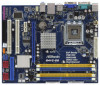
www.asrock.com/support/index.asp 1.1 Package Contents ASRock G41C-GS / G41C-S Motherboard (Micro ATX Form Factor: 9.6-in x 7.8-in, 24.4 cm x 19.8 cm) ASRock G41C-GS / G41C-S Quick Installation Guide ASRock G41C-GS / G41C-S Support CD Two Serial ATA (SATA) Data Cables (Optional) One I/O Panel Shield - ASRock G41C-GS | User Manual - Page 6
Specifications Platform CPU Chipset Memory Expansion Slot Graphics Audio LAN Rear Panel I/O - Micro ATX Form Factor: 9.6-in x 7.8-in, 24.4 cm x 19.8 cm - LGA 775 for Intel® CoreTM 2 Extreme / CoreTM 2 Quad / CoreTM 2 Duo / Pentium® Dual Core / Celeron® Dual Core / Celeron®, supporting Penryn Quad - ASRock G41C-GS | User Manual - Page 7
connector - 1 x Print port header - CPU/Chassis/Power FAN connector - 24 pin ATX power connector - 4 pin 12V power connector - Front panel audio connector - 2 x USB 2.0 headers (support 4 USB 2.0 ports) (see CAUTION 8) - 8Mb AMI BIOS - AMI Legal BIOS - Supports "Plug and Play" - ACPI 1.1 Compliance - ASRock G41C-GS | User Manual - Page 8
-CPU and DDR3 1333 memory module on this motherboard, you need to adjust the jumper. Please refer to page 22 for proper jumper settings. 5. Due to the operating system limitation, the actual memory size may be less than 4GB for the reservation for system usage under Windows® 7 / VistaTM / XP - ASRock G41C-GS | User Manual - Page 9
8. Power Management for USB 2.0 works fine under Microsoft® Windows® 7 64-bit / 7 / VistaTM 64-bit / VistaTM / XP 64-bit / XP SP1 or SP2. 9. It is a user-friendly ASRock overclocking tool which allows you to surveil your system by hardware monitor function and overclock your hardware devices to get - ASRock G41C-GS | User Manual - Page 10
under 1.00W in off mode condition. To meet EuP standard, an EuP ready motherboard and an EuP ready power supply are required. According to Intel's suggestion, the EuP ready power supply must meet the standard of 5v standby power efficiency is higher than 50% under 100 mA current consumption. For EuP - ASRock G41C-GS | User Manual - Page 11
(PCIE1) 25 FSB1 Jumper 9 Power Fan Connector (PWR_FAN1) 26 PCI Express x1 Slot (PCIE2) 10 Chassis Fan Connector (CHA_FAN1) 27 EUP Audio Jumper (EUP_AUDIO1) 11 IDE1 Connector (IDE1, Blue) 28 EUP LAN Jumper (EUP_LAN1) 12 Third SATAII Connector (SATAII_3; Red) 29 Front Panel Audio Header 13 - ASRock G41C-GS | User Manual - Page 12
function, you need to connect a front panel audio cable to the front panel audio header. After restarting your computer, you will find "VIA HD Audio Deck" tool on your system. Please follow below instructions according to the OS you install. For Windows® XP / XP 64-bit OS: Please click "VIA - ASRock G41C-GS | User Manual - Page 13
function, you need to connect a front panel audio cable to the front panel audio header. After restarting your computer, you will find "VIA HD Audio Deck" tool on your system. Please follow below instructions according to the OS you install. For Windows® XP / XP 64-bit OS: Please click "VIA - ASRock G41C-GS | User Manual - Page 14
G41C-GS / G41C-S is a Micro ATX form factor (9.6" x 7.8", 24.4 x 19.8 cm) motherboard. Before you install the motherboard, study the configuration of your chassis to ensure that the motherboard fits into it. Make sure to unplug the power cord before installing or removing the motherboard - ASRock G41C-GS | User Manual - Page 15
For the installation of Intel 775-LAND CPU, please follow the steps below. 775-Pin Socket Overview Before you insert the 775-LAND CPU into the socket, please check if the CPU surface is unclean or if there is any bent pin on the socket. Do not force to insert the CPU into the socket if - ASRock G41C-GS | User Manual - Page 16
CPU is within the socket and properly mated to the orient keys. Step 3. Remove PnP Cap (Pick and Place Cap): Use your left hand index finger and thumb to support PnP cap. 2. This cap must be placed if returning the motherboard for after service. Step 4. Close the socket: Step 4-1. Rotate the load - ASRock G41C-GS | User Manual - Page 17
Heatsink This motherboard is equipped with 775-Pin socket that supports Intel 775-LAND CPU. Please adopt the type of heatsink and cooling fan compliant with Intel 775-LAND CPU to dissipate heat. Before you installed the heatsink, you need to spray thermal interface material between the CPU and the - ASRock G41C-GS | User Manual - Page 18
motherboard provides two 240-pin DDR2 (Double Data Rate 2) DIMM slots and two 240-pin DDR3 (Double Data Rate 3) DIMM slots, and supports Slot) SS DS 1. If you want to install two memory modules, for optimal compatibility and reliability, it is recommended to install them in the slots of the same - ASRock G41C-GS | User Manual - Page 19
Installing a DIMM Please make sure to disconnect power supply before adding or removing DIMMs or the system break The DIMM only fits in one correct orientation. It will cause permanent damage to the motherboard and the DIMM if you force the DIMM into the slot at incorrect orientation. Step - ASRock G41C-GS | User Manual - Page 20
Slots (PCI and PCI Express Slots) There are 2 PCI slots and 2 PCI Express slots on this motherboard. PCI slots: PCI slots are used to install expansion cards that have the 32-bit PCI interface. PCIE slots: PCIE1 (PCIE x16 slot) is used for PCI Express cards with x16 lane width graphics cards. PCIE2 - ASRock G41C-GS | User Manual - Page 21
. EUP LAN / EUP Audio Jumper (EUP_LAN1, 3-pin jumper, see p.11 No. 28) (EUP_AUDIO1, 3-pin jumper, see p.11 No. 27) EUP_LAN1 EUP_AUDIO1 Default (Enable EuP) Note: EUP_LAN and EUP_AUDIO jumper design decreases the power consumption of this motherboard to meet EuP standard. With an ASRock EuP ready - ASRock G41C-GS | User Manual - Page 22
FSB1 Jumper (FSB1, 3-pin jumper, see p.11 No. 25) FSB1 Default If you adopt FSB1333-CPU and DDR3 1333 memory module on this motherboard, you need to adjust the jumper. Please short pin2, pin3 for FSB1 jumper. Otherwise, the CPU and memory module may not work properly on this motherboard. Please - ASRock G41C-GS | User Manual - Page 23
on the motherboard. USB 2.0 Audio supports Jack Sensing, but the panel wire on the chassis must support HDA to function correctly. Please follow the instruction in our manual and chassis manual to install your system. 2. If you use AC'97 audio panel, please install it to the front panel audio - ASRock G41C-GS | User Manual - Page 24
(Quiet Fan) support, the 3-Pin CPU fan still can work successfully even without the fan speed control function. If you plan to connect the 3-Pin CPU fan to the CPU fan connector on this motherboard, please connect it to Pin 1-3. Pin 1-3 Connected 3-Pin Fan Installation ATX Power Connector 24 (24 - ASRock G41C-GS | User Manual - Page 25
ATA features. Please visit HITACHI's website for details: http://www.hitachigst.com/hdd/support/download.htm The above examples are just for your reference. For different SATAII hard disk products of different vendors, the jumper pin setting methods may not be the same. Please visit the vendors - ASRock G41C-GS | User Manual - Page 26
drivers compatible to your system can be auto-detected and listed on the support CD driver page. Please follow the order from up to bottom side to install those required drivers. Therefore, the drivers you install can work properly. 2 . 1 2 Untied Overclocking Technology This motherboard supports - ASRock G41C-GS | User Manual - Page 27
motherboard stores the BIOS SETUP UTILITY. You may run the BIOS SETUP UTILITY when you start up the computer. Please press or during the Power-On-Self-Test (POST) to enter the BIOS set up overclocking features Advanced To set up the advanced BIOS features H/W Monitor To display current - ASRock G41C-GS | User Manual - Page 28
When you enter the BIOS SETUP UTILITY, the Main screen will appear and display the system overview. G41C-GS BIOS SETUP UTILITY Main field. BIOS Version : G41C-GS P1.00 Processor Type : Intel (R) Core (TM) 2 Duo CPU E8200 @ 2.66GHz (64bit) Processor Speed : 2666MHz Microcode Update : 10676/ - ASRock G41C-GS | User Manual - Page 29
12/01/2009] Use [Enter], [TAB] or [SHIFT-TAB] to select a field. BIOS Version : G41C-S P1.00 Processor Type : Intel (R) Core (TM) 2 Duo CPU E8200 @ 2.66GHz (64bit) Processor Speed : 2666MHz Microcode Update : 10676/60C Cache Size : 6144KB Total Memory DDRII1 DDRII2 DDR3_1 DDR3_2 : 2048MB - ASRock G41C-GS | User Manual - Page 30
Timing Configuration Ratio CMOS Setting 8 Intel (R) SpeedStep (tm) tech. Overclock Mode CPU Frequency (MHz) PCIE Frequency (MHz) [Auto] [8] [Auto] [Auto] [333] [100] If you adopt DDR3 1333 pls. adjust jumper set MB before apply it. For FSB1333 CPU: FSB1 = 2-3 DRAM Voltage NB Voltage VTT - ASRock G41C-GS | User Manual - Page 31
Defaults Save and Exit Exit v02.54 (C) Copyright 1985-2003, American Megatrends, Inc. DRAM tCL This controls the number of DRAM clocks for TCL. For DDR3, Min: 5. Max: 10. For DDR2, Min: 3. Max: 7. The default value is [Auto]. DRAM tRCD This controls the number of DRAM clocks for TRCD. Min: 3. Max - ASRock G41C-GS | User Manual - Page 32
hidden if the current CPU does not support Intel (R) SpeedStep(tm) tech.. Please note that enabling this function may reduce CPU voltage and lead to system stability or compatibility issue with some power supplies. Please set this item to [Disable] if above issue occurs. Overclock Mode Use this to - ASRock G41C-GS | User Manual - Page 33
Would you like to save current setting user defaults? In this option, you are allowed to load and save three user defaults according to your own requirements. 33 - ASRock G41C-GS | User Manual - Page 34
in below sections may cause system to malfunction. CPU Configuration Chipset Configuration ACPI Configuration Storage Configuration PCIPnP Configuration Floppy Configuration SuperIO Configuration USB Configuration BIOS Update Utility ASRock Instant Flash Select Screen Select Item Enter Go to - ASRock G41C-GS | User Manual - Page 35
Halt State (C1). The C1 state is supported through the native processor instructions HLT and MWAIT and requires no hardware support from the chipset. In the C1 power state, the processor maintains the context of the system caches. Intel (R) Virtualization tech. When this option is set to [Enabled - ASRock G41C-GS | User Manual - Page 36
] if using Microsoft® Windows® XP, or Linux kernel version 2.4.18 or higher. This option will be hidden if the installed CPU does not support Hyper-Threading technology. Intel (R) SpeedStep(tm) tech. Intel (R) SpeedStep(tm) tech. is Intel's new power saving technology. Processor can switch between - ASRock G41C-GS | User Manual - Page 37
Energy Saver Primary Graphics Adapter Shared Memory PAVP Mode DVMT Mode Select DVMT/FIXED Memory [Disabled] [PCI] [Auto] [Disabled] [DVMT Mode] [Maximum DVMT] Onboard HD Audio Front Panel OnBoard Lan [Auto] [Enabled] [Enabled] +F1 F9 F10 ESC Select Screen Select Item Change Option General - ASRock G41C-GS | User Manual - Page 38
DRAM CH0 G3 (Control2) This controls the number of DRAM CH0 G3 (Control2). Min: 1. Max: 15. The default value is [Auto]. DRAM CH0 G4 (Clocks1) This controls the number of DRAM CH0 G4 (Clocks1). Min: 1. Max: 15. The default value is [Auto]. DRAM CH0 G5 (Clocks2) This controls the number of DRAM CH0 - ASRock G41C-GS | User Manual - Page 39
DRAM DLL SKEW Configuration BIOS SETUP UTILITY Advanced DRAM DLL SKEW Settings DRAM CH0 CLKSET0 SKEW Info:0-0-0-0-0-0 DRAM CH0 CLKSET0 SKEW [Auto] DRAM CH0 CLKSET1 SKEW Info:0-0-0-0-0-0 DRAM CH0 CLKSET1 - ASRock G41C-GS | User Manual - Page 40
DRAM CH1 CMD SKEW This controls the number of DRAM CH1 CMD SKEW. The default value is [Auto]. DRAM CH1 CTRL0 SKEW This controls the number of DRAM CH1 CTRL0 SKEW. The default value is [Auto]. DRAM CH1 CTRL1 SKEW This controls the number of DRAM CH1 CTRL1 SKEW. The default value is [Auto]. DRAM CH1 - ASRock G41C-GS | User Manual - Page 41
the new graphics feature in Intel® 4 Series Express chipset family to support increased content protection and Audio Select [Auto], [Enabled] or [Disabled] for the onboard HD Audio feature. If you select [Auto], the onboard HD Audio will be disabled when PCI Sound Card is plugged. Front Panel - ASRock G41C-GS | User Manual - Page 42
BIOS SETUP UTILITY Advanced ACPI Configuration Suspend To RAM Restore on AC/Power Loss Ring-In Power On PCI Devices Power On PS / 2 Keyboard Power On RTC Alarm Power On ACPI HPET Table [Disabled] [Power the OS supports it. If you set this item to [Disabled], the function "Repost Video on STR - ASRock G41C-GS | User Manual - Page 43
motherboard to submit Windows® VistaTM certification. 3.4.4 Storage Configuration BIOS Compatible] when Legacy OS (MS-DOS, Win NT) device is used. Set [Enhanced] when Native OS (Win2000 / XP not work. Because Intel® ICH7 south bridge only supports four IDE devices under legacy OS (Windows NT), you - ASRock G41C-GS | User Manual - Page 44
" as the example in the following instruction. BIOS SETUP UTILITY Advanced Primary IDE Master Device :ST340014A :40.0 GB :Supported :16Sectors :4 :MultiWord DMA-2 :Ultra DMA-5 :Supported [Auto] [Auto] [ for a hard disk > 512 MB under DOS and Windows; for Netware and UNIX user, select [Disabled] to - ASRock G41C-GS | User Manual - Page 45
DMA capability allows the improved transfer-speed and data-integrity for compatible IDE devices. S.M.A.R.T. Use this item to enable or disable BIOS SETUP UTILITY Advanced Advanced PCI / PnP Settings PCI Latency Timer PCI IDE BusMaster [32] [Enabled] Value in units of PCI clocks for PCI device - ASRock G41C-GS | User Manual - Page 46
3.4.6 Floppy Configuration In this section, you may configure the type of your floppy drive. BIOS SETUP UTILITY Advanced Floppy Configuration Floppy A [1.44 MB 312"] Select the type of floppy drive connected to the system. +F1 F9 F10 ESC Select Screen - ASRock G41C-GS | User Manual - Page 47
SETUP UTILITY Advanced Configure Super IO Chipset Serial Port Address Parallel Port Address Parallel Port Mode EPP Version ECP Mode DMA Channel Parallel Port IRQ [3F8 / IRQ4] [378] [ECP + EPP] [1.9] [DMA3] [IRQ7] Allow BIOS to Enable or Disable Floppy Controller. +F1 F9 F10 ESC Select Screen - ASRock G41C-GS | User Manual - Page 48
these four options: [Enabled] - Enables support for legacy USB. [Auto] - Enables legacy support if USB devices are connected. [Disabled] - USB devices are not allowed to use under legacy OS and BIOS setup when [Disabled] is selected. If you have USB compatibility issue, it is recommended to select - ASRock G41C-GS | User Manual - Page 49
, motherboard temperature, CPU fan speed, chassis fan speed, and the critical voltage. BIOS SETUP UTILITY Main OC Tweaker Advanced H/W Monitor Boot Security Exit Hardware Health Event Monitoring CPU Temperature M / B Temperature CPU Fan Speed Chassis Fan Speed Power Fan Speed Vcore + 3.30V - ASRock G41C-GS | User Manual - Page 50
F10 Save and Exit ESC Exit v02.54 (C) Copyright 1985-2005, American Megatrends, Inc. 3.6.1 Boot Settings Configuration BIOS SETUP UTILITY Boot Boot Settings Configuration Full Screen Logo AddOn ROM Display Boot Logo Boot From Onboard LAN Bootup Num-Lock [Enabled] [Enabled] [Auto] [Disabled] [On - ASRock G41C-GS | User Manual - Page 51
the option "Full Screen Logo". Configuration options: [Auto], [EuP], [Scenery] and [ASRock]. The default value is [Auto]. Currently, the option [Auto] is set to system. For the user password, you may also clear it. BIOS SETUP UTILITY Main OC Tweaker Advanced H/W Monitor Boot Security Exit Security - ASRock G41C-GS | User Manual - Page 52
Load BIOS Defaults Load Performance Setup Default (IDE/SATA) Load Power Saving Setup compatible with all system configurations. If system boot failure occurs after loading, please resume optimal default settings. F5 key can be used for this operation. Load Power Saving Setup Default Load power - ASRock G41C-GS | User Manual - Page 53
CD that came with the motherboard contains necessary drivers and useful utilities that enhance the motherboard features. 4.2.1 Running The Support CD To begin using the support CD, insert the CD into your CD-ROM drive. The CD automatically displays the Main Menu if "AUTORUN" is enabled in your
-
 1
1 -
 2
2 -
 3
3 -
 4
4 -
 5
5 -
 6
6 -
 7
7 -
8
-
9
-
10
-
11
-
12
-
13
-
14
-
15
-
16
-
17
-
18
-
19
-
20
-
21
-
22
-
23
-
24
-
25
-
26
-
27
-
28
-
29
-
30
-
31
-
32
-
33
-
34
-
35
-
36
-
37
-
38
-
39
-
40
-
41
-
42
-
43
-
44
-
45
-
46
-
47
-
48
-
49
-
50
-
51
-
52
-
53
 |
 |
1
G41C-GS / G41C-S
User Manual
Version 1.0
Published December 2009
Copyright©2009 ASRock INC. All rights reserved.