ASRock G41C-GS Quick Installation Guide
ASRock G41C-GS Manual
 |
View all ASRock G41C-GS manuals
Add to My Manuals
Save this manual to your list of manuals |
ASRock G41C-GS manual content summary:
- ASRock G41C-GS | Quick Installation Guide - Page 1
appear in this guide. With respect to the contents of this guide, ASRock does not provide warranty of any kind, either expressed or implied, including ASRock Website: http://www.asrock.com Published December 2009 Copyright©2009 ASRock INC. All rights reserved. 1 ASRock G41C-GS / G41C-S Motherboard - ASRock G41C-GS | Quick Installation Guide - Page 2
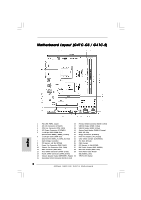
(PCIE1) 25 FSB1 Jumper 9 Power Fan Connector (PWR_FAN1) 26 PCI Express x1 Slot (PCIE2) 10 Chassis Fan Connector (CHA_FAN1) 27 EUP Audio Jumper (EUP_AUDIO1) 11 IDE1 Connector (IDE1, Blue) 28 EUP LAN Jumper (EUP_LAN1) 12 Third SATAII Connector (SATAII_3; Red) 29 Front Panel Audio Header 13 - ASRock G41C-GS | Quick Installation Guide - Page 3
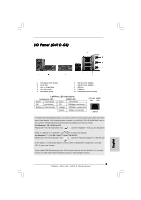
front panel audio cable to the front panel audio header. After restarting your computer, you will find "VIA HD Audio Deck" tool on your system. Please follow below instructions according to the OS you install. For Windows® XP / XP Speaker function. 3 ASRock G41C-GS / G41C-S Motherboard English - ASRock G41C-GS | Quick Installation Guide - Page 4
front panel audio cable to the front panel audio header. After restarting your computer, you will find "VIA HD Audio Deck" tool on your system. Please follow below instructions according to the OS you install. For Windows® XP / XP Speaker function. 4 ASRock G41C-GS / G41C-S Motherboard English - ASRock G41C-GS | Quick Installation Guide - Page 5
ASRock G41C-GS / G41C-S Motherboard (Micro ATX Form Factor: 9.6-in x 7.8-in, 24.4 cm x 19.8 cm) ASRock G41C-GS / G41C-S Quick Installation Guide ASRock G41C-GS / G41C-S Support CD Two Serial ATA (SATA) Data Cables (Optional) One I/O Panel Shield English 5 ASRock G41C-GS / G41C-S Motherboard - ASRock G41C-GS | Quick Installation Guide - Page 6
Specifications Platform CPU Chipset Memory Expansion Slot Graphics Audio LAN Rear Panel I/O - Micro ATX Form Factor: 9.6-in x 7.8-in, 24.4 cm x 19.8 cm - LGA 775 for Intel® CoreTM 2 Extreme / CoreTM 2 Quad / CoreTM 2 Duo / Pentium® Dual Core / Celeron® Dual Core / Celeron®, supporting Penryn Quad - ASRock G41C-GS | Quick Installation Guide - Page 7
- 1 x Print port header BIOS Feature - CPU/Chassis/Power FAN connector - 24 pin ATX power connector - 4 pin 12V power connector - Front panel audio connector - 2 x USB 2.0 headers (support 4 USB 2.0 ports) (see CAUTION 8) - 8Mb AMI BIOS - AMI Legal BIOS - Supports "Plug and Play" - ACPI - ASRock G41C-GS | Quick Installation Guide - Page 8
hard disk to SATAII connector, please read the "SATAII Hard Disk Setup Guide" on page 25 of "User Manual" in the support CD to adjust your SATAII hard disk drive to SATAII mode. You can also connect SATA hard disk to SATAII connector directly. 8 ASRock G41C-GS / G41C-S Motherboard English - ASRock G41C-GS | Quick Installation Guide - Page 9
system, please check if the CPU fan on the motherboard functions properly and unplug the power cord, then plug it back again. To improve heat dissipation, remember to spray thermal grease between the CPU and the heatsink when you install the PC system. 9 ASRock G41C-GS / G41C-S Motherboard English - ASRock G41C-GS | Quick Installation Guide - Page 10
, the EuP ready power supply must meet the standard of 5v standby power efficiency is higher than 50% under 100 mA current consumption. For EuP ready power supply selection, we recommend you checking with the power supply manufacturer for more details. 10 ASRock G41C-GS / G41C-S Motherboard English - ASRock G41C-GS | Quick Installation Guide - Page 11
you insert the 775-LAND CPU into the socket, please check if the CPU surface is unclean or if there is any bent pin on the socket. Do not force to insert the CPU into the socket if above situation is found. Otherwise, the CPU will be seriously damaged. 11 ASRock G41C-GS / G41C-S Motherboard English - ASRock G41C-GS | Quick Installation Guide - Page 12
100 degrees. Step 2. Insert the 775-LAND CPU: Step 2-1. Hold the CPU by the edges where are marked with support the load plate edge, engage PnP cap with right hand thumb and peel the cap from the socket while pressing on center of PnP cap to assist in removal. 12 ASRock G41C-GS / G41C-S Motherboard - ASRock G41C-GS | Quick Installation Guide - Page 13
, the heatsink cannot be secured on the motherboard. Step 5. Step 6. Connect fan header with the CPU fan connector on the motherboard. Secure excess cable with tie-wrap to ensure cable does not interfere with fan operation or contact other components. 13 ASRock G41C-GS / G41C-S Motherboard - ASRock G41C-GS | Quick Installation Guide - Page 14
optimal compatibility and DDR3 memory module into DDR2 slot or install a DDR2 memory module into DDR3 slot; otherwise, this motherboard and DIMM may be damaged. 4. DDR2 and DDR3 memory modules cannot be installed on this motherboard at the same time. English 14 ASRock G41C-GS / G41C-S Motherboard - ASRock G41C-GS | Quick Installation Guide - Page 15
to disconnect power supply before motherboard and the DIMM if you force the DIMM into the slot at incorrect orientation. Step 3. Firmly insert the DIMM into the slot until the retaining clips at both ends fully snap back in place and the DIMM is properly seated. 15 ASRock G41C-GS / G41C-S Motherboard - ASRock G41C-GS | Quick Installation Guide - Page 16
the bracket facing the slot that you intend to use. Keep the screws for later use. Step 3. Align the card connector with the slot and press firmly until the card is completely seated on the slot. Step 4. Fasten the card to the chassis with screws. 16 ASRock G41C-GS / G41C-S Motherboard English - ASRock G41C-GS | Quick Installation Guide - Page 17
want to disable this power saving function, you may short pin2 and pin3. Please be noticed that when EUP_LAN jumper is set to enabled, the Wake-On-LAN function under S3 (Suspend to RAM), S4 (Suspend to Disk), and S5 (Soft Off) will be disabled. (Disable EuP) 17 ASRock G41C-GS / G41C-S Motherboard - ASRock G41C-GS | Quick Installation Guide - Page 18
. 12) (SATAII_4: see p.2, No. 13) SATAII_1 SATAII_2 SATAII_3 SATAII_4 These four Serial ATAII (SATAII) connectors support SATAII or SATA hard disk for internal storage devices. The current SATAII interface allows up to 3.0 Gb/s data transfer rate. 18 ASRock G41C-GS / G41C-S Motherboard English - ASRock G41C-GS | Quick Installation Guide - Page 19
and OUT_RET are for HD audio panel only. You don't need to connect them for AC'97 audio panel. E. Enter BIOS Setup Utility. Enter Advanced Settings, and then select Chipset Configuration. Set the Front Panel Control option from [Auto] to [Enabled]. 19 ASRock G41C-GS / G41C-S Motherboard English - ASRock G41C-GS | Quick Installation Guide - Page 20
1 ATX 12V Connector Please note that it is necessary (4-pin ATX12V2) to connect a power supply with (see p.2 No. 2) ATX 12V plug to this connector so that it can provides sufficient power. Failing to do so will cause the failure to power up. 20 ASRock G41C-GS / G41C-S Motherboard English - ASRock G41C-GS | Quick Installation Guide - Page 21
overclocking, but PCI / PCIE buses are in the fixed mode so that FSB can operate under a more stable overclocking environment. Please refer to the warning on page 8 for the possible overclocking risk before you apply Untied Overclocking Technology. English 21 ASRock G41C-GS / G41C-S Motherboard - ASRock G41C-GS | Quick Installation Guide - Page 22
drive. It will display the Main Menu automatically if "AUTORUN" is enabled in your computer. If the Main Menu does not appear automatically, locate and doubleclick on the file "ASSETUP.EXE" from the BIN folder in the Support CD to display the menus. 22 ASRock G41C-GS / G41C-S Motherboard English - ASRock G41C-GS | Quick Installation Guide - Page 23
Kartoninhalt ASRock G41C-GS / G41C-S Motherboard (Micro ATX-Formfaktor: 24.4 cm x 19.8 cm; 9.6 Zoll x 7.8 Zoll) ASRock G41C-GS / G41C-S Schnellinstallationsanleitung ASRock G41C-GS / G41C-S_ Support-CD Zwei Seriell-ATA- (SATA) Datenkabel (Option) Ein I/O Shield 23 ASRock G41C-GS / G41C-S Motherboard - ASRock G41C-GS | Quick Installation Guide - Page 24
1.2 Spezifikationen Plattform CPU Chipsatz Speicher Erweiterungssteckplätze Onboard-VGA Audio LAN - Micro ATX-Formfaktor: 24.4 cm x 19.8 cm; 9.6 Zoll x 7.8 Zoll - LGA 775 für Intel® CoreTM 2 Extreme / CoreTM 2 Quad / CoreTM 2 Duo / Pentium® Dual Core / Celeron® Dual Core / Celeron® unterstützt - ASRock G41C-GS | Quick Installation Guide - Page 25
- Intelligent Energy Saver (Intelligente Energiesparfunktion) (siehe VORSICHT 10) - Sofortstart - ASRock Instant Flash (siehe VORSICHT 11) - ASRock OC DNA (siehe VORSICHT 12) - Hybrid Booster: - Schrittloser CPU-Frequenz-Kontrolle (siehe VORSICHT 13) 25 ASRock G41C-GS / G41C-S Motherboard - ASRock G41C-GS | Quick Installation Guide - Page 26
. 3. Dieses Motherboard unterstützt Dual-Kanal-Speichertechnologie. Vor Implementierung der Dual-Kanal-Speichertechnologie müssen Sie die Installationsanleitung für die Speichermodule auf Seite 14 zwecks richtiger Installation gelesen haben. 26 ASRock G41C-GS / G41C-S Motherboard Deutsch - ASRock G41C-GS | Quick Installation Guide - Page 27
Power Management für USB 2.0 arbeitet unter Microsoft® Windows® 7 64-Bit / 7 / VistaTM 64-Bit / VistaTM / XP 64-Bit / XP SP1 oder SP2 einwandfrei. 9. Es ist ein benutzerfreundlicher ASRock Energy Saver. ASRock-Website: http://www.asrock.com Deutsch 27 ASRock G41C-GS / G41C-S Motherboard - ASRock G41C-GS | Quick Installation Guide - Page 28
bitte, ob der CPU-Lüfter am Motherboard richtig funktioniert, und stecken Sie bitte den Stromkabelstecker aus und dann wieder ein. Um die Wärmeableitung zu verbessern, bitte nicht vergessen, etwas Wärmeleitpaste zwischen CPU und Kühlkörper zu sprühen. 28 ASRock G41C-GS / G41C-S Motherboard Deutsch - ASRock G41C-GS | Quick Installation Guide - Page 29
zu entsprechen, sind ein EuP-fähiges Motherboard und eine EuP-fähige Stromversorgung erforderlich. Gemäß einer Empfehlung von Intel muss eine EuP-fähige Stromversorgung dem Standard Ihnen, weitere Details beim Hersteller der Stromversorgung abzufragen. 29 ASRock G41C-GS / G41C-S Motherboard Deutsch - ASRock G41C-GS | Quick Installation Guide - Page 30
Audio-Jumper (EUP_LAN1, 3-pol. Jumper, siehe Seite 2, Nr. 28) (EUP_AUDIO1, 3-pol. Jumper, siehe Seite 2, Nr. 27) Standard (EuP aktivieren) Deutsch Hinweis: Das Jumper-Design EUP_LAN und EUP_AUDIO verringert den Energieverbrauch dieses Motherboards 1 und Pin 2 30 ASRock G41C-GS / G41C-S Motherboard - ASRock G41C-GS | Quick Installation Guide - Page 31
deaktivieren) FSB1-Jumper (FSB1, 3-pol. Jumper, siehe Seite 2, Nr. 25) Default-Einstellung Wenn Sie die FSB1333-CPU und DDR3 1333 Speicher auf diesem Motherboard übernehmen, müssen Sie Jumper umsetzen. Schliesen Sie Kontaktstift 2, Kontaktstift 3kurz für FSB1-Jumper. Andernfalls wird die CPU und - ASRock G41C-GS | Quick Installation Guide - Page 32
(Option) USB 2.0-Header (9- Audio auf der Gehäusevorderseite (9-Pin HD_AUDIO1) (siehe S.2 - No. 29) Dieses Interface zu einem Audio-Panel auf der Vorderseite Ihres Gehäuses, ermöglicht Ihnen eine bequeme Anschlussmöglichkeit und Kontrolle über Audio-Geräte. 32 ASRock G41C-GS / G41C-S Motherboard - ASRock G41C-GS | Quick Installation Guide - Page 33
der Front- 10) (3-pin PWR_FAN1) (siehe S.2, No. 9) Schließen Sie den Gehäuselautsprecher an diesen Header an. Verbinden Sie die Lüfterkabel mit den Lüfteranschlüssen, wobei der schwarze Draht an den Schutzleiterstift angeschlossenwird. Deutsch 33 ASRock G41C-GS / G41C-S Motherboard - ASRock G41C-GS | Quick Installation Guide - Page 34
dreipoligen CPU-Lüfter an den CPU-Lüferanschluss dieses Motherboards anschließ ATX 12-Volt-Stecker mit diesem Anschluss verbinden müssen, damit ausreichend Strom geliefert werden kann. Andernfalls reicht der Strom nicht aus, das System zu starten. Deutsch 34 ASRock G41C-GS / G41C-S Motherboard - ASRock G41C-GS | Quick Installation Guide - Page 35
der Support-CD, um die Menüs aufzurufen. Das Setup-Programm soll es Ihnen so leicht wie möglich machen. Es ist menügesteuert, d.h. Sie können in den verschiedenen Untermenüs Ihre Auswahl treffen und die Programme werden dann automatisch installiert. Deutsch 35 ASRock G41C-GS / G41C-S Motherboard - ASRock G41C-GS | Quick Installation Guide - Page 36
re ASRock G41C-GS / G41C-S (Facteur de forme Micro ATX: 9.6 pouces x 7.8 pouces, 24.4 cm x 19.8 cm) Guide d'installation rapide ASRock G41C-GS / G41C-S CD de soutien ASRock G41C-GS / G41C-S Deux câble de données Serial ATA (SATA) (en option) Un écran I/O 36 ASRock G41C-GS / G41C-S Motherboard Fran - ASRock G41C-GS | Quick Installation Guide - Page 37
1.2 Spécifications Format CPU Chipsets Mémoire Slot d'extension VGA sur carte Audio LAN - Facteur de forme Micro ATX : 9.6 pouces x 7.8 pouces, 24.4 cm x 19.8 cm - LGA 775 pour Intel® CoreTM 2 Extreme / CoreTM 2 Quad / CoreTM 2 Duo / Pentium® Dual Core / Celeron® Dual Core / Celeron® acceptant les - ASRock G41C-GS | Quick Installation Guide - Page 38
de CPU/Châssis/Ventilateur - br. 24 connecteur d'alimentation ATX - br. 4 connecteur d'alimentation 12V ATX - Connecteur audio panneau avant - 2 x en-tête USB 2.0 (accepte 4 ports USB 2.0) (voir ATTENTION 8) BIOS - 8Mb BIOS AMI - BIOS AMI - Support du "Plug and Play" - Compatible pour - ASRock G41C-GS | Quick Installation Guide - Page 39
3. Cette carte mère supporte la Technologie de Mémoire à Canal Double. Avant d'intégrer la Technologie de Mémoire à Canal Double, assurezvous de bien lire le guide d'installation des modules mémoire en page 14 pour réaliser une installation correcte. Français 39 ASRock G41C-GS / G41C-S Motherboard - ASRock G41C-GS | Quick Installation Guide - Page 40
l'USB 2.0 fonctionne bien sous Microsoft® Windows® 7 64-bit / 7 / VistaTM 64-bit/ VistaTM / XP 64-bit / XP SP1; SP2. 9. Il s'agit d'un usage facile ASRock overclocking outil d'Intelligent Energy Saver. Site Web ASRock : http://www.asrock.com Français 40 ASRock G41C-GS / G41C-S Motherboard - ASRock G41C-GS | Quick Installation Guide - Page 41
Windows®. Com este utilitário, poderá premir a tecla durante o teste de arranque POST ou premir a tecla para exibir o menu de configuração do BIOS para aceder ao ASRock le CPU le . Selon les suggestions d'Intel', l'alimentation électrique EuP ASRock G41C-GS / G41C-S Motherboard Français - ASRock G41C-GS | Quick Installation Guide - Page 42
aux périphériques PS/2 ou USB de réveiller le système. restauré le CMOS. Cavalier EUP LAN / EUP Audio (EUP_LAN1, cavalier à 3 broches, voir p.2 codes pin2 et pin3. Veuillez noter que lorsque le cavalier EUP_LAN est activé, la fonction de réveil Wake-On- 42 ASRock G41C-GS / G41C-S Motherboard - ASRock G41C-GS | Quick Installation Guide - Page 43
ée. (Désactiver EuP) Cavalier FSB1 (FSB1, cavalier à 3 broches, voir p.2 N° 25) Par défaut Si vous adoptez un CPU FSB1333 et Mémoire DDR3 1333 sur cette carte mère reporter aux instructions du fabricant de votre IDE périphérique pour les détails. 43 ASRock G41C-GS / G41C-S Motherboard Français - ASRock G41C-GS | Quick Installation Guide - Page 44
es Série ATA (SATA) (en option) En-tête USB 2.0 (USB6_7 br.9) (voir p.2 No. 17) audio panneau avant (HD_AUDIO1 br. 9) (voir p.2 No. 29) C'est une interface pour un câble audio en façade qui permet le branchement et le contrôle commodes de périphériques audio. 44 ASRock G41C-GS / G41C-S Motherboard - ASRock G41C-GS | Quick Installation Guide - Page 45
de vitesse du ventilateur. Si vous prévoyez de connecter le ventilateur de CPU à 3 broches au connecteur du ventilateur de CPU sur cette carte mère, veuillez le connecter aux broches 1-3. Installation de ventilateur à 3 broches Broches 1-3 connectées 45 ASRock G41C-GS / G41C-S Motherboard Français - ASRock G41C-GS | Quick Installation Guide - Page 46
électrique ainsi qu'aux broches 1 et 13. 24 13 20-Installation de l'alimentation électrique ATX 12 1 Connecteur ATX 12V (ATX12V1 br.4) (voir p.2 No. 2) Veuillez connecter une unité d'alimentation électrique ATX 12V sur ce connecteur. Français 46 ASRock G41C-GS / G41C-S Motherboard - ASRock G41C-GS | Quick Installation Guide - Page 47
BIOS, veuillez consulter le Guide de l'utilisateur (fichier PDF) dans le CD technique. 3. Informations sur le CD de support Cette carte mère supporte divers systèmes d'exploitation Microsoft® Windows®: 7 / 7 64 bits / VistaTM / VistaTM 64 bits / XP / XP çais 47 ASRock G41C-GS / G41C-S Motherboard - ASRock G41C-GS | Quick Installation Guide - Page 48
Scheda madre ASRock G41C-GS / G41C-S (Micro ATX Form Factor: 9.6-in x 7.8-in, 24.4 cm x 19.8 cm) Guida di installazione rapida ASRock G41C-GS / G41C-S CD di supporto ASRock G41C-GS / G41C-S Due cavo dati Serial ATA (SATA) (Opzionale) Un I/O Shield 48 ASRock G41C-GS / G41C-S Motherboard Italiano - ASRock G41C-GS | Quick Installation Guide - Page 49
a 2048x1536 @ 75Hz Audio - 5.1 Audio HD CH (VIA® VT1705 Audio Codec) LAN - G41C-GS Realtek PCIE x1 Gigabit LAN RTL8111DL, velocità 10/100/1000 Mb/s - G41C-S Realtek PCIE x1 LAN 8103EL / 8102EL, velocità 10/100 Mb/s - Supporta Wake-On-LAN 49 ASRock G41C-GS / G41C-S Motherboard Italiano - ASRock G41C-GS | Quick Installation Guide - Page 50
Boot - ASRock Instant Flash (vedi ATTENZIONE 11) - ASRock OC DNA (vedi ATTENZIONE 12) - Booster ibrido: - Stepless control per frequenza del processore (vedi ATTENZIONE 13) - ASRock U-COP (vedi ATTENZIONE 14) - Boot Failure Guard (B.F.G.) Italiano 50 ASRock G41C-GS / G41C-S Motherboard - ASRock G41C-GS | Quick Installation Guide - Page 51
1333 DDR3 800, DDR3 1066, DDR3 1333 DDR2 667, DDR2 800 1066 DDR3 800, DDR3 1066 DDR2 667, DDR2 800 800 DDR3 800 DDR2 667, DDR2 800 533 DDR3 800 DDR2 533 * I moduli di memoria DDR3 1333 funzioneranno in modalita' di sincronizzazione. Italiano 51 ASRock G41C-GS / G41C-S Motherboard - ASRock G41C-GS | Quick Installation Guide - Page 52
) o disco rigido; poi si può aggiornare il BIOS con pochi clic, senza preparare altri dischetti (dischi floppy) o altre complicate utilità Flash. Si prega di notare che l'unità Flash USB o il disco rigido devono usare il File System FAT32/16/ 12. 52 ASRock G41C-GS / G41C-S Motherboard Italiano - ASRock G41C-GS | Quick Installation Guide - Page 53
motherboard offre il controllo stepless, non si consiglia di effettuare l'overclocking. Frequenze del bus del processore scheda elettrica predisposti EuP. In base ai suggerimenti Intel l'alimentatore predisposto EuP deve soddisfare lo standard secondo cui ASRock G41C-GS / G41C-S Motherboard Italiano - ASRock G41C-GS | Quick Installation Guide - Page 54
funzione di risparmio energetico, è possibile accorciare il pin2 e il pin3. Quando il jumper EUP_LAN è impostato su abilitato, le funzioni Wake-OnLAN sotto S3 (sospendi su RAM), S4 (sospendi su disco), e S5 (Soft Off) verranno disabilitate. (Disabilita EuP) 54 ASRock G41C-GS / G41C-S Motherboard - ASRock G41C-GS | Quick Installation Guide - Page 55
Jumper FSB1 (FSB1, jumper a 3 pin, vedere p.2 N. 25) Predefinito Se su questa scheda madre si utilizza la CPU FSB1333 e momoria DDR3 1333, è necessario regolare i jumper. Cortocircuitare i pin2 e pin3 per i jumper di FSB1. In caso contrario la CPU 55 ASRock G41C-GS / G41C-S Motherboard Italiano - ASRock G41C-GS | Quick Installation Guide - Page 56
un pannello audio AC'97, installarlo nell'intestazione audio del pannello anteriore, come indicato di seguito: A. Collegare Mic_IN (MIC) a MIC2_L. B. Collegare Audio_R (RIN) a OUT2_R e Audio_L (LIN) ad OUT2_L. C. Collegare Ground (GND) a Ground (GND). 56 ASRock G41C-GS / G41C-S Motherboard Italiano - ASRock G41C-GS | Quick Installation Guide - Page 57
CPU su questa scheda madre, collegarla ai piedini 1-3. Piedini 1-3 collegati Installazione della ventola a 3 piedini Connettore alimentazione ATX (24-pin ATXPWR1) 24 (vedi p.2 Nr. 4) 12 Collegare la sorgente 13 d'alimentazione ATX a questo 1 connettore. 57 ASRock G41C-GS / G41C-S Motherboard - ASRock G41C-GS | Quick Installation Guide - Page 58
ATX a 20 pin 12 1 Connettore ATX 12V (4-pin ATX12V1) (vedi p.2 Nr. 2) È necessario collegare una alimentazione con spinotto da 12V ATX a questo connettore in modo che possa fornire energia sufficiente. In caso contrario l'unità non si avvia. Italiano 58 ASRock G41C-GS / G41C-S Motherboard - ASRock G41C-GS | Quick Installation Guide - Page 59
Manuale dell'Utente (PDF file) contenuto nel cd di supporto. 3. Software di supporto e informazioni su CD Questa scheda madre supporta vari sistemi operativi Microsoft® Windows®: 7 / 7 64-bit / VistaTM / VistaTM 64-bit / XP / XP visualizzare i menù. Italiano 59 ASRock G41C-GS / G41C-S Motherboard - ASRock G41C-GS | Quick Installation Guide - Page 60
Placa base ASRock G41C-GS / G41C-S (Factor forma Micro ATX: 24,4 cm x 19,8 cm, 9,6" x 7,8") Guía de instalación rápida de ASRock G41C-GS / G41C-S CD de soporte de ASRock G41C-GS / G41C-S Dos Cable de Datos Serial ATA (SATA) (Opcional) Una protección I/O 60 ASRock G41C-GS / G41C-S Motherboard Espa - ASRock G41C-GS | Quick Installation Guide - Page 61
ón Plataforma Procesador Chipset Memoria Ranuras de Expansión VGA OnBoard Audio LAN - Factor forma Micro ATX: 24,4 cm x 19,8 cm, 9,6" x 7,8" - LGA 775 para Intel® CoreTM 2 Extreme / CoreTM 2 Quad / CoreTM 2 Duo / Pentium® Doble Núcleo / Celeron® Doble Núcleo / Celeron® compatible con procesadores - ASRock G41C-GS | Quick Installation Guide - Page 62
- Conector de ventilador de CPU / chasis / alimentacion - 24-pin cabezal de alimentación ATX - 4-pin conector de ATX 12V power - Conector de audio de panel frontal - 2 x Conector USB 2.0 (compatible con 4 puertos USB 2.0) (vea ATENCIÓN 8) - 8Mb AMI BIOS - AMI legal BIOS - Soporta "Plug and Play - ASRock G41C-GS | Quick Installation Guide - Page 63
CPU / chasis / alimentacion - Ventilador silencioso para procesador - Monitor de Voltaje: +12V, +5V, +3.3V, Vcore OS - En conformidad con Microsoft® Windows® 7 / 7 64 bits / VistaTM / VistaTM 64 bits / XP / XP consulte página 36 del Manual del Usuario en el ASRock G41C-GS / G41C-S Motherboard - ASRock G41C-GS | Quick Installation Guide - Page 64
Power Management para USB 2.0 funciona bien bajo Microsoft® Windows® 7 64 bits / 7 / VistaTM 64 bits / VistaTM / XP 64 bits / XP SP1; SP2. 9. Es una herramienta de overclocking de ASRock Energy Saver. Sitio web de ASRock: http://www.asrock.com Español 64 ASRock G41C-GS / G41C-S Motherboard - ASRock G41C-GS | Quick Installation Guide - Page 65
BIOS y a la utilidad ASRock Instant Flash. Ejecute esta herramienta y guarde el archivo correspondiente al sistema BIOS nuevo en su unidad flash USB ventilador de la CPU de la placa base EuP. Según las directrices de Intel, una fuente de alimentación que ASRock G41C-GS / G41C-S Motherboard Español - ASRock G41C-GS | Quick Installation Guide - Page 66
jumper cap está colocado sobre estes 2 pins. Short Open Jumper Setting Descripción PS2_USB_PWR1 Ponga en cortocircuito pin 2, (vea p.2, N. 1) pin 3 para habilitar +5VSB (standby) para PS/2 o USB segundos usando un jumper cap. Conector de Audio EUP LAN / ASRock G41C-GS / G41C-S Motherboard - ASRock G41C-GS | Quick Installation Guide - Page 67
Suave) será desactivada. (Desactivar EuP) Puente FSB1 (FSB1, puente de 3 terminales, consulte la p. 2, Nº 25) Predeterminado Si usa la CPU FSB1333 y Memoria DDR3 1333 en esta placa base, necesitará ajustar dispositivo IDE para conocer los detalles. 67 ASRock G41C-GS / G41C-S Motherboard Español - ASRock G41C-GS | Quick Installation Guide - Page 68
que permite conectar cómodamente dispositivos de impresión. Conector de audio de panel frontal (9-pin HD_AUDIO1) (vea p.2, N. 29) Este es una interface para cable de audio de panel frontal que permite conexión y control conveniente de apparatos de Audio. 68 ASRock G41C-GS / G41C-S Motherboard - ASRock G41C-GS | Quick Installation Guide - Page 69
la patilla de (3-pin PWR_FAN1) masa. (vea p.2, N. 9) Conector del ventilador de la CPU (4-pin CPU_FAN1) (vea p.2, N. 3) 1 2 3 4 Conecte el cable del ventilador de la CPU a este conector y haga coincidir el cable negro con el conector de tierra. Español 69 ASRock G41C-GS / G41C-S Motherboard - ASRock G41C-GS | Quick Installation Guide - Page 70
Conector de ATX 12V power (4-pin ATX12V1) (ver p.2, No. 2) Tenga en cuenta que es necesario conectar este conector a una toma de corriente con el enchufe ATX 12V, de modo que proporcione suficiente electricidad. De lo contrario no se podrá encender. Español 70 ASRock G41C-GS / G41C-S Motherboard - ASRock G41C-GS | Quick Installation Guide - Page 71
BIOS, consulte el Manual del usuario (archivo PDF), que se encuentra en el CD de soporte. 3.Información de Software Support CD Esta placa-base soporta diversos tipos de sistema operativo Windows®: 7 / 7 64 bits / VistaTM / VistaTM 64 bits / XP / XP ón. Español 71 ASRock G41C-GS / G41C-S Motherboard - ASRock G41C-GS | Quick Installation Guide - Page 72
ASRock G41C-GS / G41C-S (Formato Micro ATX: 9,6 pol. x 7,8 pol., 24,4 cm x 19,8 cm) Guia de instalação rápida da ASRock G41C-GS / G41C-S CD de suporte da placa ASRock G41C-GS / G41C-S Dois cabo de dados ATA Serial (SATA) (Opcional) Uma proteção I/O 84 ASRock G41C-GS / G41C-S Motherboard Portugu - ASRock G41C-GS | Quick Installation Guide - Page 73
775 pinos com suporte para o processador Penryn Quad Core Yorkfield e Dual Core Wolfdale - FSB1333/1066/800/533MHz CPUs - Suporta a tecnologia Hyper-Threading (veja o AVISO 1) - Suporta a tecnologia Untied Overclocking (veja o AVISO 2) - Suporta a CPU EM64T Chipsets - North Bridge: Intel® G41 - ASRock G41C-GS | Quick Installation Guide - Page 74
ASRock OC (veja o AVISO 9) Única - Intelligent Energy Saver (veja o AVISO 10) - Instant Boot - ASRock Instant Flash (veja o AVISO 11) - ASRock OC DNA (veja o AVISO 12) - Booster híbrido: - Frequência da CPU com controle contínuo (veja o AVISO 13) 86 ASRock G41C-GS / G41C-S Motherboard - ASRock G41C-GS | Quick Installation Guide - Page 75
FSB do processador. Freqüência FSB do processador Freqüência de suporte de memória 1333 DDR3 800, DDR3 1066, DDR3 1333 DDR2 667, DDR2 800 1066 DDR3 800, DDR3 1066 DDR2 667, DDR2 800 800 DDR3 800 DDR2 667, DDR2 800 533 DDR3 800 DDR2 533 Português 87 ASRock G41C-GS / G41C-S Motherboard - ASRock G41C-GS | Quick Installation Guide - Page 76
pouvoir mettre à jour votre BIOS en quelques clics seulement, sans préparer de disquette supplémentaire ni d'autre utilitaire flash compliqué. Veuillez noter que le lecteur flash USB ou le disque dur doit utiliser le système de fichiers FAT32/16/12. 88 ASRock G41C-GS / G41C-S Motherboard Português - ASRock G41C-GS | Quick Installation Guide - Page 77
ção das definições de "overclocking". Com OC DNA, pode CPU podem provocar instabilidade do sistema ou danos à CPU. 14. Assim que se detecta um superaquecimento na CPU norma EuP. De acordo com a sugestão da Intel, a fonte de alimentação em conformidade com ASRock G41C-GS / G41C-S Motherboard Português - ASRock G41C-GS | Quick Installation Guide - Page 78
encurtar o pin2 e o pin3. Por favor tenha em conta que quando o jumper EUP_LAN está definido para activado, a função "Wake-On-LAN" (tecnologia de ligação remota) em S3 (Suspender para RAM), S4 (Suspender para Disco) e S5 (Suspender) será desactivada. 90 ASRock G41C-GS / G41C-S Motherboard Português - ASRock G41C-GS | Quick Installation Guide - Page 79
FSB1 (FSB1, jumper de 3 pinos, veja a folha 2, No. 25) Configuração-padrão Se adoptar o CPU FSB1333 e memória DDR3 1333 nesta placa-mãe, precisa de ajustar os jumpers. Queira por favor posicionar os jumpers FSB1 para o pino 2 e pino 3. Caso contrário, o CPU 91 ASRock G41C-GS / G41C-S Motherboard - ASRock G41C-GS | Quick Installation Guide - Page 80
USB 2.0 por defeito no painel de entrada/saída, há dois ligações USB 2.0 nesta placamãe. Cada ligação USB 2.0 pode suportar dois portas USB . Siga s instruções que aparecem no manual e no manual do chassis para instalar o sistema. 2. Se Ground (GND). 92 ASRock G41C-GS / G41C-S Motherboard Português - ASRock G41C-GS | Quick Installation Guide - Page 81
de configuração do BIOS. Vá até à opção Definições avançadas e escolha Configuração do chipset. Defina a op CPU ao conector de ventoinha do CPU nesta placa-mãe, por favor, ligue-a aos pinos 1-3. Pinos 1-3 ligados Instalação de Ventoinha de 3 pinos Português 93 ASRock G41C-GS / G41C-S Motherboard - ASRock G41C-GS | Quick Installation Guide - Page 82
12 1 Conector ATX 12 V (ATX12V1 de 4 pinos ) (veja a folha 2, No. 2) Note que é necessário ligar uma fonte de alimentação com conector ATX 12V neste conector para fornecer alimentação suficiente. Do contrário, haverá falhas de funcionamento. Português 94 ASRock G41C-GS / G41C-S Motherboard - ASRock G41C-GS | Quick Installation Guide - Page 83
do computador. Automaticamente iniciará o menu principal, casa o AUTORUN esteja ativado. Se o menu principal não aparecer automaticamente, explore o CD e execute o "ASSETUP.EXE" localizado na pasta BIN. 95 ASRock G41C-GS / G41C-S Motherboard Português - ASRock G41C-GS | Quick Installation Guide - Page 84
96 ASRock G41C-GS / G41C-S Motherboard - ASRock G41C-GS | Quick Installation Guide - Page 85
® ® / ® ® ® ® ® ® 97 ASRock G41C-GS / G41C-S Motherboard - ASRock G41C-GS | Quick Installation Guide - Page 86
® 98 ASRock G41C-GS / G41C-S Motherboard - ASRock G41C-GS | Quick Installation Guide - Page 87
" " ® ® ® 99 ASRock G41C-GS / G41C-S Motherboard - ASRock G41C-GS | Quick Installation Guide - Page 88
" " " " ® ® 100 ASRock G41C-GS / G41C-S Motherboard - ASRock G41C-GS | Quick Installation Guide - Page 89
ASRock G41C-GS / G41C-S Motherboard 101 - ASRock G41C-GS | Quick Installation Guide - Page 90
"" "" "" "" 102 ASRock G41C-GS / G41C-S Motherboard - ASRock G41C-GS | Quick Installation Guide - Page 91
SATAII_1 SATAII_3 SATAII_2 SATAII_4 ASRock G41C-GS / G41C-S Motherboard 103 - ASRock G41C-GS | Quick Installation Guide - Page 92
104 ASRock G41C-GS / G41C-S Motherboard - ASRock G41C-GS | Quick Installation Guide - Page 93
1 2 3 4 24 13 12 1 24 13 12 1 ASRock G41C-GS / G41C-S Motherboard 105 - ASRock G41C-GS | Quick Installation Guide - Page 94
" " \\ " " 106 ASRock G41C-GS / G41C-S Motherboard - ASRock G41C-GS | Quick Installation Guide - Page 95
ASRock G41C-GS / G41C-S Motherboard 107 - ASRock G41C-GS | Quick Installation Guide - Page 96
® ® ® ® ® ® ® ® 108 ASRock G41C-GS / G41C-S Motherboard - ASRock G41C-GS | Quick Installation Guide - Page 97
ASRock G41C-GS / G41C-S Motherboard 109 - ASRock G41C-GS | Quick Installation Guide - Page 98
® ® " " 110 ASRock G41C-GS / G41C-S Motherboard - ASRock G41C-GS | Quick Installation Guide - Page 99
® ® ® TM TM ® ® ® ® ASRock G41C-GS / G41C-S Motherboard 111 - ASRock G41C-GS | Quick Installation Guide - Page 100
- 112 ASRock G41C-GS / G41C-S Motherboard - ASRock G41C-GS | Quick Installation Guide - Page 101
ASRock G41C-GS / G41C-S Motherboard 113 - ASRock G41C-GS | Quick Installation Guide - Page 102
SATAII_1 SATAII_3 SATAII_2 SATAII_4 114 ASRock G41C-GS / G41C-S Motherboard - ASRock G41C-GS | Quick Installation Guide - Page 103
ASRock G41C-GS / G41C-S Motherboard 115 - ASRock G41C-GS | Quick Installation Guide - Page 104
1 2 3 4 24 13 12 1 24 13 12 1 116 ASRock G41C-GS / G41C-S Motherboard - ASRock G41C-GS | Quick Installation Guide - Page 105
® ® TM TM 13 1 ASRock G41C-GS / G41C-S Motherboard 117 - ASRock G41C-GS | Quick Installation Guide - Page 106
118 ASRock G41C-GS / G41C-S Motherboard - ASRock G41C-GS | Quick Installation Guide - Page 107
® ® ® ® ® ® ® ® ASRock G41C-GS / G41C-S Motherboard 119 - ASRock G41C-GS | Quick Installation Guide - Page 108
120 ASRock G41C-GS / G41C-S Motherboard - ASRock G41C-GS | Quick Installation Guide - Page 109
® ® ® ® ® ASRock G41C-GS / G41C-S Motherboard 121 - ASRock G41C-GS | Quick Installation Guide - Page 110
® ® ® ® 122 ASRock G41C-GS / G41C-S Motherboard - ASRock G41C-GS | Quick Installation Guide - Page 111
ASRock G41C-GS / G41C-S Motherboard 123 - ASRock G41C-GS | Quick Installation Guide - Page 112
SATAII_1 SATAII_3 SATAII_2 SATAII_4 124 ASRock G41C-GS / G41C-S Motherboard - ASRock G41C-GS | Quick Installation Guide - Page 113
ASRock G41C-GS / G41C-S Motherboard 125 - ASRock G41C-GS | Quick Installation Guide - Page 114
1 2 3 4 24 13 12 1 24 13 12 1 126 ASRock G41C-GS / G41C-S Motherboard - ASRock G41C-GS | Quick Installation Guide - Page 115
® ® 13 1 ASRock G41C-GS / G41C-S Motherboard 127 - ASRock G41C-GS | Quick Installation Guide - Page 116
X O O O X O O O O: X: O O O O 128 ASRock G41C-GS / G41C-S Motherboard - ASRock G41C-GS | Quick Installation Guide - Page 117
O O ASRock G41C-GS / G41C-S Motherboard 129 - ASRock G41C-GS | Quick Installation Guide - Page 118
® ® ® ® ® ® ® ® 130 ASRock G41C-GS / G41C-S Motherboard - ASRock G41C-GS | Quick Installation Guide - Page 119
ASRock G41C-GS / G41C-S Motherboard 131 - ASRock G41C-GS | Quick Installation Guide - Page 120
® ® 132 ® ® ® ASRock G41C-GS / G41C-S Motherboard - ASRock G41C-GS | Quick Installation Guide - Page 121
® ® ® ® ASRock G41C-GS / G41C-S Motherboard 133 - ASRock G41C-GS | Quick Installation Guide - Page 122
134 ASRock G41C-GS / G41C-S Motherboard - ASRock G41C-GS | Quick Installation Guide - Page 123
SATAII_1 SATAII_3 SATAII_2 SATAII_4 ASRock G41C-GS / G41C-S Motherboard 135 - ASRock G41C-GS | Quick Installation Guide - Page 124
136 ASRock G41C-GS / G41C-S Motherboard - ASRock G41C-GS | Quick Installation Guide - Page 125
1 2 3 4 24 13 12 1 24 13 12 1 ASRock G41C-GS / G41C-S Motherboard 137 - ASRock G41C-GS | Quick Installation Guide - Page 126
® ® ® 138 ASRock G41C-GS / G41C-S Motherboard
-
 1
1 -
 2
2 -
 3
3 -
 4
4 -
 5
5 -
 6
6 -
 7
7 -
8
-
9
-
10
-
11
-
12
-
13
-
14
-
15
-
16
-
17
-
18
-
19
-
20
-
21
-
22
-
23
-
24
-
25
-
26
-
27
-
28
-
29
-
30
-
31
-
32
-
33
-
34
-
35
-
36
-
37
-
38
-
39
-
40
-
41
-
42
-
43
-
44
-
45
-
46
-
47
-
48
-
49
-
50
-
51
-
52
-
53
-
54
-
55
-
56
-
57
-
58
-
59
-
60
-
61
-
62
-
63
-
64
-
65
-
66
-
67
-
68
-
69
-
70
-
71
-
72
-
73
-
74
-
75
-
76
-
77
-
78
-
79
-
80
-
81
-
82
-
83
-
84
-
85
-
86
-
87
-
88
-
89
-
90
-
91
-
92
-
93
-
94
-
95
-
96
-
97
-
98
-
99
-
100
-
101
-
102
-
103
-
104
-
105
-
106
-
107
-
108
-
109
-
110
-
111
-
112
-
113
-
114
-
115
-
116
-
117
-
118
-
119
-
120
-
121
-
122
-
123
-
124
-
125
-
126
 |
 |
1
ASRock
G41C-GS / G41C-S
Motherboard
English
English
English
English
English
Copyright Notice:
Copyright Notice:
Copyright Notice:
Copyright Notice:
Copyright Notice:
No part of this installation guide may be reproduced, transcribed, transmitted, or trans-
lated in any language, in any form or by any means, except duplication of documen-
tation by the purchaser for backup purpose, without written consent of ASRock Inc.
Products and corporate names appearing in this guide may or may not be registered
trademarks or copyrights of their respective companies, and are used only for identifica-
tion or explanation and to the owners’ benefit, without intent to infringe.
Disclaimer:
Disclaimer:
Disclaimer:
Disclaimer:
Disclaimer:
Specifications and information contained in this guide are furnished for informational
use only and subject to change without notice, and should not be constructed as a
commitment by ASRock. ASRock assumes no responsibility for any errors or omissions
that may appear in this guide.
With respect to the contents of this guide, ASRock does not provide warranty of any kind,
either expressed or implied, including but not limited to the implied warranties or
conditions of merchantability or fitness for a particular purpose. In no event shall
ASRock, its directors, officers, employees, or agents be liable for any indirect, special,
incidental, or consequential damages (including damages for loss of profits, loss of
business, loss of data, interruption of business and the like), even if ASRock has been
advised of the possibility of such damages arising from any defect or error in the guide
or product.
This device complies with Part 15 of the FCC Rules. Operation is subject to the
following two conditions:
(1)
this device may not cause harmful interference, and
(2)
this device must accept any interference received, including interference that
may cause undesired operation.
Published December 2009
Copyright
©
2009 ASRock INC. All rights reserved.
CALIFORNIA, USA ONLY
The Lithium battery adopted on this motherboard contains Perchlorate, a toxic
substance controlled in Perchlorate Best Management Practices (BMP) regulations
passed by the California Legislature. When you discard the Lithium battery in
California, USA, please follow the related regulations in advance.
“Perchlorate Material-special handling may apply, see
www
.dtsc.ca.gov/hazardouswa
ste/perchlorate”
ASRock Website: http://www.asrock.com