ASRock G41C-VS User Manual
ASRock G41C-VS Manual
 |
View all ASRock G41C-VS manuals
Add to My Manuals
Save this manual to your list of manuals |
ASRock G41C-VS manual content summary:
- ASRock G41C-VS | User Manual - Page 1
G41C-VS User Manual Version 1.0 Published October 2009 Copyright©2009 ASRock INC. All rights reserved. 1 - ASRock G41C-VS | User Manual - Page 2
purchaser for backup purpose, without written consent of ASRock Inc. Products and corporate names appearing in this manual may or may not be registered trademarks or copyrights USA ONLY The Lithium battery adopted on this motherboard contains Perchlorate, a toxic substance controlled in Perchlorate - ASRock G41C-VS | User Manual - Page 3
25 2.11 Driver Installation Guide 25 2.12 Untied Overclocking Technology 25 3 BIOS SETUP UTILITY 26 3.1 Introduction 26 3.1.1 BIOS Menu Bar 26 3.1.2 Navigation Keys 27 3.2 Main Screen 27 3.3 OC Tweaker Screen 28 3.4 Advanced Screen 32 3.4.1 CPU Configuration 33 3.4.2 Chipset Configuration - ASRock G41C-VS | User Manual - Page 4
4 Software Support 50 4.1 Install Operating System 50 4.2 Support CD Information 50 4.2.1 Running Support CD 50 4.2.2 Drivers Menu 50 4.2.3 Utilities Menu 50 4.2.4 Contact Information 50 4 - ASRock G41C-VS | User Manual - Page 5
of this manual occur, the updated version will be available on ASRock website without further notice. You may find the latest VGA cards and CPU support lists on ASRock website as well. ASRock website http://www.asrock.com If you require technical support related to this motherboard, please visit - ASRock G41C-VS | User Manual - Page 6
Dual Core Wolfdale processors - Supports FSB1333/1066/800/533 MHz - Supports Hyper-Threading Technology (see CAUTION 1) - Supports Untied Overclocking Technology (see CAUTION 2) - Supports EM64T CPU - Northbridge: Intel® G41 - Southbridge: Intel® ICH7 - Dual Channel DDR3/DDR2 Memory Technology (see - ASRock G41C-VS | User Manual - Page 7
- VCCM, NB, VTT, GTLRef Voltage Multi-adjustment - Supports Smart BIOS - Drivers, Utilities, AntiVirus Software (Trial Version), ASRock Software Suite (CyberLink DVD Suite and Creative Sound Blaster X-Fi MB) (OEM and Trial Version) - ASRock OC Tuner (see CAUTION 9) - Intelligent Energy Saver (see - ASRock G41C-VS | User Manual - Page 8
Support Frequency 1333 DDR3 800, DDR3 1066, DDR3 1333 DDR2 667, DDR2 800 1066 DDR3 800, DDR3 1066 DDR2 667, DDR2 800 800 DDR3 800 DDR2 667, DDR2 800 533 DDR3 800 DDR2 533 * DDR3 1333 memory modules will operate in overclocking mode. * When you use a FSB533-CPU on this motherboard - ASRock G41C-VS | User Manual - Page 9
of Intelligent Energy Saver. ASRock website: http://www.asrock.com 11. ASRock Instant Flash is a BIOS flash utility embedded in Flash ROM. This convenient BIOS update tool allows you to update system BIOS without entering operating systems first like MS-DOS or Windows®. With this utility, you - ASRock G41C-VS | User Manual - Page 10
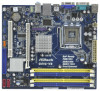
Top: RJ-45 Super IO HD_AUDIO1 1 LAN PHY EUP_LAN 1 1 EUP_AUDIO1 AUDIO CODEC 8Mb BIOS FSB1 1 CMOS Battery LPT1 Intel G41 Chipset PCIE1 RoHS CHA_FAN1 CLRCMOS1 USB6_7 1 USB4_5 1 PCI1 SPEAKER1 1 PANEL 1 PLED PWRBTN 1 HDLED RESET 17 16 15 14 13 12 DX10 G41C-VS Intel ICH7 IDE1 11 SATAII_2 - ASRock G41C-VS | User Manual - Page 11
Purple) * To enable Multi-Streaming function, you need to connect a front panel audio cable to the front panel audio header. Please refer to below steps for the software setting of Multi-Streaming. For Windows® XP: After restarting your computer, you will find "Mixer" tool on your system. Please - ASRock G41C-VS | User Manual - Page 12
G41C-VS is a Micro ATX form factor (8.8" x 7.8", 22.4 x 19.8 cm) motherboard. Before you install the motherboard, study the configuration of your chassis to ensure that the motherboard fits into it. Make sure to unplug the power cord before installing or removing the motherboard. Failure - ASRock G41C-VS | User Manual - Page 13
For the installation of Intel 775-LAND CPU, please follow the steps below. 775-Pin Socket Overview Before you insert the 775-LAND CPU into the socket, please check if the CPU surface is unclean or if there is any bent pin on the socket. Do not force to insert the CPU into the socket if - ASRock G41C-VS | User Manual - Page 14
CPU is within the socket and properly mated to the orient keys. Step 3. Remove PnP Cap (Pick and Place Cap): Use your left hand index finger and thumb to support PnP cap. 2. This cap must be placed if returning the motherboard for after service. Step 4. Close the socket: Step 4-1. Rotate the load - ASRock G41C-VS | User Manual - Page 15
Heatsink This motherboard is equipped with 775-Pin socket that supports Intel 775-LAND CPU. Please adopt the type of heatsink and cooling fan compliant with Intel 775-LAND CPU to dissipate heat. Before you installed the heatsink, you need to spray thermal interface material between the CPU and the - ASRock G41C-VS | User Manual - Page 16
motherboard provides two 240-pin DDR2 (Double Data Rate 2) DIMM slots and two 240-pin DDR3 (Double Data Rate 3) DIMM slots, and supports Dual Channel Memory Technology. For dual channel configuration, you always need to install identical (the same brand, speed, size and chip-type) DDR2/DDR3 DIMM - ASRock G41C-VS | User Manual - Page 17
matches the break on the slot. notch break notch break The DIMM only fits in one correct orientation. It will cause permanent damage to the motherboard and the DIMM if you force the DIMM into the slot at incorrect orientation. Step 3. Firmly insert the DIMM into the slot until the retaining - ASRock G41C-VS | User Manual - Page 18
) There are 1 PCI slot and 1 PCI Express slot on this motherboard. PCI slot: PCI slot is used to install expansion card that has the 32-bit PCI interface. PCIE slot: PCIE1 (PCIE x16 slot) is used for PCI Express card with x16 lane width graphics card. If you install the add-on PCI Express VGA - ASRock G41C-VS | User Manual - Page 19
EUP Audio Jumper (EUP_LAN1, 3-pin jumper, see p.10 No. 22) (EUP_AUDIO1, 3-pin jumper, see p.10 No. 21) EUP_LAN1 EUP_AUDIO1 Default (Enable EuP) Note: EUP_LAN and EUP_AUDIO jumper design decreases the power consumption of this motherboard to meet EuP standard. With an ASRock EuP ready motherboard - ASRock G41C-VS | User Manual - Page 20
10 No. 20) FSB1 Default If you adopt FSB1333-CPU and DDR3 1333 memory module on this motherboard, you need to adjust the jumper. Please short pin2, pin3 for FSB1 jumper. Otherwise, the CPU and memory module may not work properly on this motherboard. Please refer to below jumper setting. FSB1 - ASRock G41C-VS | User Manual - Page 21
cable that allows convenient connection and control of audio devices. 1. High Definition Audio supports Jack Sensing, but the panel wire on the chassis must support HDA to function correctly. Please follow the instruction in our manual and chassis manual to install your system. 2. If you use AC - ASRock G41C-VS | User Manual - Page 22
For Windows® XP / XP 64-bit OS: Click "Audio I/O", select "Connector Settings" , choose "Disable front panel jack detection", and save the change by clicking "OK". For Windows® 7 / 7 64-bit / VistaTM / VistaTM 64-bit OS: Click the right-top "Folder" icon , choose "Disable front panel jack - ASRock G41C-VS | User Manual - Page 23
ATX Power Connector 24 (24-pin ATXPWR1) (see p.10 No. 4) 12 Please connect an ATX power 13 supply to this connector. 1 Though this motherboard provides 24-pin ATX power connector, it can still work if you adopt a traditional 20-pin ATX power supply. To use the 20-pin ATX - ASRock G41C-VS | User Manual - Page 24
guide. Some default setting of SATAII hard disks may not be at SATAII mode, which operate with the best performance. In order to enable SATAII function, please follow the below instruction website for details: http://www.hitachigst.com/hdd/support/download.htm The above examples are just for your - ASRock G41C-VS | User Manual - Page 25
, the drivers compatible to your system can be auto-detected and listed on the support CD driver page. Please follow the order from up to bottom side to install those required drivers. Therefore, the drivers you install can work properly. 2.12 Untied Overclocking Technology This motherboard supports - ASRock G41C-VS | User Manual - Page 26
BIOS SETUP UTILITY to configure your system. The SPI Memory on the motherboard stores the BIOS SETUP UTILITY. You may run the BIOS Because the BIOS software is constantly being updated, the following BIOS setup screens set up overclocking features Advanced To set up the advanced BIOS features H/W - ASRock G41C-VS | User Manual - Page 27
10/26/2009] Use [Enter], [TAB] or [SHIFT-TAB] to select a field. BIOS Version : G41C-VS P1.00 Processor Type : Intel (R) Core (TM) 2 Duo CPU E6850 @ 3.00GHz (64bit) Processor Speed : 3148MHz Microcode Update : 6FB/B6 Cache Size : 1024KB Total Memory DDRII1 DDRII2 DDR3_1 DDR3_2 : 2048MB - ASRock G41C-VS | User Manual - Page 28
667MHz DDR3_1333] for DDR3 or [266MHz DDR2_533], [333MHz DDR2_667] or [400MHz DDR2_800] for DDR2. The configuration options depend on the CPU and memory module you adopt on this motherboard. Please refer to page 8 for the CPU FSB frequency and its corresponding memory support frequency. DRAM Command - ASRock G41C-VS | User Manual - Page 29
Configuration BIOS SETUP UTILITY OC Tweaker DRAM Timing Control DRAM tCL 6 DRAM tRCD 6 DRAM tRP 6 DRAM tRAS 15 DRAM tRFC 44 DRAM tWR 6 DRAM tWTR 4 DRAM tRRD 3 DRAM tRTP 4 [Auto] [Auto] [Auto] [Auto] [Auto] [Auto] [Auto] [Auto] [Auto] DRAM tCL Value DDR2 Min = 3 Max = 7 DDR3 Min - ASRock G41C-VS | User Manual - Page 30
hidden if the current CPU does not support Intel (R) SpeedStep(tm) tech.. Please note that enabling this function may reduce CPU voltage and lead to system stability or compatibility issue with some power supplies. Please set this item to [Disable] if above issue occurs. Overclock Mode Use this to - ASRock G41C-VS | User Manual - Page 31
GLTREF Voltage Use this to select GLTREF Voltage. Configuration options: [Auto], [0.67 x Vtt], [0.65 x Vtt], [0.63 x Vtt] and [0.615 x Vtt]. The default value of this feature is [Auto]. Would you like to save current setting user defaults? In this option, you are allowed to load and save three user - ASRock G41C-VS | User Manual - Page 32
wrong values in below sections may cause system to malfunction. CPU Configuration Chipset Configuration ACPI Configuration Storage Configuration PCIPnP Configuration SuperIO Configuration USB Configuration BIOS Update Utility ASRock Instant Flash Select Screen Select Item Enter Go to Sub Screen - ASRock G41C-VS | User Manual - Page 33
value, please disable the option " Intel (R) SpeedStep(tm) tech." in advance. Enhance Halt State All processors support the Halt State (C1). The C1 state is supported through the native processor instructions HLT and MWAIT and requires no hardware support from the chipset. In the C1 power state, the - ASRock G41C-VS | User Manual - Page 34
] if using Microsoft® Windows® XP, or Linux kernel version 2.4.18 or higher. This option will be hidden if the installed CPU does not support Hyper-Threading technology. Intel (R) SpeedStep(tm) tech. Intel (R) SpeedStep(tm) tech. is Intel's new power saving technology. Processor can switch between - ASRock G41C-VS | User Manual - Page 35
3.4.2 Chipset Configuration BIOS SETUP UTILITY Advanced Chipset Settings DRAM RCOMP and tRD Configuration DRAM DLL SKEW Configuration Fixed Mode Operation [Enabled] Intelligent Energy Saver Primary Graphics Adapter Shared Memory PAVP Mode DVMT Mode Select DVMT/FIXED Memory [Disabled] [PCI] [ - ASRock G41C-VS | User Manual - Page 36
DRAM CH0 G3 (Control2) This controls the number of DRAM CH0 G3 (Control2). Min: 1. Max: 15. The default value is [Auto]. DRAM CH0 G4 (Clocks1) This controls the number of DRAM CH0 G4 (Clocks1). Min: 1. Max: 15. The default value is [Auto]. DRAM CH0 G5 (Clocks2) This controls the number of DRAM CH0 - ASRock G41C-VS | User Manual - Page 37
DRAM DLL SKEW Configuration BIOS SETUP UTILITY Advanced DRAM DLL SKEW Settings DRAM CH0 CLKSET0 SKEW Info:0-0-0-0-0-0 DRAM CH0 CLKSET0 SKEW [Auto] DRAM CH0 CLKSET1 SKEW Info:0-0-0-0-0-0 DRAM CH0 CLKSET1 - ASRock G41C-VS | User Manual - Page 38
DRAM CH1 CMD SKEW This controls the number of DRAM CH1 CMD SKEW. The default value is [Auto]. DRAM CH1 CTRL0 SKEW This controls the number of DRAM CH1 CTRL0 SKEW. The default value is [Auto]. DRAM CH1 CTRL1 SKEW This controls the number of DRAM CH1 CTRL1 SKEW. The default value is [Auto]. DRAM CH1 - ASRock G41C-VS | User Manual - Page 39
PAVP mode. Configuration options: [Disabled] and [Lite]. The default value is [Disabled]. PAVP is the new graphics feature in Intel® 4 Series Express chipset family to support increased content protection and robustness requirements for premium content playback (Bluray disc). [Lite] mode is the - ASRock G41C-VS | User Manual - Page 40
to enable or disable the "OnBoard Lan" feature. 3.4.3 ACPI Configuration BIOS SETUP UTILITY Advanced ACPI Configuration Suspend To disable the Suspend-toRAM feature. Select [Auto] will enable this feature if the OS supports it. If you set this item to [Disabled], the function "Repost Video on STR - ASRock G41C-VS | User Manual - Page 41
plan to use this motherboard to submit Windows® VistaTM certification. 3.4.4 Storage Configuration BIOS SETUP UTILITY Advanced Storage Compatible] when you install legacy OS (Windows® NT). If native OS (Windows® 7 / VistaTM / XP) is installed, please select [Enhanced]. When [Compatible - ASRock G41C-VS | User Manual - Page 42
detect the hard disk drive. After selecting the hard disk information into BIOS, use a disk utility, such as FDISK, to partition and format select the LBA/Large mode for a hard disk > 512 MB under DOS and Windows; for Netware and UNIX user, select [Disabled] to disable compatible IDE devices. 42 - ASRock G41C-VS | User Manual - Page 43
to maximize the IDE hard disk data transfer rate. 3.4.5 PCIPnP Configuration BIOS SETUP UTILITY Advanced Advanced PCI / PnP Settings PCI Latency Timer PCI IDE to keep the default value unless the installed PCI expansion cards' specifications require other settings. PCI IDE BusMaster Use this item - ASRock G41C-VS | User Manual - Page 44
SETUP UTILITY Advanced Configure Super IO Chipset Serial Port Address Parallel Port Address Parallel Port Mode EPP Version ECP Mode DMA Channel Parallel Port IRQ [3F8 / IRQ4] [378] [ECP + EPP] [1.9] [DMA3] [IRQ7] Allow BIOS to Enable or Disable Floppy Controller. +F1 F9 F10 ESC Select Screen - ASRock G41C-VS | User Manual - Page 45
. [Disabled] - USB devices are not allowed to use under legacy OS and BIOS setup when [Disabled] is selected. If you have USB compatibility issue, it is recommended to select [Disabled] to enter OS. [BIOS Setup Only] - USB devices are allowed to use only under BIOS setup and Windows® / Linux OS. 45 - ASRock G41C-VS | User Manual - Page 46
to monitor the status of the hardware on your system, including the parameters of the CPU temperature, motherboard temperature, CPU fan speed, chassis fan speed, and the critical voltage. BIOS SETUP UTILITY Main OC Tweaker Advanced H/W Monitor Boot Security Exit Hardware Health Event Monitoring - ASRock G41C-VS | User Manual - Page 47
for you to configure the boot settings and the boot priority. BIOS SETUP UTILITY Main OC Tweaker Advanced H/W Monitor Boot Security Exit From Onboard LAN Bootup Num-Lock [Enabled] [Enabled] [Auto] [Disabled] [On] Disabled: Displays normal POST messages. Enabled: Displays OEM Logo instead of - ASRock G41C-VS | User Manual - Page 48
option "Full Screen Logo". Configuration options: [Auto], [EuP], [Scenery] and [ASRock]. The default value is [Auto]. Currently, the option [Auto] is set to Aircraft. Boot From Onboard LAN Use this item to enable or disable the Boot From Onboard LAN feature. Boot Up Num-Lock If this item is set to - ASRock G41C-VS | User Manual - Page 49
Load BIOS default values for all the setup questions. F9 key can be used for this operation. Load Performance Setup Default (IDE/SATA) This performance setup default may not be compatible with all system configurations. If system boot failure occurs after loading, please resume optimal default - ASRock G41C-VS | User Manual - Page 50
/ XP / XP 64-bit. Because motherboard settings and hardware options vary, use the setup procedures in this chapter for general reference only. Refer to your OS documentation for more information. 4.2 Support CD Information The Support CD that came with the motherboard contains necessary drivers and
-
 1
1 -
 2
2 -
 3
3 -
 4
4 -
 5
5 -
 6
6 -
 7
7 -
8
-
9
-
10
-
11
-
12
-
13
-
14
-
15
-
16
-
17
-
18
-
19
-
20
-
21
-
22
-
23
-
24
-
25
-
26
-
27
-
28
-
29
-
30
-
31
-
32
-
33
-
34
-
35
-
36
-
37
-
38
-
39
-
40
-
41
-
42
-
43
-
44
-
45
-
46
-
47
-
48
-
49
-
50
 |
 |

1
G41C-VS
User Manual
Version 1.0
Published October 2009
Copyright©2009 ASRock INC. All rights reserved.