ASRock G41M-GS User Manual
ASRock G41M-GS Manual
 |
View all ASRock G41M-GS manuals
Add to My Manuals
Save this manual to your list of manuals |
ASRock G41M-GS manual content summary:
- ASRock G41M-GS | User Manual - Page 1
G41M-GS User Manual Version 1.0 Published July 2009 Copyright©2009 ASRock INC. All rights reserved. 1 - ASRock G41M-GS | User Manual - Page 2
purchaser for backup purpose, without written consent of ASRock Inc. Products and corporate names appearing in this manual may or may not be registered trademarks or copyrights USA ONLY The Lithium battery adopted on this motherboard contains Perchlorate, a toxic substance controlled in Perchlorate - ASRock G41M-GS | User Manual - Page 3
2.10 Serial ATA (SATA) / Serial ATAII (SATAII) Hard Disks Installation 25 2.11 Driver Installation Guide 25 2.12 Untied Overclocking Technology 25 3 BIOS SETUP UTILITY 26 3.1 Introduction 26 3.1.1 BIOS Menu Bar 26 3.1.2 Navigation Keys 27 3.2 Main Screen 27 3.3 Smart Screen 28 3.4 Advanced - ASRock G41M-GS | User Manual - Page 4
4 Software Support 50 4.1 Install Operating System 50 4.2 Support CD Information 50 4.2.1 Running Support CD 50 4.2.2 Drivers Menu 50 4.2.3 Utilities Menu 50 4.2.4 Contact Information 50 4 - ASRock G41M-GS | User Manual - Page 5
and CPU support lists on ASRock website as well. ASRock website http://www.asrock.com If you require technical support related to this motherboard, please visit our website for specific information about the model you are using. www.asrock.com/support/index.asp 1.1 Package Contents ASRock G41M-GS - ASRock G41M-GS | User Manual - Page 6
Specifications Platform CPU Chipset Memory Expansion Slot Graphics Audio LAN Rear Panel I/O - Micro ATX Form Factor: 9.6-in x 7.6-in, 24.4 cm x 19.3 cm - LGA 775 for Intel® CoreTM 2 Extreme / CoreTM 2 Quad / CoreTM 2 Duo / Pentium® Dual Core / Celeron® Dual Core / Celeron®, supporting Penryn Quad - ASRock G41M-GS | User Manual - Page 7
2.0 ports) (see CAUTION 9) BIOS Feature - 8Mb AMI BIOS - AMI Legal BIOS - Supports "Plug and Play" - ACPI 1.1 Compliance Wake Up Events - AMBIOS 2.3.1 Support - Supports Smart BIOS Support CD - Drivers, Utilities, AntiVirus Software (Trial Version) Unique Feature - ASRock OC Tuner (see - ASRock G41M-GS | User Manual - Page 8
Overclocking Technology" on page 25 for details. 4. This motherboard supports Dual Channel Memory Technology. Before you implement Dual Channel Memory Technology, make sure to read the installation guide and Windows® VistaTM 64- bit with 64-bit CPU, there is no such limitation. 7. The maximum - ASRock G41M-GS | User Manual - Page 9
website for the operation procedures of Intelligent Energy Saver. ASRock website: http://www.asrock.com 12. ASRock Instant Flash is a BIOS flash utility embedded in Flash ROM. This convenient BIOS update tool allows you to update system BIOS without entering operating systems first like MS-DOS or - ASRock G41M-GS | User Manual - Page 10
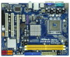
18 17 16 15 14 13 12 G41M-GS SATAII_2 SATAII_4 24.4cm (9.6 in) 6 7 8 9 10 11 1 PS2_USB_PWR1 Jumper 16 USB 2.0 Header (USB4_5, Blue) 2 775-Pin CPU Socket 17 System Panel Header (PANEL1, Orange) 3 North Bridge Controller 18 BIOS SPI Chip 4 CPU Fan Connector (CPU_FAN1) 19 Chassis Fan - ASRock G41M-GS | User Manual - Page 11
ACT/LINK SPEED LED LED Off No Link Off 10Mbps connection Blinking Data Activity Orange 100Mbps connection On Link Green 1Gbps connection LAN Port * To enable Multi-Streaming function, you need to connect a front panel audio cable to the front panel audio header. Please refer - ASRock G41M-GS | User Manual - Page 12
G41M-GS is a Micro ATX form factor (9.6" x 7.6", 24.4 x 19.3 cm) motherboard. Before you install the motherboard, study the configuration of your chassis to ensure that the motherboard fits into it. Make sure to unplug the power cord before installing or removing the motherboard. Failure - ASRock G41M-GS | User Manual - Page 13
the installation of Intel 775-LAND CPU, please follow the steps below. 775-Pin Socket Overview Before you insert the 775-LAND CPU into the socket, please check if the CPU surface is unclean or if there is any bent pin on the socket. Do not force to insert the CPU into the socket if above situation - ASRock G41M-GS | User Manual - Page 14
to use the cap tab to handle and avoid kicking off the PnP cap. 2. This cap must be placed if returning the motherboard for after service. Step 4. Close the socket: Step 4-1. Rotate the load plate onto the IHS. Step 4-2. While pressing down lightly on load plate, engage the load lever. Step - ASRock G41M-GS | User Manual - Page 15
Heatsink This motherboard is equipped with 775-Pin socket that supports Intel 775-LAND CPU. Please adopt the type of heatsink and cooling fan compliant with Intel 775-LAND CPU to dissipate heat. Before you installed the heatsink, you need to spray thermal interface material between the CPU and the - ASRock G41M-GS | User Manual - Page 16
2.5 Installation of Memory Modules (DIMM) G41M-GS motherboard provides two 240-pin DDR2 (Double Data Rate 2) DIMM slots, and supports Dual Channel Memory Technology. For dual channel configuration, you always need to install two identical (the same brand, speed, size and chip-type) memory modules - ASRock G41M-GS | User Manual - Page 17
and 2 PCI Express slots on this motherboard. PCI slots: PCI slots are used Express cards with x1 lane width cards, such as Gigabit LAN card, SATA2 card, etc. PCIE2 (PCIE x16 slot) VGA card to PCIE2 (PCIE x16 slot) and adjust the BIOS options "Primary Graphics Adapter" to [Onboard] and "Share Memory - ASRock G41M-GS | User Manual - Page 18
decreases the power consumption of this motherboard to meet EuP standard. With an ASRock EuP ready motherboard and a power supply that the noticed that when EUP_LAN jumper is set to enabled, the Wake-On-LAN function under S3 (Suspend to RAM), S4 (Suspend to Disk), and S5 (Soft Off) will be - ASRock G41M-GS | User Manual - Page 19
to FSB1333 (by BIOS setting) you may face the problem, that DRAM frequency will be overclocked very high. Please use jumper to force NB to be strapped at higher frequency, so the DRAM can work at lower frequency. If you want to overclock the CPU you adopt to FSB1066 on this motherboard, you need to - ASRock G41M-GS | User Manual - Page 20
, see p.10 No. 7) PIN1 IDE1 connect the blue end connect the black end to the motherboard to the IDE devices 80-conductor ATA 66/100 cable Note: Please refer to the instruction of your IDE device vendor for the details. SATAII_1 SATAII_3 SATAII_2 SATAII_4 Serial ATAII Connectors (SATAII_1 - ASRock G41M-GS | User Manual - Page 21
USB 2.0 headers on this motherboard. Each USB 2.0 header can support two USB 2.0 ports. supports Jack Sensing, but the panel wire on the chassis must support HDA to function correctly. Please follow the instruction in our manual and chassis manual audio panel. E. Enter BIOS Setup Utility. Enter - ASRock G41M-GS | User Manual - Page 22
to the ground pin. Though this motherboard provides 4-Pin CPU fan (Quiet Fan) support, the 3-Pin CPU fan still can work successfully even without the fan speed control function. If you plan to connect the 3-Pin CPU fan to the CPU fan connector on this motherboard, please connect it to Pin 1-3. Pin - ASRock G41M-GS | User Manual - Page 23
ATX Power Connector (24-pin ATXPWR1) (see p.10 No. 6) 12 24 Please connect an ATX power supply to this connector. 1 13 Though this motherboard provides 24-pin ATX power connector, 12 24 it can still work if you adopt a traditional 20-pin ATX power supply. To use the 20- - ASRock G41M-GS | User Manual - Page 24
guide. Some default setting of SATAII hard disks may not be at SATAII mode, which operate with the best performance. In order to enable SATAII function, please follow the below instruction website for details: http://www.hitachigst.com/hdd/support/download.htm The above examples are just for your - ASRock G41M-GS | User Manual - Page 25
be auto-detected and listed on the support CD driver page. Please follow the order from up to bottom side to install those required drivers. Therefore, the drivers you install can work properly. 2.12 Untied Overclocking Technology This motherboard supports Untied Overclocking Technology, which means - ASRock G41M-GS | User Manual - Page 26
the BIOS SETUP UTILITY to configure your system. The BIOS FWH chip on the motherboard stores the BIOS SETUP UTILITY. You may run the BIOS SETUP off and then back on. Because the BIOS software is constantly being updated, the following BIOS setup screens and descriptions are for reference purpose - ASRock G41M-GS | User Manual - Page 27
Exit System Overview System Time System Date [14:00:09] [Fri 06/12/2009] BIOS Version : G41M-GS P1.00 Processor Type : Intel(R) CPU 3.20GHz (64bit) Processor Speed : 3200MHz Microcode Update : F64/4 Cache Size : 4096KB Total Memory DDRII1 DDRII2 : 1024MB with 128MB shared memory and - ASRock G41M-GS | User Manual - Page 28
H/W Monitor Boot Security Exit Smart Settings Save Changes and Exit Load BIOS Defaults Load Performance Setup Default (IDE/SATA) Load Power Saving Setup Default BIOS Update Utility ASRock Instant Flash EZ Overclocking Load Optimized CPU OC Setting [Press Enter] Exit system setup after saving the - ASRock G41M-GS | User Manual - Page 29
appears when you adopt E5000 series CPU. You can use this option to load the optiomized CPU overclocking setting. Configuration options: [2.64 GHz], [2.88 GHz], [3.00 GHz], [3.12 GHz] and [3.27 GHz]. Please note that overclocing may cause damage to your CPU and motherboard. It should be done at your - ASRock G41M-GS | User Manual - Page 30
Overclock Mode Use this to select Overclock Mode. The default value is [Auto]. Cnfiguration options: [Auto], [Manual] and [Optimized]. CPU Frequency (MHz) Use this option to adjust CPU you changing the ratio value of this motherboard. If the CPU you adopt supports EIST (Intel (R) SpeedStep(tm) - ASRock G41M-GS | User Manual - Page 31
to [Enabled] if using Microsoft® Windows® XP, or Linux kernel version 2.4.18 or higher. This option will be hidden if the installed CPU does not support Hyper-Threading technology. On-Demand Clock Modulation This provides the On-Demand Clock Modulation duty cycle. It indicates the clock on to clock - ASRock G41M-GS | User Manual - Page 32
3.4.2 Chipset Configuration BIOS SETUP UTILITY Advanced Chipset Configuration Memory Remap Feature [Disabled] depend on the CPU and memory module you adopt on this motherboard. Please refer to page 8 for the CPU FSB frequency and its corresponding memory support frequency. Flexibility Option - ASRock G41M-GS | User Manual - Page 33
DRAM tWR This controls the number of DRAM clocks for TWR. Min: 3. Max: 15. The default value is [Auto]. DRAM tWTR This controls the number of DRAM clocks for TWTR. Min: 2. Max: 15. The default value is [Auto]. DRAM tRRD This controls the number of DRAM clocks for TRRD. Min: 2. Max: 15. The default - ASRock G41M-GS | User Manual - Page 34
DRAM RCOMP STRENGTH Configuration BIOS SETUP UTILITY Advanced DRAM RCOMP STRENGTH Settings DRAM CH0 RCOMP STRENGTH Info : 0-10-7-7-7-7 DRAM CH0 G0 (Data) [Auto] DRAM CH0 G1 (Command) [Auto] DRAM CH0 - ASRock G41M-GS | User Manual - Page 35
DRAM CH1 G3 (Control2) This controls the number of DRAM CH1 G3 (Control2). Min: 1. Max: 15. The default value is [Auto]. DRAM CH1 G4 (Clocks1) This controls the number of DRAM CH1 G4 (Clocks1). Min: 1. Max: 15. The default value is [Auto]. DRAM CH1 G5 (Clocks2) This controls the number of DRAM CH1 - ASRock G41M-GS | User Manual - Page 36
DRAM DLL SKEW Settings BIOS SETUP UTILITY Advanced DRAM DLL SKEW Settings DRAM CH0 CLKSET0 SKEW Info:0-0-0-0-0-0 DRAM CH0 CLKSET0 SKEW [Auto] DRAM CH0 CLKSET1 SKEW Info:0-0-0-0-0-0 DRAM CH0 CLKSET1 - ASRock G41M-GS | User Manual - Page 37
DRAM CH1 CMD SKEW This controls the number of DRAM CH1 CMD SKEW. The default value is [Auto]. DRAM CH1 CTRL0 SKEW This controls the number of DRAM CH1 CTRL0 SKEW. The default value is [Auto]. DRAM CH1 CTRL1 SKEW This controls the number of DRAM CH1 CTRL1 SKEW. The default value is [Auto]. DRAM CH1 - ASRock G41M-GS | User Manual - Page 38
chipset family to support increased content protection and motherboard through efficient memory utilization. In DVMT mode, the graphics driver Lan This allows you to enable or disable the "OnBoard Lan" feature. CPU Voltage Use this to select CPU Voltage. Configuration options: [Auto] and [Manual - ASRock G41M-GS | User Manual - Page 39
. The default value is [Disabled]. Configuration options: [Enabled] and [Disabled]. If you want to enable this function, please set this item to [Enabled]. Besides the BIOS option, you can also choose our Intelligent Energy Saver utility to enable this function. 39 - ASRock G41M-GS | User Manual - Page 40
3.4.3 ACPI Configuration BIOS SETUP UTILITY Advanced ACPI Configuration Suspend To RAM Repost Video on STR Resume Check Ready or disable the Suspend-toRAM feature. Select [Auto] will enable this feature if the OS supports it. If you set this item to [Disabled], the function "Repost Video on STR - ASRock G41M-GS | User Manual - Page 41
to use this motherboard to submit Windows® VistaTM certification. 3.4.4 IDE Configuration BIOS SETUP UTILITY Advanced then all SATAII will not work, only IDE will work. Because Intel® ICH7 south bridge only supports four IDE devices under legacy OS (Windows NT), you have to choose [SATA 1, SATA 2, - ASRock G41M-GS | User Manual - Page 42
the "Primary IDE Master" as the example in the following instruction. BIOS SETUP UTILITY Advanced Primary IDE Master Device Vendor Size LBA Mode Block Data Transfer :Hard Disk :ST340014A :40.0 GB :Supported :16Sectors :4 :MultiWord DMA-2 :Ultra DMA-5 :Supported [Auto] [Auto] [Auto] [Auto] [Auto] - ASRock G41M-GS | User Manual - Page 43
], [Enabled]. 32-Bit Data Transfer Use this item to enable 32-bit access to maximize the IDE hard disk data transfer rate. 3.4.5 PCIPnP Configuration BIOS SETUP UTILITY Advanced Advanced PCI / PnP Settings PCI Latency Timer PCI IDE BusMaster [32] [Enabled] Value in units of PCI clocks for PCI - ASRock G41M-GS | User Manual - Page 44
Port Address Parallel Port Mode EPP Version ECP Mode DMA Channel Parallel Port IRQ [Enabled] [3F8 / IRQ4] [378] [ECP + EPP] [1.9] [DMA3] [IRQ7] Allow BIOS to Enable or Disable Floppy Controller. +F1 F9 F10 ESC Select Screen Select Item Change Option General Help Load Defaults Save and Exit Exit - ASRock G41M-GS | User Manual - Page 45
to set the IRQ for the parallel port. Configuration options: [IRQ5] and [IRQ7]. 3.4.8 USB Configuration BIOS SETUP UTILITY Advanced USB Configuration USB Controller USB 2.0 Support Legacy USB Support [Enabled] [Enabled] [Enabled] To enable or disable the onboard USB controllers. +F1 F9 F10 ESC - ASRock G41M-GS | User Manual - Page 46
you to monitor the status of the hardware on your system, including the parameters of the CPU temperature, motherboard temperature, CPU fan speed, chassis fan speed, and the critical voltage. BIOS SETUP UTILITY Main Smart Advanced H/W Monitor Boot Security Exit Hardware Health Event Monitoring - ASRock G41M-GS | User Manual - Page 47
the boot settings and the boot priority. BIOS SETUP UTILITY Main Smart Advanced H/W Monitor Boot Screen Logo AddOn ROM Display Boot Logo Boot From Onboard LAN Bootup Num-Lock [Enabled] [Enabled] [Auto] series], [Scenery] and [ASRock]. The default value is [Auto]. Currently, the option [Auto] is - ASRock G41M-GS | User Manual - Page 48
this item to enable or disable the Boot From Onboard LAN feature. Boot Up Num-Lock If this item is set to /user password for the system. For the user password, you may also clear it. BIOS SETUP UTILITY Main Smart Advanced H/W Monitor Boot Security Exit Security Settings Supervisor Password : Not - ASRock G41M-GS | User Manual - Page 49
and exit setup?" Select [OK] to save the changes and exit the BIOS SETUP UTILITY. Discard Changes and Exit When you select this option, it message, "Discard changes and exit setup?" Select [OK] to exit the BIOS SETUP UTILITY without saving any changes. Discard Changes When you select this option - ASRock G41M-GS | User Manual - Page 50
install the necessary drivers to activate the devices. 4.2.3 Utilities Menu The Utilities Menu shows the applications software that the motherboard supports. Click on a specific item then follow the installation wizard to install it. 4.2.4 Contact Information If you need to contact ASRock or want to
-
 1
1 -
 2
2 -
 3
3 -
 4
4 -
 5
5 -
 6
6 -
 7
7 -
8
-
9
-
10
-
11
-
12
-
13
-
14
-
15
-
16
-
17
-
18
-
19
-
20
-
21
-
22
-
23
-
24
-
25
-
26
-
27
-
28
-
29
-
30
-
31
-
32
-
33
-
34
-
35
-
36
-
37
-
38
-
39
-
40
-
41
-
42
-
43
-
44
-
45
-
46
-
47
-
48
-
49
-
50
 |
 |

1
G41M-GS
User Manual
Version 1.0
Published July 2009
Copyright©2009 ASRock INC. All rights reserved.