ASRock G41M-GS Quick Installation Guide
ASRock G41M-GS Manual
 |
View all ASRock G41M-GS manuals
Add to My Manuals
Save this manual to your list of manuals |
ASRock G41M-GS manual content summary:
- ASRock G41M-GS | Quick Installation Guide - Page 1
for backup purpose, without written consent of ASRock Inc. Products and corporate names appearing in this guide may or may not be registered trademarks or ASRock Website: http://www.asrock.com Published July 2009 Copyright©2009 ASRock INC. All rights reserved. 1 ASRock G41M-GS Motherboard English - ASRock G41M-GS | Quick Installation Guide - Page 2
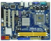
Motherboard Layout English 1 PS2_USB_PWR1 Jumper 16 USB 2.0 Header (USB4_5, Blue) 2 775-Pin CPU Socket 17 System Panel Header (PANEL1, Orange) 3 North Bridge Controller 18 BIOS SPI Chip 4 CPU ) 29 ATX 12V Connector (ATX12V1) 15 USB 2.0 Header (USB6_7, Blue) 2 ASRock G41M-GS Motherboard - ASRock G41M-GS | Quick Installation Guide - Page 3
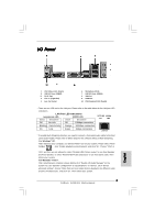
Off 10Mbps connection Blinking Data Activity Orange 100Mbps connection On Link Green 1Gbps connection LAN Port * To enable Multi-Streaming function, you need to connect a front panel streams simultaneously", and click "ok". Then reboot your system. 3 ASRock G41M-GS Motherboard English - ASRock G41M-GS | Quick Installation Guide - Page 4
and CPU support lists on ASRock website as well. ASRock website http://www.asrock.com If you require technical support related to this motherboard, please visit our website for specific information about the model you are using. www.asrock.com/support/index.asp 1.1 Package Contents ASRock G41M-GS - ASRock G41M-GS | Quick Installation Guide - Page 5
Wake-On-LAN I/O Panel - 1 x PS/2 Mouse Port - 1 x PS/2 Keyboard Port - 1 x Serial Port: COM1 - 1 x VGA Port - 4 x Ready-to-Use USB 2.0 Ports - 1 x RJ-45 LAN Port with LED (ACT/LINK LED and SPEED LED) - HD Audio Jack: Line in / Front Speaker / Microphone English 5 ASRock G41M-GS Motherboard - ASRock G41M-GS | Quick Installation Guide - Page 6
2.0 ports) (see CAUTION 9) BIOS Feature - 8Mb AMI BIOS - AMI Legal BIOS - Supports "Plug and Play" - ACPI 1.1 Compliance Wake Up Events - AMBIOS 2.3.1 Support - Supports Smart BIOS Support CD - Drivers, Utilities, AntiVirus Software (Trial Version) Unique Feature - ASRock OC Tuner (see - ASRock G41M-GS | Quick Installation Guide - Page 7
overclocking, including adjusting the setting in the BIOS, applying Untied Overclocking Technology, or using the third-party overclocking tools. Overclocking VistaTM 64- bit with 64-bit CPU, there is no such limitation. Guide" on page 24 of "User Manual" in the support CD ASRock G41M-GS Motherboard - ASRock G41M-GS | Quick Installation Guide - Page 8
Saver. ASRock website: http://www.asrock.com 12. ASRock Instant Flash is a BIOS flash utility embedded in Flash ROM. This convenient BIOS update tool allows you to update system BIOS without you checking with the power supply manufacturer for more details. 8 ASRock G41M-GS Motherboard English - ASRock G41M-GS | Quick Installation Guide - Page 9
Before you insert the 775-LAND CPU into the socket, please check if the CPU surface is unclean or if there is any bent pin on the socket. Do not force to insert the CPU into the socket if above situation is found. Otherwise, the CPU will be seriously damaged. 9 ASRock G41M-GS Motherboard English - ASRock G41M-GS | Quick Installation Guide - Page 10
100 degrees. Step 2. Insert the 775-LAND CPU: Step 2-1. Hold the CPU by the edges where are marked with support the load plate edge, engage PnP cap with right hand thumb and peel the cap from the socket while pressing on center of PnP cap to assist in removal. 10 ASRock G41M-GS Motherboard - ASRock G41M-GS | Quick Installation Guide - Page 11
, the heatsink cannot be secured on the motherboard. Step 5. Step 6. Connect fan header with the CPU fan connector on the motherboard. Secure excess cable with tie-wrap to ensure cable does not interfere with fan operation or contact other components. 11 ASRock G41M-GS Motherboard English - ASRock G41M-GS | Quick Installation Guide - Page 12
2.3 Installation of Memory Modules (DIMM) G41M-GS motherboard provides two 240-pin DDR2 (Double Data Rate 2) DIMM slots, and supports Dual Channel Memory Technology. For dual channel configuration, you always need to install two identical (the same brand, speed, size and chiptype) memory modules in - ASRock G41M-GS | Quick Installation Guide - Page 13
for PCI Express cards with x1 lane width cards, such as Gigabit LAN card, SATA2 card, etc. PCIE2 (PCIE x16 slot) is used for on PCI Express VGA card to PCIE2 (PCIE x16 slot) and adjust the BIOS options "Primary Graphics Adapter" to [Onboard] and "Share Memory" to [ ASRock G41M-GS Motherboard English - ASRock G41M-GS | Quick Installation Guide - Page 14
want to disable this power saving function, you may short pin2 and pin3. Please be noticed that when EUP_LAN jumper is set to enabled, the Wake-On-LAN function under S3 (Suspend to RAM), S4 (Suspend to Disk), and S5 (Soft Off) will be disabled. (Disable EuP) 14 ASRock G41M-GS Motherboard - ASRock G41M-GS | Quick Installation Guide - Page 15
to overclock the CPU you adopt to FSB1333 on this motherboard, you need to adjust the jumpers. Please short pin3, pin4 for FSB2 jumper and pin4, pin5 for FSB3 jumper. Otherwise, the CPU may not work properly on this motherboard. Please refer to below jumper settings. 15 ASRock G41M-GS Motherboard - ASRock G41M-GS | Quick Installation Guide - Page 16
to the power connector on each drive. Then connect the white end of SATA power cable to the power connector of the power supply. 16 ASRock G41M-GS Motherboard English - ASRock G41M-GS | Quick Installation Guide - Page 17
supports Jack Sensing, but the panel wire on the chassis must support HDA to function correctly. Please follow the instruction in our manual and chassis manual them for AC'97 audio panel. E. Enter BIOS Setup Utility. Enter Advanced Settings, and then select ASRock G41M-GS Motherboard English - ASRock G41M-GS | Quick Installation Guide - Page 18
) support, the 3-Pin CPU fan still can work successfully even without the fan speed control function. If you plan to connect the 3-Pin CPU fan to the CPU fan connector on this motherboard, please connect it to Pin 1-3. Pin 1-3 Connected 3-Pin Fan Installation English 18 ASRock G41M-GS Motherboard - ASRock G41M-GS | Quick Installation Guide - Page 19
(see p.2 No. 6) 12 24 Please connect an ATX power supply to this connector. 1 13 Though this motherboard provides 24-pin ATX power connector, 12 24 it can still work if you adopt a traditional 20-pin ATX do so will cause the failure to power up. English tion 19 ASRock G41M-GS Motherboard - ASRock G41M-GS | Quick Installation Guide - Page 20
during overclocking, but PCI / PCIE buses are in the fixed mode so that FSB can operate under a more stable overclocking environment. Please refer to the warning on page 7 for the possible overclocking risk before you apply Untied Overclocking Technology. 20 ASRock G41M-GS Motherboard English - ASRock G41M-GS | Quick Installation Guide - Page 21
detailed information about BIOS Setup, please refer to the User Manual (PDF file) contained in the Support CD. 4. Software Support CD information This motherboard supports various Microsoft® EXE" from the BIN folder in the Support CD to display the menus. 21 ASRock G41M-GS Motherboard English - ASRock G41M-GS | Quick Installation Guide - Page 22
Modell benötigen, besuchen Sie bitte unsere Webseite: www.asrock.com/support/index.asp 1.1 Kartoninhalt ASRock G41M-GS Motherboard (Micro ATX-Formfaktor: 24.4 cm x 19.3 cm; 9.6 Zoll x 7.6 Zoll) ASRock G41M-GS Schnellinstallationsanleitung ASRock G41M-GS Support-CD Ein 80-adriges Ultra-ATA 66/100 IDE - ASRock G41M-GS | Quick Installation Guide - Page 23
ützt Wake-On-LAN I/O Panel - 1 x PS/2-Mausanschluss - 1 x PS/2-Tastaturanschluss - 1 x Serieller port: COM 1 - 1 x VGA Port - 4 x Standard-USB 2.0-Anschlüsse - 1 x RJ-45 LAN Port mit LED (ACT/LINK LED und SPEED LED) - Audioanschlüsse: Line In / Line Out / Mikrofon 23 ASRock G41M-GS Motherboard - ASRock G41M-GS | Quick Installation Guide - Page 24
- 1 x FDD-Anschlüsse - 1 x Druckerport-Anschlussleiste - CPU/Gehäuse-Lüfteranschluss - 24-pin ATX-Netz-Header - 4-pin anschluss BIOS Support-CD - Treiber, Dienstprogramme, Antivirussoftware (Probeversion) Einzigartige - ASRock : http://www.asrock.com Deutsch 24 ASRock G41M-GS Motherboard - ASRock G41M-GS | Quick Installation Guide - Page 25
wird. Unter Windows® XP 64-bit und Windows® Vista™ 64-bit mit 64-Bit-CPU besteht diese Einschränkung nicht. 7. Die Maximalspeichergröße ist von den Chipshändler definiert und umgetauscht. Bitte überprüfen Sie Intel® website für die neuliche Information. Deutsch 25 ASRock G41M-GS Motherboard - ASRock G41M-GS | Quick Installation Guide - Page 26
" auf der Support-CD, um Ihre CPU-Lüfter am Motherboard richtig funktioniert, und stecken Sie bitte den Stromkabelstecker aus und dann wieder ein. Um die Wärmeableitung zu verbessern, bitte nicht vergessen, etwas Wärmeleitpaste zwischen CPU und Kühlkörper zu sprühen. 26 ASRock G41M-GS Motherboard - ASRock G41M-GS | Quick Installation Guide - Page 27
sie ausgeschaltet sind. Um dem EuP-Standard zu entsprechen, sind ein EuP-fähiges Motherboard und eine EuP-fähige Stromversorgung erforderlich. Gemäß einer Empfehlung von Intel muss eine EuP überbrücken Sie 2-pin von CLRCMOS1 mithilfe des Jumpers für 5 Sekunden. 27 ASRock G41M-GS Motherboard Deutsch - ASRock G41M-GS | Quick Installation Guide - Page 28
. Andernfalls arbeiten CPU und Speichermodule eventuell nicht richtig mit Ihrem Motherboard. DRAM CPU JumperEinstellungen DDR2 533 FSB533 DDR2 1066 FSB1066 FSB1333 FSB1: 2-3 FSB2: 1-2 FSB3: 2-3 FSB1: 1-2 FSB2: 1-2 FSB3: 2-3 FSB1: 1-2 FSB2: 4-5 FSB3: 1-2 Deutsch 28 ASRock G41M-GS Motherboard - ASRock G41M-GS | Quick Installation Guide - Page 29
ändern. Bitte überbrücken Sie die Pins 3 und 4 der Steckbrücke FSB2 und die Pins 4 und 5 der Steckbrücke FSB3. Andernfalls arbeitet die CPU eventuell nicht richtig mit Ihrem Motherboard. Bitte schauen Sie sich die nachstehenden Steckbrückeneinstellungen an. Deutsch 29 ASRock G41M-GS Motherboard - ASRock G41M-GS | Quick Installation Guide - Page 30
Header und Anschlüsse. Wenn Sie Jumperkappen auf Header und Anschlüsse setzen, wird das Motherboard unreparierbar beschädigt! Anschluss für das Floppy-Laufwerk (33-Pin FLOPPY1) (siehe S.2 - SATAIIFestplatte oder dem SATAII-Anschluss am Mainboard verbinden. Deutsch 30 ASRock G41M-GS Motherboard - ASRock G41M-GS | Quick Installation Guide - Page 31
blichen USB 2.0-Ports an den I/O-Anschlüssen befinden sich zwei USB 2.0-Anschlussleisten am Motherboard. Pro USB 2.0Anschlussleiste werden zwei USB 2.0-Ports unterstützt. Druckerport-Anschlussleiste (25 nachstehend beschrieben an der Front-Audioanschlussleiste: 31 ASRock G41M-GS Motherboard Deutsch - ASRock G41M-GS | Quick Installation Guide - Page 32
sse müssen nicht an die AC'97-Audioleiste angeschlossen werden. E. Rufen Sie das BIOS-Setup-Dienstprogramm auf. Wechseln Sie zu Erweiterte Einstellungen und wählen Sie Chipset-Konfiguration. S.2 - No. 14) Schließen Sie den Gehäuselautsprecher an diesen Header an. 32 ASRock G41M-GS Motherboard - ASRock G41M-GS | Quick Installation Guide - Page 33
angeschlossen werden; auch ohne Geschwindigkeitsregulierung. Wenn Sie einen dreipoligen CPU-Lüfter an den CPU-Lüferanschluss dieses Motherboards anschließen möchten, verbinden Sie ihn bitte mit den . Andernfalls reicht der Strom nicht aus, das System zu starten. 33 ASRock G41M-GS Motherboard - ASRock G41M-GS | Quick Installation Guide - Page 34
Verzeichnis der Support-CD, um die Menüs aufzurufen. Das Setup-Programm soll es Ihnen so leicht wie möglich machen. Es ist menügesteuert, d.h. Sie können in den verschiedenen Untermenüs Ihre Auswahl treffen und die Programme werden dann automatisch installiert. 34 ASRock G41M-GS Motherboard Deutsch - ASRock G41M-GS | Quick Installation Guide - Page 35
9.6 pouces x 7.6 pouces, 24.4 cm x 19.3 cm) Guide d'installation rapide ASRock G41M-GS CD de soutien ASRock G41M-GS Un câble ruban IDE Ultra ATA 66/100 80 conducteurs (en option) Un câbles d'alimentation de série ATA (SATA) HDD (en option) Un I/O Panel Shield 35 ASRock G41M-GS Motherboard Français - ASRock G41M-GS | Quick Installation Guide - Page 36
- Support du Wake-On-LAN I/O Panel - 1 x port souris PS/2 - 1 x port clavier PS/2 - 1 x port série: COM 1 - 1 x port VGA - 4 x ports USB 2.0 par défaut - 1 x port LAN RJ-45 avec LED (ACT/LED CLIGNOTANTE et LED VITESSE) - Jack audio: entrée ligne / sortie ligne / microphone ASRock G41M-GS Motherboard - ASRock G41M-GS | Quick Installation Guide - Page 37
CPU/Châssis - br. 24 connecteur d'alimentation ATX - br. 4 connecteur d'alimentation 12V ATX - Connecteur audio panneau avant - 2 x en-tête USB 2.0 (accepte 4 ports USB 2.0) (voir ATTENTION 9) - 8Mb BIOS AMI - BIOS AMI - Support requise) (voir ATTENTION 15) Français 37 ASRock G41M-GS Motherboard - ASRock G41M-GS | Quick Installation Guide - Page 38
® VistaTM 64 bits avec CPU 64 bits, il n'y a pas ce genre de limitation. 7. La dimension maximum du memoire partage est definie par le vendeur de jeu de puces et est sujet de changer. Veuillez verifier la Intel® website pour les informations recentes SVP. 38 ASRock G41M-GS Motherboard Français - ASRock G41M-GS | Quick Installation Guide - Page 39
Guide « Installation du disque dur SATAII » à la page 24 du « Manuel de l'utilisateur » qui se trouve sur le CD de support d'un usage facile ASRock overclocking outil qui vous permet de surveiller votre système en CPU le dissipateur lors de l'installation du PC. 39 ASRock G41M-GS Motherboard Français - ASRock G41M-GS | Quick Installation Guide - Page 40
. Puis placez un cavalier sur les pins CLRCMOS1 pendant 5 secondes. N'oubliez pas de retirer le cavalier avant après avoir restauré le CMOS. Français 40 ASRock G41M-GS Motherboard - ASRock G41M-GS | Quick Installation Guide - Page 41
é, la fonction de réveil Wake-OnLAN sous S3 (Suspendre vers RAM), S4 (Suspendre vers Disque), CPU Réglages des cavaliers DDR2 533 FSB533 DDR2 1066 FSB1066 FSB1333 FSB1: 2-3 FSB2: 1-2 FSB3: 2-3 FSB1: 1-2 FSB2: 1-2 FSB3: 2-3 FSB1: 1-2 FSB2: 4-5 FSB3: 1-2 Français 41 ASRock G41M-GS Motherboard - ASRock G41M-GS | Quick Installation Guide - Page 42
devez régler les cavaliers. Veuillez court-circuiter pin3, pin4 pour le cavalier FSB2 et pin4, pin5 pour le cavalier FSB3. Sinon, le CPU pourrait ne pas fonctionner correctement sur cette carte mère. Veuillez vous référer aux réglages de cavaliers ci-dessous. 42 ASRock G41M-GS Motherboard Français - ASRock G41M-GS | Quick Installation Guide - Page 43
connecteur noir vers le disque dur Câble ATA 66/100 80 conducteurs Note: Veuillez vous reporter aux instructions du fabricant de votre IDE périphérique pour les détails. Connecteurs Série ATAII (SATAII_1: voir SATA / SATAIIou au connecteur SATAII sur la carte mère. 43 ASRock G41M-GS Motherboard - ASRock G41M-GS | Quick Installation Guide - Page 44
correctement. Veuillez suivre les instructions dans notre manuel et le manuel de châssis afin installer votre système. 2. Si vous utilisez le panneau audio AC'97, installez-le sur l'adaptateur audio du panneau avant conformément à la procédure ci-dessous: 44 ASRock G41M-GS Motherboard Français - ASRock G41M-GS | Quick Installation Guide - Page 45
pas besoin de les connecter pour le panneau audio AC'97. E. Entrer dans l'utilitaire de configuration du BIOS. Saisir les Paramètres avancés puis sélectionner Configuration du jeu de puces. Définir l'option panneau de le haut-parleur de châssis sur cet en-tête. 45 ASRock G41M-GS Motherboard - ASRock G41M-GS | Quick Installation Guide - Page 46
brancher le fil ien que cette carte mère offre un support de (Ventilateur silencieux) ventilateur de CPU à 4 broches , le ventilateur de CPU à 3 broches peut bien fonctionner même sans la fonction unité d'alimentation électrique ATX 12V sur ce connecteur. Français 46 ASRock G41M-GS Motherboard - ASRock G41M-GS | Quick Installation Guide - Page 47
détaillées sur le BIOS, veuillez consulter le Guide de l'utilisateur (fichier PDF) dans le CD technique. 3. Informations sur le CD de support Cette carte mère supporte divers systèmes d'exploitation Microsoft double-cliquez dessus pour afficher les menus. Français 47 ASRock G41M-GS Motherboard - ASRock G41M-GS | Quick Installation Guide - Page 48
di CPU supportate. ASRock website http://www.asrock.com Se si necessita dell'assistenza tecnica per questa scheda madre, visitare il nostro sito per informazioni specifiche sul modello che si sta usando. www.asrock.com/support/index.asp 1.1 Contenuto della confezione Scheda madre ASRock G41M-GS - ASRock G41M-GS | Quick Installation Guide - Page 49
Supporta Wake-On-LAN I/O Panel - 1 x porta PS/2 per mouse - 1 x porta PS/2 per tastiera - 1 x Porta COM - 1 x Porta VGA - 4 x porte USB 2.0 già integrate - 1 x porte LAN RJ-45 con LED (LED azione/collegamento e LED velocità) - Audio Jack: Line In / Line Out / Microfono 49 ASRock G41M-GS Motherboard - ASRock G41M-GS | Quick Installation Guide - Page 50
wake up events - Supporta SMBIOS 2.3.1 - Smart BIOS supportato CD di - Driver, utilità, software antivirus (Versione dimostrativa) supporto Caratteris- - Sintonizzatore ASRock di raffreddamento - Ventola CPU silenziosa - Voltaggio: +12V asrock.com Italiano 50 ASRock G41M-GS Motherboard - ASRock G41M-GS | Quick Installation Guide - Page 51
la configurazione del disco rigido SATAII" a pagina 24 del "Manuale utente" nel CD in dotazione in modo da poter predisporre il disco rigido SATAII per la modalità SATAII. È anche possibile connettere il disco rigido SATA direttamente al connettore SATAII. 51 ASRock G41M-GS Motherboard Italiano - ASRock G41M-GS | Quick Installation Guide - Page 52
% con un consumo di corrente di 100 mA. Per la scelta di un'alimentatore predisposto EuP consigliamo di verificare ulteriori dettagli con il produttore. 52 ASRock G41M-GS Motherboard Italiano - ASRock G41M-GS | Quick Installation Guide - Page 53
questa funzione di risparmio energetico, è possibile accorciare il pin2 e il pin3. Quando il jumper EUP_LAN è impostato su abilitato, le funzioni Wake-On-LAN sotto S3 (sospendi su RAM), S4 (sospendi su disco), e S5 (Soft Off) verranno disabilitate. (Disabilita EuP) 53 ASRock G41M-GS Motherboard - ASRock G41M-GS | Quick Installation Guide - Page 54
si monta una CPU FSB800 o una FSB1066 e si prova ad eseguire l'overcloccaggio a FSB1333 (con le impostazioni del BIOS) si possono avere CPU potrebbe non funzionare correttamente su questa scheda madre. Fare riferimento alle impostazioni dei ponticelli riportate sotto. 54 ASRock G41M-GS Motherboard - ASRock G41M-GS | Quick Installation Guide - Page 55
Serial ATA (SATA) (Opzionale) Entrambe le estremità del cavo dati SATA possono collegarsi all'hard disk SATA / SATAII o al connettore SATAII sulla scheda madre. 55 ASRock G41M-GS Motherboard - ASRock G41M-GS | Quick Installation Guide - Page 56
che questa operi in modo corretto. Attenersi alle istruzioni del nostro manuale e del manuale del telaio per installare il sistema. 2. Se si utilizza un pannello audio AC'97, installarlo nell'intestazione audio del pannello anteriore, come indicato di seguito: 56 ASRock G41M-GS Motherboard Italiano - ASRock G41M-GS | Quick Installation Guide - Page 57
collegarli per il pannello audio AC'97. E. Entrare nel programma di impostazione BIOS. Entrare su Impostazioni avanzate, quindi selezionare Configurazione chipset. Impostare l'opzione Comando pannello Nr. 14) Collegare le casse del telaio a questo collettore. 57 ASRock G41M-GS Motherboard - ASRock G41M-GS | Quick Installation Guide - Page 58
pin terra. Sebbene la presente scheda madre disponga di un supporto per ventola CPU a 4 piedini (ventola silenziosa), la ventola CPU a 3 piedini è in grado di funzionare anche senza la funzione di controllo sufficiente. In caso contrario l'unità non si avvia. Italiano 58 ASRock G41M-GS Motherboard - ASRock G41M-GS | Quick Installation Guide - Page 59
sullo chassis del sistema. Per informazioni più dettagliate circa il Setup del BIOS, fare riferimento al Manuale dell'Utente (PDF file) contenuto nel cd di supporto. 3. Software di supporto e informazioni supporto e cliccare due volte per visualizzare i menù. Italiano 59 ASRock G41M-GS Motherboard - ASRock G41M-GS | Quick Installation Guide - Page 60
forma Micro ATX: 24,4 cm x 19,3 cm, 9,6" x 7,6") Guía de instalación rápida de ASRock G41M-GS CD de soporte de ASRock G41M-GS Una cinta de datos IDE de conducción 80 Ultra ATA 66/100 (Opcional) Una cables de datos Serial ATA (SATA) (Opcional) Una protección I/O 60 ASRock G41M-GS Motherboard Español - ASRock G41M-GS | Quick Installation Guide - Page 61
-LAN I/O Panel - 1 x puerto de ratón PS/2 - 1 x puerto de teclado PS/2 - 1 x puerto serial: COM1 - 1 x Puerto VGA - 4 x puertos USB 2.0 predeterminados - 1 x Puerto LAN RJ-45 con LED (LED de ACCIÓN/ENLACE y LED de VELOCIDAD) - Audio Jack: Line In / Line Out / Micrófono 61 ASRock G41M-GS Motherboard - ASRock G41M-GS | Quick Installation Guide - Page 62
del ventilador del CPU/chasis - 24-pin BIOS - AMI legal BIOS - Soporta "Plug and Play" - ACPI 1.1 compliance wake up events - Soporta SMBIOS 2.3.1 - Compatible con Smart BIOS - Controladores, Utilerías, Software de Anti Virus (Versión de prueba) - Sintonizador de ASRock ASRock G41M-GS Motherboard - ASRock G41M-GS | Quick Installation Guide - Page 63
reloj, incluido el ajuste del BIOS, aplicando la tecnología de Por favor consulte página 31 del Manual del Usuario en el soporte CD sobre "Tecnología de Forzado de Reloj (Overclocking) no relacionado" en la página CPU de 64-bit, no existe dicha limitación. 63 ASRock G41M-GS Motherboard Español - ASRock G41M-GS | Quick Installation Guide - Page 64
24 del "Manual de usuario" que CPU está sobre-elevada, el sistema va a apagarse automaticamente. Antes de reanudar el sistema, compruebe si el ventilador de la CPU de la placa base funciona apropiadamente y desconecte el cable de alimentación, a continuación, vuelva a 64 ASRock G41M-GS Motherboard - ASRock G41M-GS | Quick Installation Guide - Page 65
cortocircuito pin 2, (vea p.2, N. 1) pin 3 para habilitar +5VSB (standby) para PS/2 o USB wake up events. Atención: Para elegir +5VSB, se necesita corriente mas que 2 Amp proveida por la fuente los pins de CLRCMOS1 por más que 5 segundos usando un jumper cap. 65 ASRock G41M-GS Motherboard - ASRock G41M-GS | Quick Installation Guide - Page 66
, puede que la CPU y el módulo de memoria no funcionen adecuadamente en esta placa base. DRAM CPU Configuraciones de Puente DDR2 533 FSB533 FSB1: 2-3 FSB2: 1-2 FSB3: 2-3 DDR2 1066 FSB1066 FSB1: 1-2 FSB2: 1-2 FSB3: 2-3 FSB1333 FSB1: 1-2 FSB2: 4-5 FSB3: 1-2 Español 66 ASRock G41M-GS Motherboard - ASRock G41M-GS | Quick Installation Guide - Page 67
ón: CUando monta una CPU FSB800 ó FSB1066, e intenta sobreacelerar a FSB1333 (por la configuración del BIOS) puede encontrarse con así, puede que la CPU no funcione adecuadamente en esta placa base. Por favor, consulte las siguientes configuraciones de puente. Español 67 ASRock G41M-GS Motherboard - ASRock G41M-GS | Quick Installation Guide - Page 68
de serie ATA (SATA) (Opcional) Ambos extremos del cable pueden conectarse al disco duro SATA / SATAII o la conexión de la placa base. Español 68 ASRock G41M-GS Motherboard - ASRock G41M-GS | Quick Installation Guide - Page 69
manual y en el manual de chasis para instalar su sistema. 2. Si utiliza el panel de sonido AC'97, instálelo en la cabecera de sonido del panel frontal de la siguiente manera: A. Conecte Mic_IN (MIC) a MIC2_L. B. Conecte Audio_R (RIN) a OUT2_R y Audio_L (LIN) en OUT2_L. 69 ASRock G41M-GS Motherboard - ASRock G41M-GS | Quick Installation Guide - Page 70
necesitará conectarlos al panel de sonido AC'97. E. Entre en la Utilidad de configuración del BIOS Entre en Configuración avanzada y, a continuación, seleccione Configuración del conjunto de chips. En el panel y haga coincidir el cable negro con el conector de tierra. 70 ASRock G41M-GS Motherboard - ASRock G41M-GS | Quick Installation Guide - Page 71
pin CPU_FAN1) (vea p.2, N. 3) 4 3 2 1 Conecte el cable del ventilador de la CPU a este conector y haga coincidir el cable negro con el conector de tierra. Aunque esta placa modo que proporcione suficiente electricidad. De lo contrario no se podrá encender. Español 71 ASRock G41M-GS Motherboard - ASRock G41M-GS | Quick Installation Guide - Page 72
la Utilidad de configuración de la BIOS, consulte el Manual del usuario (archivo PDF), que se encuentra en el CD de soporte. 3.Información de Software Support CD Esta placa-base soporta diversos -pulse en el archivo "ASSETUP.EXE" para iniciar la instalación. 72 ASRock G41M-GS Motherboard Español - ASRock G41M-GS | Quick Installation Guide - Page 73
-GS (Formato Micro ATX: 9,6 pol. x 7,6 pol., 24,4 cm x 19,3 cm) Guia de instalação rápida da ASRock G41M-GS CD de suporte da placa ASRock G41M-GS Um cabo-fita IDE Ultra ATA 66/100 de 80 condutores (Opcional) Um cabo de dados ATA Serial (SATA) (Opcional) Uma proteção I/O 85 ASRock G41M-GS Motherboard - ASRock G41M-GS | Quick Installation Guide - Page 74
Wake-On-LAN I/O Panel - 1 x porta para mouse PS/2 - 1 x porta para teclado PS/2 - 1 x porta COM1 - 1 x porta VGA - 4 x portas USB 2.0 padrão - 1 x porta LAN RJ-45 com LED (LED ACT/LIG e LED VELOCIDADE) - Áudio Jack: saída / entrada de linha / microfone + porta de jogos 86 ASRock G41M-GS Motherboard - ASRock G41M-GS | Quick Installation Guide - Page 75
Ventoinha silenciosa para a CPU - Monitoramento de voltagem : +12 V, +5 V, +3.3 V, Vcore - Microsoft® Windows® 2000 / XP / XP de 64 bits / VistaTM / VistaTM de 64 bits - FCC, CE - "EuP Ready" (é necessária alimentação eléctrica "EuP Ready") (veja o AVISO 15) 87 ASRock G41M-GS Motherboard Português - ASRock G41M-GS | Quick Installation Guide - Page 76
CPU de 64 bits do Windows® XP de 64 bits e do Windows® VistaTM de 64 bits, esta limitação não existe. 7. O máximo tamanho de memória compartilhada é definido por vendedor de chipset e é sujeito a mudar. Verifique o Intel® website para a última informação. 88 ASRock G41M-GS Motherboard Portugu - ASRock G41M-GS | Quick Installation Guide - Page 77
Manual overclocking da ASRock fácil de CPU na placa-mãe, para verificar se está funcionando corretamente antes de religar o sistema. Para melhorar a dissipação de calor, lembre-se de aplicar o material de interface térmica entre o processador e o dissipador de calor. 89 ASRock G41M-GS Motherboard - ASRock G41M-GS | Quick Installation Guide - Page 78
Pin2, Pin3 curtos para (veja a folha 2, No. 1) habilitar +5VSB (stand by) para PS/2 ou eventos de wake up na USB. Nota: Para escolher +5VSB, é preciso uma corrente de stand by de 2 A ou mais. mais de 5 segundos para limpar o CMOS usando um jumper. Português 90 ASRock G41M-GS Motherboard - ASRock G41M-GS | Quick Installation Guide - Page 79
és das definições da BIOS) pode encontrar o problema de a frequência DRAM ser sujeito a um overclock demasiado elevado. Utilize por favor os jumpers para forçar a NB a ser puxada a uma frequência maior para que a DRAM possa funcionar a uma frequência menor. 91 ASRock G41M-GS Motherboard Português - ASRock G41M-GS | Quick Installation Guide - Page 80
favor as configurações dos jumpers abaixo. Se quiser fazer o overclock ao CPU que adoptar para FSB 1333 nesta placa-mãe, tem de ajustar os contrário, o CPU pode não funcionar devidamente nesta placa-mãe. Consulte por favor as configurações dos jumpers abaixo. 92 ASRock G41M-GS Motherboard Português - ASRock G41M-GS | Quick Installation Guide - Page 81
do cabo de Serial dados SATA pode ser conectado ao disco rígido SATA / SATAII quanto o conector SATAII na placa mãe. SATAII_1 SATAII_3 SATAII_2 SATAII_4 Português 93 ASRock G41M-GS Motherboard - ASRock G41M-GS | Quick Installation Guide - Page 82
e no manual do chassis para instalar o sistema. 2. Se utilizar o painel de áudio AC'97, instale-o no cabeçalho de áudio do painel frontal, como a figura abaixo mostra: A. Ligue o Mic_IN (MIC) ao MIC2_L. B. Ligue o Audio_R (RIN) ao OUT2_R e o Audio_L (LIN) ao OUT2_L. 94 ASRock G41M-GS Motherboard - ASRock G41M-GS | Quick Installation Guide - Page 83
necessita de os ligar para o painel de áudio AC'97. E. Entre no utilitário de configuração do BIOS. Vá até à opção Definições avançadas e escolha Configuração do chipset. Defina a opção Controlo neste conector, coincidindo o fio preto com o pino de aterramento. 95 ASRock G41M-GS Motherboard - ASRock G41M-GS | Quick Installation Guide - Page 84
de controlo de velocidade da ventoinha. Se pretender ligar uma ventoinha de 3 pinos para CPU ao conector de ventoinha do CPU nesta placa-mãe, por favor, ligue-a aos pinos 1-3. Pinos 1-3 ligados Instalação de Do contrário, haverá falhas de funcionamento. Português 96 ASRock G41M-GS Motherboard - ASRock G41M-GS | Quick Installation Guide - Page 85
. Para as informações detalhadas sobre o Utilitário de Configuração do BIOS, consulte o Manual do Usuário (arquivo PDF) no CD de suporte. 3. Informações do CD de Suporte Esta automaticamente, explore o CD e execute o "ASSETUP.EXE" localizado na pasta BIN. Português 97 ASRock G41M-GS Motherboard - ASRock G41M-GS | Quick Installation Guide - Page 86
98 ASRock G41M-GS Motherboard - ASRock G41M-GS | Quick Installation Guide - Page 87
® ® / ® ® ® ® ® ® 99 ASRock G41M-GS Motherboard - ASRock G41M-GS | Quick Installation Guide - Page 88
® 100 ASRock G41M-GS Motherboard - ASRock G41M-GS | Quick Installation Guide - Page 89
" " ® ® ® ® ® " " " " ASRock G41M-GS Motherboard 101 - ASRock G41M-GS | Quick Installation Guide - Page 90
® ® 102 ASRock G41M-GS Motherboard - ASRock G41M-GS | Quick Installation Guide - Page 91
"" "" "" "" ASRock G41M-GS Motherboard 103 - ASRock G41M-GS | Quick Installation Guide - Page 92
104 ASRock G41M-GS Motherboard - ASRock G41M-GS | Quick Installation Guide - Page 93
SATAII_1 SATAII_3 SATAII_2 SATAII_4 ASRock G41M-GS Motherboard 105 - ASRock G41M-GS | Quick Installation Guide - Page 94
106 ASRock G41M-GS Motherboard - ASRock G41M-GS | Quick Installation Guide - Page 95
® ® ® ® " " " " " " ® " " " "" " 4 3 2 1 ASRock G41M-GS Motherboard 107 - ASRock G41M-GS | Quick Installation Guide - Page 96
12 24 1 13 12 24 1 13 108 ASRock G41M-GS Motherboard - ASRock G41M-GS | Quick Installation Guide - Page 97
" " 12 24 1 13 " " \\ ASRock G41M-GS Motherboard 109 - ASRock G41M-GS | Quick Installation Guide - Page 98
110 ASRock G41M-GS Motherboard - ASRock G41M-GS | Quick Installation Guide - Page 99
® ® ® ® ® ® ® ® ASRock G41M-GS Motherboard 111 - ASRock G41M-GS | Quick Installation Guide - Page 100
112 ® ® ASRock G41M-GS Motherboard - ASRock G41M-GS | Quick Installation Guide - Page 101
" " ® ® ® ® ® ASRock G41M-GS Motherboard 113 - ASRock G41M-GS | Quick Installation Guide - Page 102
® ® TM TM ® ® 114 ASRock G41M-GS Motherboard - ASRock G41M-GS | Quick Installation Guide - Page 103
ASRock G41M-GS Motherboard 115 - ASRock G41M-GS | Quick Installation Guide - Page 104
116 ASRock G41M-GS Motherboard - ASRock G41M-GS | Quick Installation Guide - Page 105
SATAII_1 SATAII_3 SATAII_2 SATAII_4 ASRock G41M-GS Motherboard 117 - ASRock G41M-GS | Quick Installation Guide - Page 106
118 ASRock G41M-GS Motherboard - ASRock G41M-GS | Quick Installation Guide - Page 107
® ® ® ® ® 4 3 2 1 ASRock G41M-GS Motherboard 119 - ASRock G41M-GS | Quick Installation Guide - Page 108
12 24 1 13 12 24 1 13 120 ASRock G41M-GS Motherboard - ASRock G41M-GS | Quick Installation Guide - Page 109
12 24 ® ® TM 1 13 TM ASRock G41M-GS Motherboard 121 - ASRock G41M-GS | Quick Installation Guide - Page 110
122 ASRock G41M-GS Motherboard - ASRock G41M-GS | Quick Installation Guide - Page 111
® ® ® ® ® ® ® ® ASRock G41M-GS Motherboard 123 - ASRock G41M-GS | Quick Installation Guide - Page 112
® ® 124 ASRock G41M-GS Motherboard - ASRock G41M-GS | Quick Installation Guide - Page 113
® ® ® ® ® ® ® ASRock G41M-GS Motherboard 125 - ASRock G41M-GS | Quick Installation Guide - Page 114
® ® 126 ASRock G41M-GS Motherboard - ASRock G41M-GS | Quick Installation Guide - Page 115
ASRock G41M-GS Motherboard 127 - ASRock G41M-GS | Quick Installation Guide - Page 116
128 SATAII_1 SATAII_3 SATAII_2 SATAII_4 ASRock G41M-GS Motherboard - ASRock G41M-GS | Quick Installation Guide - Page 117
ASRock G41M-GS Motherboard 129 - ASRock G41M-GS | Quick Installation Guide - Page 118
® ® ® ® 130 4 3 2 1 ASRock G41M-GS Motherboard - ASRock G41M-GS | Quick Installation Guide - Page 119
12 24 1 13 12 24 1 13 ASRock G41M-GS Motherboard 131 - ASRock G41M-GS | Quick Installation Guide - Page 120
® ® 132 ASRock G41M-GS Motherboard - ASRock G41M-GS | Quick Installation Guide - Page 121
X O O O X O O O O: X: O O O O ASRock G41M-GS Motherboard 133 - ASRock G41M-GS | Quick Installation Guide - Page 122
134 ASRock G41M-GS Motherboard - ASRock G41M-GS | Quick Installation Guide - Page 123
® ® ® ® ® ® ® ® ASRock G41M-GS Motherboard 135 - ASRock G41M-GS | Quick Installation Guide - Page 124
136 ® ® ASRock G41M-GS Motherboard - ASRock G41M-GS | Quick Installation Guide - Page 125
® ® ® ® ® ® ® ASRock G41M-GS Motherboard 137 - ASRock G41M-GS | Quick Installation Guide - Page 126
® ® 138 ASRock G41M-GS Motherboard - ASRock G41M-GS | Quick Installation Guide - Page 127
ASRock G41M-GS Motherboard 139 - ASRock G41M-GS | Quick Installation Guide - Page 128
140 ASRock G41M-GS Motherboard - ASRock G41M-GS | Quick Installation Guide - Page 129
SATAII_1 SATAII_3 SATAII_2 SATAII_4 ASRock G41M-GS Motherboard 141 - ASRock G41M-GS | Quick Installation Guide - Page 130
142 ® ASRock G41M-GS Motherboard - ASRock G41M-GS | Quick Installation Guide - Page 131
® ® ® ® 4 3 2 1 ASRock G41M-GS Motherboard 143 - ASRock G41M-GS | Quick Installation Guide - Page 132
12 24 1 13 12 24 1 13 ® ® ® 144 ASRock G41M-GS Motherboard
-
 1
1 -
 2
2 -
 3
3 -
 4
4 -
 5
5 -
 6
6 -
 7
7 -
8
-
9
-
10
-
11
-
12
-
13
-
14
-
15
-
16
-
17
-
18
-
19
-
20
-
21
-
22
-
23
-
24
-
25
-
26
-
27
-
28
-
29
-
30
-
31
-
32
-
33
-
34
-
35
-
36
-
37
-
38
-
39
-
40
-
41
-
42
-
43
-
44
-
45
-
46
-
47
-
48
-
49
-
50
-
51
-
52
-
53
-
54
-
55
-
56
-
57
-
58
-
59
-
60
-
61
-
62
-
63
-
64
-
65
-
66
-
67
-
68
-
69
-
70
-
71
-
72
-
73
-
74
-
75
-
76
-
77
-
78
-
79
-
80
-
81
-
82
-
83
-
84
-
85
-
86
-
87
-
88
-
89
-
90
-
91
-
92
-
93
-
94
-
95
-
96
-
97
-
98
-
99
-
100
-
101
-
102
-
103
-
104
-
105
-
106
-
107
-
108
-
109
-
110
-
111
-
112
-
113
-
114
-
115
-
116
-
117
-
118
-
119
-
120
-
121
-
122
-
123
-
124
-
125
-
126
-
127
-
128
-
129
-
130
-
131
-
132
 |
 |

1
ASRock
G41M-GS
Motherboard
English
English
English
English
English
Copyright Notice:
Copyright Notice:
Copyright Notice:
Copyright Notice:
Copyright Notice:
No part of this installation guide may be reproduced, transcribed, transmitted, or trans-
lated in any language, in any form or by any means, except duplication of documen-
tation by the purchaser for backup purpose, without written consent of ASRock Inc.
Products and corporate names appearing in this guide may or may not be registered
trademarks or copyrights of their respective companies, and are used only for identifica-
tion or explanation and to the owners’ benefit, without intent to infringe.
Disclaimer:
Disclaimer:
Disclaimer:
Disclaimer:
Disclaimer:
Specifications and information contained in this guide are furnished for informational
use only and subject to change without notice, and should not be constructed as a
commitment by ASRock. ASRock assumes no responsibility for any errors or omissions
that may appear in this guide.
With respect to the contents of this guide, ASRock does not provide warranty of any kind,
either expressed or implied, including but not limited to the implied warranties or
conditions of merchantability or fitness for a particular purpose. In no event shall
ASRock, its directors, officers, employees, or agents be liable for any indirect, special,
incidental, or consequential damages (including damages for loss of profits, loss of
business, loss of data, interruption of business and the like), even if ASRock has been
advised of the possibility of such damages arising from any defect or error in the guide
or product.
This device complies with Part 15 of the FCC Rules. Operation is subject to the
following two conditions:
(1)
this device may not cause harmful interference, and
(2)
this device must accept any interference received, including interference that
may cause undesired operation.
Published July 2009
Copyright
©
2009 ASRock INC. All rights reserved.
CALIFORNIA, USA ONLY
The Lithium battery adopted on this motherboard contains Perchlorate, a toxic
substance controlled in Perchlorate Best Management Practices (BMP) regulations
passed by the California Legislature. When you discard the Lithium battery in
California, USA, please follow the related regulations in advance.
“Perchlorate Material-special handling may apply, see
www
.dtsc.ca.gov/hazardouswa
ste/perchlorate”
ASRock Website: http://www.asrock.com