ASRock G41M-LE User Manual
ASRock G41M-LE Manual
 |
View all ASRock G41M-LE manuals
Add to My Manuals
Save this manual to your list of manuals |
ASRock G41M-LE manual content summary:
- ASRock G41M-LE | User Manual - Page 1
G41M-LE User Manual Version 1.0 Published October 2008 Copyright©2008 ASRock INC. All rights reserved. 1 - ASRock G41M-LE | User Manual - Page 2
purchaser for backup purpose, without written consent of ASRock Inc. Products and corporate names appearing in this manual may or may not be registered trademarks or copyrights USA ONLY The Lithium battery adopted on this motherboard contains Perchlorate, a toxic substance controlled in Perchlorate - ASRock G41M-LE | User Manual - Page 3
(BD) / HD-DVD Playback Support ...1.4 Passed Full HD 1080p Blu-ray (BD) / HD-DVD Films in Our Lab Test ...1.5 Motherboard Layout ...1.6 I/O Panel ...5 6 11 Driver Installation Guide ...26 2.12 Untied Overclocking Technology ...26 3 BIOS S ETUP UTILITY ...27 SETUP 3.1 Introduction ...3.1.1 BIOS Menu - ASRock G41M-LE | User Manual - Page 4
Screen ...3.6 Boot Screen ...3.5.1 Boot Settings Configuration ...3.7 Security Screen ...3.8 Exit Screen ...4.1 Install Operating System ...4.2 Support CD Information ...4.2.1 Running Support CD ...4.2.2 Drivers Menu ...4.2.3 Utilities Menu ...4.2.4 Contact Information ... 43 44 44 45 46 47 47 47 47 - ASRock G41M-LE | User Manual - Page 5
information about the model you are using. www.asrock.com/support/index.asp 1.1 P ack age Contents ackage ASRock G41M-LE Motherboard (Micro ATX Form Factor: 9.6-in x 8.6-in, 24.4 cm x 21.8 cm) ASRock G41M-LE Quick Installation Guide ASRock G41M-LE Support CD One 80-conductor Ultra ATA 66/100 IDE - ASRock G41M-LE | User Manual - Page 6
1.2 Specifications - Micro ATX Form Factor: 9.6-in x 8.6-in, 24.4 cm x 21.8 cm - LGA 775 for Intel® CoreTM 2 Extreme / CoreTM 2 Quad / CoreTM 2 Duo / Pentium® Dual Core / Celeron® Dual Core / Celeron®, supporting Penryn Quad Core Yorkfield and Dual Core Wolfdale processors - Supports FSB1333/1066/ - ASRock G41M-LE | User Manual - Page 7
) (see CAUTION 11) - 8Mb AMI BIOS - AMI Legal BIOS - Supports "Plug and Play" - ACPI 1.1 Compliance Wake Up Events - AMBIOS 2.3.1 Support - CPU, DRAM, NB, SB, VTT Voltage Multi-adjustment - Supports Smart BIOS - Drivers, Utilities, AntiVirus Software (Trial Version) - ASRock OC Tuner (see CAUTION 12 - ASRock G41M-LE | User Manual - Page 8
Overclocking Technology" on page 26 for details. This motherboard supports Dual Channel Memory Technology. Before you implement Dual Channel Memory Technology, make sure to read the installation guide of memory modules on page 17 for proper installation. 5. Please check the table below for the CPU - ASRock G41M-LE | User Manual - Page 9
stereo and mono modes. For audio output, this motherboard supports 2-channel, 4channel, 6-channel, and 8-channel modes. Please check the table on page 12 for proper connection. 10. Before installing SATAII hard disk to SATAII connector, please read the "SATAII Hard Disk Setup Guide" on page 25 to - ASRock G41M-LE | User Manual - Page 10
playback support on this motherboard requires the proper hardware configuration. Please refer to below table for the minimum hardware requirement. CPU VGA Memory Suggested OS Playback Software Intel® E5200 (BIOS option PAVP Lite mode disabled) Intel® E1200 (BIOS option PAVP Lite mode enabled) G41 - ASRock G41M-LE | User Manual - Page 11
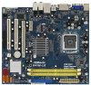
1.5 Motherboard Layout 1 23 4 21.8cm (8.6 in) CPU_FAN1 5 6 FSB1333 Dual Channel DDR2 1066 COM1 32 31 30 29 28 27 DDRII_1 (64 bit, 240-pin module) DDRII_2 (64 bit, 240-pin module) RoHS USB 2.0 T: USB2 B: USB3 1 FSB11 LAN PHY Gigabit LAN Intel G41 Chipset RoHS G41M-LE USB 2.0 T: USB0 - ASRock G41M-LE | User Manual - Page 12
(Pink) USB 2.0 Ports (USB01) USB 2.0 Ports (USB23) VGA/DVI-D Port VGA/D-Sub Port PS/2 Keyboard Port (Purple) * If you use 2-channel Audio Deck" tool on your system. Please follow below instructions according to the OS you install. For Windows® 2000 / XP / XP 64-bit OS: Please click "VIA HD Audio - ASRock G41M-LE | User Manual - Page 13
This is a Micro ATX form factor (9.6" x 8.6", 24.4 x 21.8 cm) motherboard. Before you install the motherboard, study the configuration of your chassis to ensure that the motherboard fits into it. Make sure to unplug the power cord before installing or removing the motherboard. Failure to do - ASRock G41M-LE | User Manual - Page 14
the installation of Intel 775-LAND CPU, please follow the steps below. 775-Pin Socket Overview Before you insert the 775-LAND CPU into the socket, please check if the CPU surface is unclean or if there is any bent pin on the socket. Do not force to insert the CPU into the socket if above situation - ASRock G41M-LE | User Manual - Page 15
to use the cap tab to handle and avoid kicking off the PnP cap. 2. This cap must be placed if returning the motherboard for after service. Step 4. Close the socket: Step 4-1. Rotate the load plate onto the IHS. Step 4-2. While pressing down lightly on load plate, engage the load lever. Step - ASRock G41M-LE | User Manual - Page 16
2.4 Installation of CPU Fan and Heatsink This motherboard is equipped with 775-Pin socket that supports Intel 775-LAND CPU. Please adopt the type of heatsink and cooling fan compliant with Intel 775-LAND CPU to dissipate heat. Before you installed the heatsink, you need to spray thermal interface - ASRock G41M-LE | User Manual - Page 17
2.5 Installation of Memor y Modules (DIMM) G41M-LE motherboard provides two 240-pin DDR2 (Double Data Rate 2) DIMM slots, and supports Dual Channel Memory Technology. For dual channel configuration, you always need to install two identical (the same brand, speed, size and chip-type) memory modules - ASRock G41M-LE | User Manual - Page 18
There are 2 PCI slots and 2 PCI Express slots on this motherboard. PCI slots: PCI slots are used to install expansion cards that Express VGA card to PCIE2 (PCIE x16 slot), the onboard VGA will be disabled. If you install the add-on PCI Express VGA card to PCIE2 (PCIE x16 slot) and adjust the BIOS - ASRock G41M-LE | User Manual - Page 19
2.7 Jumpers Setup The illustration shows how jumpers are setup. When the jumper cap is placed on pins, the jumper is "Short". If no jumper cap is placed on pins, the jumper is "Open". The illustration shows a 3-pin jumper whose pin1 and pin2 are "Short" when jumper cap is placed on these 2 pins. - ASRock G41M-LE | User Manual - Page 20
to FSB1333 (by BIOS setting) you may face the problem, that DRAM frequency will be overclocked very high. Please use jumper to force NB to be strapped at higher frequency, so the DRAM can work at lower frequency. If you want to overclock the CPU you adopt to FSB1066 on this motherboard, you need to - ASRock G41M-LE | User Manual - Page 21
(Blue) (39-pin IDE1, see p.11 No. 8) PIN1 IDE 1 connect the blue end to the motherboard 80-conductor ATA 66/100 cable connect the black end to the IDE devices Note: Please refer to the instruction of your IDE device vendor for the details. Serial ATAII Connectors (SATAII_1: see p.11, No. 14 - ASRock G41M-LE | User Manual - Page 22
panel, there are two USB 2.0 headers on this motherboard. Each USB 2.0 header can support two USB 2.0 ports. (9-pin USB4_5) (see Audio supports Jack Sensing, but the panel wire on the chassis must support HDA to function correctly. Please follow the instruction in our manual and chassis manual to - ASRock G41M-LE | User Manual - Page 23
fan (Quiet Fan) support, the 3-Pin CPU fan still can work successfully even without the fan speed control function. If you plan to connect the 3-Pin CPU fan to the CPU fan connector on this motherboard, please connect it to Pin 1-3. Pin 1-3 Connected 3-Pin Fan Installation ATX Power Connector (24 - ASRock G41M-LE | User Manual - Page 24
Though this motherboard provides 24-pin ATX power connector, it can still work if you adopt a traditional 20-pin ATX power supply. To use the 20-pin ATX power supply, please plug your power supply along with Pin 1 and Pin 13. 12 24 20-Pin ATX Power Supply Installation 1 13 ATX 12V Power - ASRock G41M-LE | User Manual - Page 25
guide. Some default setting of SATAII hard disks may not be at SATAII mode, which operate with the best performance. In order to enable SATAII function, please follow the below instruction website for details: http://www.hitachigst.com/hdd/support/download.htm The above examples are just for your - ASRock G41M-LE | User Manual - Page 26
Technology This motherboard supports Untied Overclocking Technology, which means during overclocking, FSB enjoys better margin due to fixed PCI / PCIE buses. Before you enable Untied Overclocking function, please enter "Overclock Mode" option of BIOS setup to set the selection from [Auto] to [Manual - ASRock G41M-LE | User Manual - Page 27
BIOS FWH chip on the motherboard stores the BIOS SETUP UTILITY. You may run the BIOS SETUP UTILITY when you start up the computer. Please press during the Power-On-Self-Test (POST) to enter the BIOS on. Because the BIOS software is constantly being updated, the following BIOS setup screens and - ASRock G41M-LE | User Manual - Page 28
System Time System Date BIOS Version Processor Type : : [14:00:09] [Thu 10/02/2008] G41M-LE P1.00 Intel(R) CPU 3.20GHz (64bit) 3200MHz F64/4 4096KB Use [Enter], [TAB] or [SHIFT-TAB] to select a field. Use [+] or [-] to configure system Time. Processor Speed : Microcode Update : Cache Size : Total - ASRock G41M-LE | User Manual - Page 29
will pop-out the following message, "Save configuration changes and exit setup?" Select [OK] to save the changes and exit the BIOS SETUP UTILITY. Load BIOS Defaults Load BIOS default values for all the setup questions. F9 key can be used for this operation. Load Performance Setup Default (IDE/SATA - ASRock G41M-LE | User Manual - Page 30
Intel Virtualization tech. CPU Thermal Throttling No-Excute Memory Protection Hyper Threading Technology Intel (R) SpeedStep(tm) tech. +F1 F9 F10 ESC v02.54 (C) Copyright 1985-2005, American Megatrends, Inc. Overclock Mode Use this to select Overclock Mode. Configuration options: [Auto], [Manual - ASRock G41M-LE | User Manual - Page 31
item, which displays the ratio actual value of this motherboard. Enhance Halt State All processors support the Halt State (C1). The C1 state is supported through the native processor instructions HLT and MWAIT and requires no hardware support from the chipset. In the C1 power state, the processor - ASRock G41M-LE | User Manual - Page 32
XP and select [Auto], you need to set the "Power Schemes" as "Portable/Laptop" to enable this function. If you install Windows® VistaTM and want to enable this function, please set this item to [Enabled]. This item will be hidden if the current CPU does not support Intel , the motherboard will detect - ASRock G41M-LE | User Manual - Page 33
DRAM tCL Use this item to adjust the means of memory accessing. Configuration options: [3], [4], [5], [6], [7] and [Auto]. DRAM tRCD This controls the number of DRAM clocks for TRCD. Configuration options: Configuration options: [Auto], [3] to [10]. DRAM tRP This controls the number of DRAM clocks - ASRock G41M-LE | User Manual - Page 34
feature in Intel® 4 Series Express chipset family to support increased content protection motherboard through efficient memory utilization. In DVMT mode, the graphics driver Audio Select [Auto], [Enabled] or [Disabled] for the onboard HD Audio feature. If you select [Auto], the onboard HD Audio - ASRock G41M-LE | User Manual - Page 35
Lan" feature. CPU Voltage Use this to select CPU Voltage. Configuration options: [Auto] and [Manual]. The default of this feature is [Auto]. SB Core Voltage Use this to select SB Core Voltage. Configuration options: [Auto], [1.524V to [Enabled]. Besides the BIOS option, you can also choose our Intelligent - ASRock G41M-LE | User Manual - Page 36
4 . 3 ACPI Configuration BIOS SETUP UTILITY Advanced ACPI Configuration Suspend-to-RAM feature. Select [Auto] will enable this feature if the system supports it. Restore on AC/Power Loss This allows you to set the power state plan to use this motherboard to submit Windows® VistaTM certification. 36 - ASRock G41M-LE | User Manual - Page 37
BIOS SETUP device is used. Set [Enhanced] when Native OS (Win2000 / XP) is used. +F1 F9 F10 ESC Select Screen Select Item Change SATA 4], then SATAII_1, SATAII_3 will not work. Because Intel® ICH7 south bridge only supports four IDE devices under legacy OS (Windows NT), you instruction. 37 - ASRock G41M-LE | User Manual - Page 38
BIOS SETUP UTILITY Advanced Primary IDE Master Device Vendor Size LBA Mode Block Mode PIO Mode Async DMA Ultra DMA S.M.A.R.T. Type LBA/Large Mode Block (Multi-Sector Transfer) PIO Mode DMA Mode S.M.A.R.T. 32Bit Data Transfer :Hard Disk :ST340014A :40.0 GB :Supported hard disk > 512 MB under DOS and - ASRock G41M-LE | User Manual - Page 39
[Enabled]. 32-Bit Data Transfer Use this item to enable 32-bit access to maximize the IDE hard disk data transfer rate. 3.4.5 PCIPnP Configuration BIOS SETUP UTILITY Advanced Advanced PCI / PnP Settings PCI Latency Timer PCI IDE BusMaster [32] [Enabled] Value in units of PCI clocks for PCI device - ASRock G41M-LE | User Manual - Page 40
3.4.6 Floppy Configuration In this section, you may configure the type of your floppy drive. BIOS SETUP UTILITY Advanced Floppy Configuration Floppy A [1.44 MB 31 2"] Select the type of floppy drive connected to the system. +F1 F9 F10 ESC Select Screen Select Item Change Option General Help Load - ASRock G41M-LE | User Manual - Page 41
Parallel Port Address Use this item to set the address for the onboard parallel port or disable it. Configuration options: [Disabled], [378], and [278]. Parallel Port Mode Use this item to set the operation mode of the parallel port. The default value is [ECP+EPP]. If this option is set to [ECP+EPP - ASRock G41M-LE | User Manual - Page 42
this item to enable or disable the USB 2.0 support. Legacy USB Support Use this option to select legacy support for USB devices. There are four configuration options: [Enabled], [Auto], [Disabled] and [BIOS Setup Only]. The default value is [BIOS Setup Only]. Please refer to below descriptions for - ASRock G41M-LE | User Manual - Page 43
you to monitor the status of the hardware on your system, including the parameters of the CPU temperature, motherboard temperature, CPU fan speed, chassis fan speed, and the critical voltage. Main Smart BIOS SETUP UTILITY Advanced H/W Monitor Boot Security Exit Hardware Health Event Monitoring - ASRock G41M-LE | User Manual - Page 44
this section, it will display the available devices on your system for you to configure the boot settings and the boot priority. Main Smart BIOS SETUP UTILITY Advanced H/W Monitor Boot Security Exit Boot Settings Boot Settings Configuration 1st Boot Device 2nd Boot Device 3rd Boot Device 4th Boot - ASRock G41M-LE | User Manual - Page 45
may set or change the supervisor/user password for the system. For the user password, you may also clear it. Main Smart BIOS SETUP UTILITY Advanced H/W Monitor Boot Security Exit Security Settings Supervisor Password : Not Installed User Password : Not Installed Change Supervisor Password Change - ASRock G41M-LE | User Manual - Page 46
and exit setup?" Select [OK] to save the changes and exit the BIOS SETUP UTILITY. Discard Changes and Exit When you select this option, it message, "Discard changes and exit setup?" Select [OK] to exit the BIOS SETUP UTILITY without saving any changes. Discard Changes When you select this option - ASRock G41M-LE | User Manual - Page 47
the necessary drivers to activate the devices. 4 . 2 . 3 Utilities Menu The Utilities Menu shows the applications software that the motherboard supports. Click on a specific item then follow the installation wizard to install it. 4.2.4 Contact Information If you need to contact ASRock or want
-
 1
1 -
 2
2 -
 3
3 -
 4
4 -
 5
5 -
 6
6 -
 7
7 -
8
-
9
-
10
-
11
-
12
-
13
-
14
-
15
-
16
-
17
-
18
-
19
-
20
-
21
-
22
-
23
-
24
-
25
-
26
-
27
-
28
-
29
-
30
-
31
-
32
-
33
-
34
-
35
-
36
-
37
-
38
-
39
-
40
-
41
-
42
-
43
-
44
-
45
-
46
-
47
 |
 |

1
G41M-LE
User Manual
Version 1.0
Published October 2008
Copyright©2008 ASRock INC. All rights reserved.