ASRock G41M-PS User Manual
ASRock G41M-PS Manual
 |
View all ASRock G41M-PS manuals
Add to My Manuals
Save this manual to your list of manuals |
ASRock G41M-PS manual content summary:
- ASRock G41M-PS | User Manual - Page 1
G41M-PS User Manual Version 1.0 Published August 2011 Copyright©2011 ASRock INC. All rights reserved. 1 - ASRock G41M-PS | User Manual - Page 2
any form or by any means, except duplication of documentation by the purchaser for backup purpose, without written consent of ASRock Inc. Products and corporate names appearing in this manual may or may not be registered trademarks or copyrights of their respective companies, and are used only for - ASRock G41M-PS | User Manual - Page 3
2.2 Pre-installation Precautions 13 2.3 CPU Installation 14 2.4 Installation of Heatsink and CPU fan 16 2.5 Installation of Memory Modules 25 2.11 Driver Installation Guide 25 2.12 Untied Overclocking Technology 25 3 BIOS SETUP UTILITY 26 3.1 Introduction 26 3.1.1 BIOS Menu Bar 26 - ASRock G41M-PS | User Manual - Page 4
4 Software Support 52 4.1 Install Operating System 52 4.2 Support CD Information 52 4.2.1 Running Support CD 52 4.2.2 Drivers Menu 52 4.2.3 Utilities Menu 52 4.2.4 Contact Information 52 4 - ASRock G41M-PS | User Manual - Page 5
guide to BIOS setup and information of the Support CD. Because the motherboard specifications and the BIOS software might be updated, the content of this manual will be subject to change without notice. In case any modifications of this manual occur, the updated version will be available on ASRock - ASRock G41M-PS | User Manual - Page 6
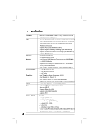
with max. resolution up to 2048x1536 @ 60Hz - 5.1 CH HD Audio (VIA® VT1705 Audio Codec) - PCIE x1 Gigabit LAN 10/100/1000 Mb/s - Atheros® AR8151 - Supports Wake-On-LAN - Supports LAN Cable Detection - Supports PXE I/O Panel - 1 x PS/2 Mouse Port - 1 x PS/2 Keyboard Port - 1 x Parallel Port (ECP/EPP - ASRock G41M-PS | User Manual - Page 7
power connector - Front panel audio connector - 2 x USB 2.0 headers (support 4 USB 2.0 ports) - 8Mb AMI BIOS - AMI Legal BIOS - Supports "Plug and Play" - ACPI 1.1 Compliance Wake Up Events - AMBIOS 2.3.1 Support - DRAM, NB, SB, VTT Voltage Multi-adjustment - Drivers, Utilities, AntiVirus Software - ASRock G41M-PS | User Manual - Page 8
guide of memory modules on page 17 for proper installation. 4. Please check the table below for the CPU FSB frequency and its corresponding memory support frequency. CPU FSB Frequency Memory Support Frequency 1333 DDR3 800, DDR3 1066, DDR3 1333 1066 DDR3 800, DDR3 1066 800 DDR3 - ASRock G41M-PS | User Manual - Page 9
40% faster than before. ASRock APP Charger allows you to quickly charge many Apple devices simultaneously and even supports continuous charging when your PC enters into Standby mode (S1), Suspend to RAM (S3), hibernation mode (S4) or power off (S5). With APP Charger driver installed, you can easily - ASRock G41M-PS | User Manual - Page 10
for a more personal Internet experience. ASRock motherboards are exclusively equipped with the SmartView : You can watch Youtube HD video and download files simultaneously. Real-Time Analysis of Your dissipation, remember to spray thermal grease between the CPU and the heatsink when you install the PC - ASRock G41M-PS | User Manual - Page 11
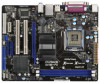
Intel G41 Chipset PCIE1 Designed in Taipei Super IO PCI1 HD_AUDIO1 1 RoHS PCI2 AUDIO CODEC CLRCMOS1 PCIE2 FLOPPY1 USB6_7 1 USB4_5 1 SATAII_4 SATAII_3 CHA_FAN1 SATAII_2 SATAII_1 G41M-PS Intel ICH7 8Mb BIOS IDE1 SPEAKER1 1 PLED PWRBTN 1 HDLED RESET PANEL 1 20 19 18 17 1615 14 - ASRock G41M-PS | User Manual - Page 12
(USB01) 8 USB 2.0 Ports (USB23) 9 VGA Port 10 COM Port 11 PS/2 Keyboard Port (Purple) * There are two LED next to the LAN port. audio cable to the front panel audio header. After restarting your computer, you will find "VIA HD Audio Deck" tool on your system. Please follow below instructions - ASRock G41M-PS | User Manual - Page 13
Chapter 2 Installation G41M-PS is a Micro ATX form factor (9.6" x 7.5", 24.4 x 19.1 cm) motherboard. Before you install the motherboard, study the configuration of your chassis to ensure that the motherboard - ASRock G41M-PS | User Manual - Page 14
Rotate the load plate to fully open position at approximately 100 degrees. Step 2. Insert the 775-LAND CPU: Step 2-1. Hold the CPU by the edges where are marked with black lines. Step 2-2. Orient the CPU with IHS (Integrated Heat Sink) up. Locate Pin1 and the two orientation key notches. Pin1 - ASRock G41M-PS | User Manual - Page 15
CPU is within the socket and properly mated to the orient keys. Step 3. Remove PnP Cap (Pick and Place Cap): Use your left hand index finger and thumb to support . 2. This cap must be placed if returning the motherboard for after service. Step 4. Close the socket: Step 4-1. Rotate the load plate onto - ASRock G41M-PS | User Manual - Page 16
are securely fastened and in good contact with each other. Then connect the CPU fan to the CPU_FAN connector (CPU_FAN1, see page 11, No. 3). For proper installation, please kindly refer to the instruction manuals of your CPU fan and heatsink. Below is an example to illustrate the installation of the - ASRock G41M-PS | User Manual - Page 17
2.5 Installation of Memory Modules (DIMM) G41M-PS motherboard provides two 240-pin DDR3 (Double Data Rate 3) DIMM slots, and supports Dual Channel Memory Technology. For dual channel configuration, you always need to install two identical (the same brand, speed, size and chip-type) memory modules - ASRock G41M-PS | User Manual - Page 18
slot), the onboard VGA will be disabled. If you install the add-on PCI Express VGA card to PCIE1 (PCIE x16 slot) and adjust the BIOS options "Primary Graphics Adapter" to [Onboard] and "Share Memory" to [Auto], then the onboard VGA will be enabled, and the primary screen will be onboard - ASRock G41M-PS | User Manual - Page 19
to short 2 pins on CLRCMOS1 for 5 seconds. EUP LAN / EUP Audio Jumper (EUP_LAN1, 3-pin jumper, see p.11 No. 25) (EUP_AUDIO1, to meet EuP standard. With an ASRock EuP ready motherboard and a power supply Wake-On-LAN function under S3 (Suspend to RAM), S4 (Suspend to Disk), and S5 - ASRock G41M-PS | User Manual - Page 20
FSB1, 3-pin jumper, see p.11 No. 27) FSB1 Default If you adopt FSB1333-CPU and DDR3 1333 memory module on this motherboard, you need to adjust the jumper. Please short pin2, pin3 for FSB1 jumper. Otherwise, the CPU and memory module may not work properly on this motherboard. Please refer to below - ASRock G41M-PS | User Manual - Page 21
devices 80-conductor ATA 66/100 cable Note: Please refer to the instruction of your IDE device vendor for the details. Serial ATAII Connectors ( ) SATAII_4 SATAII_2 SATAII_3 SATAII_1 These Serial ATAII (SATAII) connectors support SATAII or SATA hard disk for internal storage devices. The current - ASRock G41M-PS | User Manual - Page 22
cable that allows convenient connection and control of audio devices. 1. High Definition Audio supports Jack Sensing, but the panel wire on the chassis must support HDA to function correctly. Please follow the instruction in our manual and chassis manual to install your system. 2. If you use AC - ASRock G41M-PS | User Manual - Page 23
to the ground pin. 1 2 3 4 Though this motherboard provides 4-Pin CPU fan (Quiet Fan) support, the 3-Pin CPU fan still can work successfully even without the fan speed control function. If you plan to connect the 3-Pin CPU fan to the CPU fan connector on this motherboard, please connect it to Pin - ASRock G41M-PS | User Manual - Page 24
guide. Some default setting of SATAII hard disks may not be at SATAII mode, which operate with the best performance. In order to enable SATAII function, please follow the below instruction website for details: http://www.hitachigst.com/hdd/support/download.htm The above examples are just for your - ASRock G41M-PS | User Manual - Page 25
supports Untied Overclocking Technology, which means during overclocking, FSB enjoys better margin due to fixed PCI / PCIE buses. Before you enable Untied Overclocking function, please enter "Overclock Mode" option of BIOS setup to set the selection from [Auto] to [Manual]. Therefore, CPU - ASRock G41M-PS | User Manual - Page 26
the reset button on the system chassis. You may also restart by turning the system off and then back on. Because the BIOS software is constantly being updated, the following BIOS setup screens and descriptions are for reference purpose only, and they may not exactly match what you see on your screen - ASRock G41M-PS | User Manual - Page 27
Overview System Time System Date [14:00:09] [Mon 08/15/2011] BIOS Version : G41M-PS P1.00 Processor Type : Intel (R) Pentium (R) Dual CPU E2220 @ 2.40GHz (64bit) Processor Speed : 2400MHz Microcode Update : 6FB/A3 Cache Size : 1024KB Total Memory DDR3_A1 DDR3_A2 : 1024MB Single-Channel - ASRock G41M-PS | User Manual - Page 28
set up overclocking features. BIOS SETUP UTILITY Main OC Tweaker Advanced H/W Monitor Boot Security Exit OC Tweaker Settings Load CPU EZ OC Setting [Disabled CPU and memory module you adopt on this motherboard. Please refer to page 8 for the CPU FSB frequency and its corresponding memory support - ASRock G41M-PS | User Manual - Page 29
DRAM Timing Configuration BIOS SETUP UTILITY OC Tweaker DRAM Timing Control DRAM tCL 6 DRAM tRCD 6 DRAM tRP 6 DRAM tRAS 15 DRAM tRFC 44 DRAM tWR 6 DRAM tWTR 4 DRAM tRRD 3 - ASRock G41M-PS | User Manual - Page 30
to allow you changing the ratio value of this motherboard. If the CPU you adopt supports EIST (Intel (R) SpeedStep(tm) tech.), and you plan to adjust the Configuration options: [Auto], [Manual], and [Optimized]. The default value is [Auto]. If you select [Manual], Untied Overclocking function is - ASRock G41M-PS | User Manual - Page 31
DRAM Voltage Use this to select DRAM Voltage. The default value of this feature is [Auto]. NB Voltage Use this to select NB Voltage. The default value of this feature is [Auto]. VTT Voltage Use this to select VTT Voltage. The default value of this feature is [Auto]. GLTREF Voltage Use this to select - ASRock G41M-PS | User Manual - Page 32
Chipset Configuration ACPI Configuration Storage Configuration PCIPnP Configuration Floppy Configuration SuperIO Configuration USB Configuration BIOS Update Utility ASRock Instant Flash Good Night LED [Disabled] Options for CPU Select Screen Select Item Enter Go to Sub Screen F1 General Help F9 - ASRock G41M-PS | User Manual - Page 33
Configuration BIOS SETUP UTILITY Advanced CPU Configuration Overclock Mode CPU Frequency [Manual], and [Optimized]. The default value is [Auto]. If you select [Manual], changing the ratio value of this motherboard. If the CPU you adopt supports EIST (Intel (R) SpeedStep(tm) tech.), and you - ASRock G41M-PS | User Manual - Page 34
(C1). The C1 state is supported through the native processor instructions HLT and MWAIT and requires no hardware support from the chipset. In the execute code. This option will be hidden if the current CPU does not support No-Excute Memory Protection. Hyper Threading Technology To enable this - ASRock G41M-PS | User Manual - Page 35
On-Demand Clock Modulation This provides the On-Demand Clock Modulation duty cycle. It indicates the clock on to clock off interval ratio. For example, if you set this option to [75.0% On], your processor will work normally 75% of the time, and spend the other 25% slacking off. Configuration options - ASRock G41M-PS | User Manual - Page 36
[PCI] [Auto] [Disabled] [DVMT Mode] [Maximum DVMT] Onboard HD Audio Front Panel OnBoard Lan [Auto] [Auto] [Enabled] +F1 F9 F10 ESC Copyright 1985-2005, American Megatrends, Inc. DRAM RCOMP and tRD Configuration BIOS SETUP UTILITY Advanced DRAM RCOMP STRENGTH Settings DRAM CH0 RCOMP Settings : - ASRock G41M-PS | User Manual - Page 37
DRAM CH0 G3 (Control2) This controls the number of DRAM CH0 G3 (Control2). Min: 1. Max: 15. The default value is [Auto]. DRAM CH0 G4 (Clocks1) This controls the number of DRAM CH0 G4 (Clocks1). Min: 1. Max: 15. The default value is [Auto]. DRAM CH0 G5 (Clocks2) This controls the number of DRAM CH0 - ASRock G41M-PS | User Manual - Page 38
DRAM DLL SKEW Configuration BIOS SETUP UTILITY Advanced DRAM DLL SKEW Settings DRAM CH0 CLKSET0 SKEW Info:0-0-0-0-0-0 DRAM CH0 CLKSET0 SKEW [Auto] DRAM CH0 CLKSET1 SKEW Info:0-0-0-0-0-0 DRAM CH0 CLKSET1 - ASRock G41M-PS | User Manual - Page 39
enable this function, please set this item to [Enabled]. Besides the BIOS option, you can also choose our Intelligent Energy Saver utility to graphics feature in Intel® 4 Series Express chipset family to support increased content protection and robustness requirements for premium content playback ( - ASRock G41M-PS | User Manual - Page 40
not be used under Windows® VistaTM OS because the driver will intelligently detect physical memory available and allocate necessary video Audio Select [Auto], [Enabled] or [Disabled] for the onboard HD Audio feature. If you select [Auto], the onboard HD Audio will be disabled when PCI Sound Card - ASRock G41M-PS | User Manual - Page 41
3ACPI Configuration BIOS SETUP UTILITY Advanced ACPI Configuration Suspend To RAM Check Ready Bit Restore on AC/Power Loss Ring-In Power On PCI Devices Power On PS / 2 toRAM feature. Select [Auto] will enable this feature if the OS supports it. Check Ready Bit Use this item to enable or disable the - ASRock G41M-PS | User Manual - Page 42
3.4.4Storage Configuration BIOS SETUP UTILITY Advanced Storage Configuration ATA/IDE [PATA Only], then all SATAII will not work, only IDE will work. Because Intel® ICH7 south bridge only supports four IDE devices under legacy OS (Windows NT), you have to choose [SATA 1, SATA 2, SATA 3, SATA - ASRock G41M-PS | User Manual - Page 43
the "Primary IDE Master" as the example in the following instruction. BIOS SETUP UTILITY Advanced Primary IDE Master Device Vendor Size LBA Mode 32Bit Data Transfer :Hard Disk :ST340014A :40.0 GB :Supported :16Sectors :4 :MultiWord DMA-2 :Ultra DMA-5 :Supported [Auto] [Auto] [Auto] [Auto] [Auto] - ASRock G41M-PS | User Manual - Page 44
Enabled]. 32-Bit Data Transfer Use this item to enable 32-bit access to maximize the IDE hard disk data transfer rate. 3.4.5PCIPnP Configuration BIOS SETUP UTILITY Advanced Advanced PCI / PnP Settings PCI Latency Timer PCI IDE BusMaster [32] [Enabled] Value in units of PCI clocks for PCI device - ASRock G41M-PS | User Manual - Page 45
Port Address Parallel Port Mode EPP Version ECP Mode DMA Channel Parallel Port IRQ [Enabled] [3F8 / IRQ4] [378] [ECP + EPP] [1.9] [DMA3] [IRQ7] Allow BIOS to Enable or Disable Floppy Controller. +F1 F9 F10 ESC Select Screen Select Item Change Option General Help Load Defaults Save and Exit Exit - ASRock G41M-PS | User Manual - Page 46
Parallel Port Address Use this item to set the address for the onboard parallel port or disable it. Configuration options: [Disabled], [378], and [278]. Parallel Port Mode Use this item to set the operation mode of the parallel port. The default value is [ECP+EPP]. If this option is set to [ECP+EPP - ASRock G41M-PS | User Manual - Page 47
Use this item to enable or disable the USB 2.0 support. Legacy USB Support Use this option to select legacy support for USB devices. There are four configuration options: [Enabled], [Auto], [Disabled] and [BIOS Setup Only]. The default value is [Enabled]. Please refer to below descriptions for - ASRock G41M-PS | User Manual - Page 48
to monitor the status of the hardware on your system, including the parameters of the CPU temperature, motherboard temperature, CPU fan speed, chassis fan speed, and the critical voltage. BIOS SETUP UTILITY Main OC Tweaker Advanced H/W Monitor Boot Security Exit Hardware Health Event Monitoring - ASRock G41M-PS | User Manual - Page 49
this section, it will display the available devices on your system for you to configure the boot settings and the boot priority. BIOS SETUP UTILITY Main OC Tweaker Advanced H/W Monitor Boot Security Exit Boot Settings Boot Settings Configuration Configure Settings during System Boot. 1st Boot - ASRock G41M-PS | User Manual - Page 50
this section, you may set or change the supervisor/user password for the system. For the user password, you may also clear it. BIOS SETUP UTILITY Main OC Tweaker Advanced H/W Monitor Boot Security Exit Security Settings Supervisor Password : Not Installed User Password : Not Installed Change - ASRock G41M-PS | User Manual - Page 51
. Discard Changes When you select this option, it will pop-out the following message, "Discard changes?" Select [OK] to discard all changes. Load BIOS Defaults Load BIOS default values for all the setup questions. F9 key can be used for this operation. Load Performance Setup Default (IDE/SATA) This - ASRock G41M-PS | User Manual - Page 52
install the necessary drivers to activate the devices. 4.2.3 Utilities Menu The Utilities Menu shows the applications software that the motherboard supports. Click on a specific item then follow the installation wizard to install it. 4.2.4 Contact Information If you need to contact ASRock or want to
-
 1
1 -
 2
2 -
 3
3 -
 4
4 -
 5
5 -
 6
6 -
 7
7 -
8
-
9
-
10
-
11
-
12
-
13
-
14
-
15
-
16
-
17
-
18
-
19
-
20
-
21
-
22
-
23
-
24
-
25
-
26
-
27
-
28
-
29
-
30
-
31
-
32
-
33
-
34
-
35
-
36
-
37
-
38
-
39
-
40
-
41
-
42
-
43
-
44
-
45
-
46
-
47
-
48
-
49
-
50
-
51
-
52
 |
 |

1
G41M-PS
User Manual
Version 1.0
Published August 2011
Copyright©2011 ASRock INC. All rights reserved.