ASRock G41M-S User Manual
ASRock G41M-S Manual
 |
View all ASRock G41M-S manuals
Add to My Manuals
Save this manual to your list of manuals |
ASRock G41M-S manual content summary:
- ASRock G41M-S | User Manual - Page 1
G41M-S User Manual Version 1.1 Published July 2009 Copyright©2009 ASRock INC. All rights reserved. 1 - ASRock G41M-S | User Manual - Page 2
purchaser for backup purpose, without written consent of ASRock Inc. Products and corporate names appearing in this manual may or may not be registered trademarks or copyrights USA ONLY The Lithium battery adopted on this motherboard contains Perchlorate, a toxic substance controlled in Perchlorate - ASRock G41M-S | User Manual - Page 3
and CPU fan 15 2.5 Installation of Memory Modules (DIMM 16 2.6 Expansion Slots (PCI and PCI Express Slots 17 2.7 Jumpers Setup 18 2.8 Onboard Headers and Connectors 20 2.9 SATAII Hard Disk Setup Guide 24 2.10 Serial ATA (SATA) / Serial ATAII (SATAII) Hard Disks Installation 25 2.11 Driver - ASRock G41M-S | User Manual - Page 4
4 Software Support 50 4.1 Install Operating System 50 4.2 Support CD Information 50 4.2.1 Running Support CD 50 4.2.2 Drivers Menu 50 4.2.3 Utilities Menu 50 4.2.4 Contact Information 50 4 - ASRock G41M-S | User Manual - Page 5
specific information about the model you are using. www.asrock.com/support/index.asp 1.1 Package Contents ASRock G41M-S Motherboard (Micro ATX Form Factor: 9.6-in x 7.6-in, 24.4 cm x 19.3 cm) ASRock G41M-S Quick Installation Guide ASRock G41M-S Support CD One 80-conductor Ultra ATA 66/100 IDE Ribbon - ASRock G41M-S | User Manual - Page 6
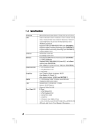
Specifications Platform CPU Chipset Memory Expansion Slot Graphics Audio LAN Rear Panel I/O - Micro ATX Form Factor: 9.6-in x 7.6-in, 24.4 cm x 19.3 cm - LGA 775 for Intel® CoreTM 2 Extreme / CoreTM 2 Quad / CoreTM 2 Duo / Pentium® Dual Core / Celeron® Dual Core / Celeron®, supporting Penryn Quad - ASRock G41M-S | User Manual - Page 7
2.0 ports) (see CAUTION 9) BIOS Feature - 8Mb AMI BIOS - AMI Legal BIOS - Supports "Plug and Play" - ACPI 1.1 Compliance Wake Up Events - AMBIOS 2.3.1 Support - Supports Smart BIOS Support CD - Drivers, Utilities, AntiVirus Software (Trial Version) Unique Feature - ASRock OC Tuner (see - ASRock G41M-S | User Manual - Page 8
jumper settings. 2. About the setting of "Hyper Threading Technology", please check page 31. 3. This motherboard supports Untied Overclocking Technology. Please read "Untied Overclocking Technology" on page 25 for details. 4. This motherboard supports Dual Channel Memory Technology. Before - ASRock G41M-S | User Manual - Page 9
of Intelligent Energy Saver. ASRock website: http://www.asrock.com 12. ASRock Instant Flash is a BIOS flash utility embedded in Flash ROM. This convenient BIOS update tool allows you to update system BIOS without entering operating systems first like MS-DOS or Windows®. With this utility, you - ASRock G41M-S | User Manual - Page 10
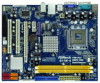
PCI1 Intel ICH7 PCI2 CHA_FAN1 8Mb BIOS PLED PWRBTN 1 1 HDLED RESET PANEL 1 USB4_5 USB6_7 1 SPEAKER1 1 SATAII_1 20 19 18 17 16 15 14 13 12 G41M-S SATAII_2 SATAII_4 24.4cm (9.6 in) 6 7 8 9 10 11 1 PS2_USB_PWR1 Jumper 16 USB 2.0 Header (USB4_5, Blue) 2 775-Pin CPU Socket 17 - ASRock G41M-S | User Manual - Page 11
to connect a front panel audio cable to the front panel audio header. Please refer to below steps for the software setting of Multi-Streaming. For Windows® XP: After restarting your computer, you will find "Mixer" tool on your system. Please select "Mixer ToolBox" , click "Enable playback multi - ASRock G41M-S | User Manual - Page 12
Installation G41M-S is a Micro ATX form factor (9.6" x 7.6", 24.4 x 19.3 cm) motherboard. Before you install the motherboard, study the configuration of your chassis to ensure that the motherboard fits into it. Make sure to unplug the power cord before installing or removing the motherboard. Failure - ASRock G41M-S | User Manual - Page 13
the installation of Intel 775-LAND CPU, please follow the steps below. 775-Pin Socket Overview Before you insert the 775-LAND CPU into the socket, please check if the CPU surface is unclean or if there is any bent pin on the socket. Do not force to insert the CPU into the socket if above situation - ASRock G41M-S | User Manual - Page 14
CPU with the two alignment keys of the socket. Step 2-3. Carefully place the CPU into the socket by using a purely vertical motion. Step 2-4. Verify that the CPU is within the socket must be placed if returning the motherboard for after service. Step 4. Close the socket: Step 4-1. Rotate the load - ASRock G41M-S | User Manual - Page 15
Heatsink This motherboard is equipped with 775-Pin socket that supports Intel 775-LAND CPU. Please adopt the type of heatsink and cooling fan compliant with Intel 775-LAND CPU to dissipate heat. Before you installed the heatsink, you need to spray thermal interface material between the CPU and the - ASRock G41M-S | User Manual - Page 16
2.5 Installation of Memory Modules (DIMM) G41M-S motherboard provides two 240-pin DDR2 (Double Data Rate 2) DIMM slots, and supports Dual Channel Memory Technology. For dual channel configuration, you always need to install two identical (the same brand, speed, size and chip-type) memory modules in - ASRock G41M-S | User Manual - Page 17
add-on PCI Express VGA card to PCIE2 (PCIE x16 slot) and adjust the BIOS options "Primary Graphics Adapter" to [Onboard] and "Share Memory" to [Auto Please read the documentation of the expansion card and make necessary hardware settings for the card before you start the installation. Step 2. Remove - ASRock G41M-S | User Manual - Page 18
ASRock EuP ready motherboard and a power supply that the 5VSB power efficiency is higher than 50% under 100mA current consumption, your system is able to submit EuP standard. The default setting that when EUP_LAN jumper is set to enabled, the Wake-On-LAN function under S3 (Suspend to RAM), S4 - ASRock G41M-S | User Manual - Page 19
: If you adopt below DRAM / CPU configuration on this motherboard, you need to adjust the jumpers. Please follow the instructions below to set up the jumpers. Otherwise, the CPU and memory module may not work properly on this motherboard. DRAM CPU Jumper Settings DDR2 533 FSB533 FSB1 FSB2 FSB3 - ASRock G41M-S | User Manual - Page 20
, see p.10 No. 7) PIN1 IDE1 connect the blue end connect the black end to the motherboard to the IDE devices 80-conductor ATA 66/100 cable Note: Please refer to the instruction of your IDE device vendor for the details. SATAII_1 SATAII_3 SATAII_2 SATAII_4 Serial ATAII Connectors (SATAII_1 - ASRock G41M-S | User Manual - Page 21
allows convenient connection and control of audio devices. 1. High Definition Audio supports Jack Sensing, but the panel wire on the chassis must support HDA to function correctly. Please follow the instruction in our manual and chassis manual to install your system. 2. If you use AC'97 audio - ASRock G41M-S | User Manual - Page 22
/ XP / XP 64-bit OS: Please select "Front Mic" as default record device. If you want to hear your voice through front mic, please deselect "Mute" icon in "Front Mic" of "Playback" portion. For Windows® VistaTM / VistaTM 64-bit OS: Go to the "Front Mic" Tab in the Realtek Control panel. Click "Set - ASRock G41M-S | User Manual - Page 23
(see p.10 No. 6) 12 24 Please connect an ATX power supply to this connector. 1 13 Though this motherboard provides 24-pin ATX power connector, 12 24 it can still work if you adopt a traditional 20-pin ATX power supply. To use the 20-pin ATX power supply, please plug your power supply along - ASRock G41M-S | User Manual - Page 24
guide. Some default setting of SATAII hard disks may not be at SATAII mode, which operate with the best performance. In order to enable SATAII function, please follow the below instruction website for details: http://www.hitachigst.com/hdd/support/download.htm The above examples are just for your - ASRock G41M-S | User Manual - Page 25
Technology This motherboard supports Untied Overclocking Technology, which means during overclocking, FSB enjoys better margin due to fixed PCI / PCIE buses. Before you enable Untied Overclocking function, please enter "Overclock Mode" option of BIOS setup to set the selection from [Auto] to [Manual - ASRock G41M-S | User Manual - Page 26
on. Because the BIOS software is constantly being updated, the following BIOS setup screens and descriptions set up the system time/date information Smart To load the BIOS according to your requirements Advanced To set up the advanced BIOS features PCIPnP To set up the PCI features Boot To set - ASRock G41M-S | User Manual - Page 27
settings To save changes and exit the BIOS BIOS Version : G41M-S P1.00 Processor Type : Intel(R) CPU 3.20GHz (64bit) Processor Speed : 3200MHz Microcode Update : F64/4 Cache Size : 4096KB Total Memory DDRII1 DDRII2 : 1024MB with 128MB shared memory and 2MB GTT memory Single-Channel Memory - ASRock G41M-S | User Manual - Page 28
Defaults Load Performance Setup Default (IDE/SATA) Load Power Saving Setup Default BIOS Update Utility ASRock Instant Flash EZ Overclocking Load Optimized CPU OC Setting [Press Enter] Exit system setup after saving the changes. F10 key can be used for this operation. Select Screen Select Item Enter - ASRock G41M-S | User Manual - Page 29
appears when you adopt E5000 series CPU. You can use this option to load the optiomized CPU overclocking setting. Configuration options: [2.64 GHz], [2.88 GHz], [3.00 GHz], [3.12 GHz] and [3.27 GHz]. Please note that overclocing may cause damage to your CPU and motherboard. It should be done at your - ASRock G41M-S | User Manual - Page 30
Overclock Mode CPU Frequency (MHz) PCIE Frequency (MHz) Boot Failure Guard Spread Spectrum [Auto] [200] [100] [Enabled] [Auto] Ratio Status Ratio Actual Value Ratio CMOS Setting Unlocked (Min: 12, Max: 14) 14 [14] Intel (R) Virtualization tech. CPU Thermal Throttling No-Excute Memory - ASRock G41M-S | User Manual - Page 31
No-Excute Memory Protection. Hyper Threading Technology To enable this feature, it requires a computer system with an Intel Pentium® 4 processor that supports Hyper-Threading technology and an operating system that includes optimization for this technology, such as Microsoft® Windows® XP. Set to - ASRock G41M-S | User Manual - Page 32
module you adopt on this motherboard. Please refer to page 8 for the CPU FSB frequency and its corresponding memory support frequency. Flexibility Option The default value of this option is [Disabled]. It will allow better tolerance for memory compatibility when it is set to [Enabled]. DRAM tCL Use - ASRock G41M-S | User Manual - Page 33
DRAM tWR This controls the number of DRAM clocks for TWR. Min: 3. Max: 15. The default value is [Auto]. DRAM tWTR This controls the number of DRAM clocks for TWTR. Min: 2. Max: 15. The default value is [Auto]. DRAM tRRD This controls the number of DRAM clocks for TRRD. Min: 2. Max: 15. The default - ASRock G41M-S | User Manual - Page 34
DRAM RCOMP STRENGTH Configuration BIOS SETUP UTILITY Advanced DRAM RCOMP STRENGTH Settings DRAM CH0 RCOMP STRENGTH Info : 0-10-7-7-7-7 DRAM CH0 G0 (Data) [Auto] DRAM CH0 G1 (Command) [Auto] DRAM CH0 G2 (Control1) [Auto] DRAM CH0 G3 (Control2) - ASRock G41M-S | User Manual - Page 35
DRAM CH1 G3 (Control2) This controls the number of DRAM CH1 G3 (Control2). Min: 1. Max: 15. The default value is [Auto]. DRAM CH1 G4 (Clocks1) This controls the number of DRAM CH1 G4 (Clocks1). Min: 1. Max: 15. The default value is [Auto]. DRAM CH1 G5 (Clocks2) This controls the number of DRAM CH1 - ASRock G41M-S | User Manual - Page 36
DRAM DLL SKEW Settings BIOS SETUP UTILITY Advanced DRAM DLL SKEW Settings DRAM CH0 CLKSET0 SKEW Info:0-0-0-0-0-0 DRAM CH0 CLKSET0 SKEW [Auto] DRAM CH0 CLKSET1 SKEW Info:0-0-0-0-0-0 DRAM CH0 CLKSET1 SKEW [Auto] DRAM CH0 CMD SKEW Info :0-0-0-0-0-0-0 - ASRock G41M-S | User Manual - Page 37
DRAM CH1 CMD SKEW This controls the number of DRAM CH1 CMD SKEW. The default value is [Auto]. DRAM CH1 CTRL0 SKEW This controls the number of DRAM CH1 CTRL0 SKEW. The default value is [Auto]. DRAM CH1 CTRL1 SKEW This controls the number of DRAM CH1 CTRL1 SKEW. The default value is [Auto]. DRAM CH1 - ASRock G41M-S | User Manual - Page 38
. This item will not be used under Windows® VistaTM OS because the driver will intelligently detect physical memory available and allocate necessary video memory. DVMT/FIXED Memory You are allowed to adjust the shared memory size in this item if you set DVMT Mode Select as [DVMT Mode]. Configuration - ASRock G41M-S | User Manual - Page 39
delivers unparalleled power savings. The default value is [Disabled]. Configuration options: [Enabled] and [Disabled]. If you want to enable this function, please set this item to [Enabled]. Besides the BIOS option, you can also choose our Intelligent Energy Saver utility to enable this function. 39 - ASRock G41M-S | User Manual - Page 40
BIOS SETUP UTILITY Advanced ACPI Configuration Suspend To RAM Repost Video on STR Resume Check Ready Bit Restore on AC/Power Loss Ring-In Power On PCI feature. Select [Auto] will enable this feature if the OS supports it. If you set this item to [Disabled], the function "Repost Video on STR - ASRock G41M-S | User Manual - Page 41
or disable ACPI HPET Table. The default value is [Disabled]. Please set this option to [Enabled] if you plan to use this motherboard to submit Windows® VistaTM certification. 3.4.4 IDE Configuration BIOS SETUP UTILITY Advanced IDE Configuration ATA/IDE Configuration SATAII_1 SATAII_2 SATAII_3 - ASRock G41M-S | User Manual - Page 42
set the IDE configuration for the device that you specify. We will use the "Primary IDE Master" as the example in the following instruction. BIOS .0 GB :Supported :16Sectors :4 :MultiWord DMA-2 :Ultra DMA-5 :Supported [Auto] disk > 512 MB under DOS and Windows; for Netware and UNIX user, select - ASRock G41M-S | User Manual - Page 43
to maximize the IDE hard disk data transfer rate. 3.4.5 PCIPnP Configuration BIOS SETUP UTILITY Advanced Advanced PCI / PnP Settings PCI Latency Timer PCI IDE BusMaster [32] [Enabled] Value in units of PCI clocks for PCI device latency timer register. +F1 F9 F10 ESC Select Screen Select Item - ASRock G41M-S | User Manual - Page 44
DMA Channel Parallel Port IRQ [Enabled] [3F8 / IRQ4] [378] [ECP + EPP] [1.9] [DMA3] [IRQ7] Allow BIOS to Enable or Disable to enable or disable floppy drive controller. Serial Port Address Use this item to set the address for the onboard serial port or disable it. Configuration options: [Disabled - ASRock G41M-S | User Manual - Page 45
], [DMA1], and [DMA3]. Parallel Port IRQ Use this item to set the IRQ for the parallel port. Configuration options: [IRQ5] and [IRQ7]. 3.4.8 USB Configuration BIOS SETUP UTILITY Advanced USB Configuration USB Controller USB 2.0 Support Legacy USB Support [Enabled] [Enabled] [Enabled] To enable - ASRock G41M-S | User Manual - Page 46
allowed to use only under BIOS setup and Windows / Linux OS. 3.5 Hardware Health Event Monitoring Screen In this section, it allows you to monitor the status of the hardware on your system, including the parameters of the CPU temperature, motherboard temperature, CPU fan speed, chassis fan speed - ASRock G41M-S | User Manual - Page 47
Copyright 1985-2005, American Megatrends, Inc. 3.6.1 Boot Settings Configuration BIOS SETUP UTILITY Boot Boot Settings Configuration Full Screen Logo AddOn ROM Display Boot Logo ], [S series], [Scenery] and [ASRock]. The default value is [Auto]. Currently, the option [Auto] is set to Aircraft. 47 - ASRock G41M-S | User Manual - Page 48
the supervisor/user password for the system. For the user password, you may also clear it. BIOS SETUP UTILITY Main Smart Advanced H/W Monitor Boot Security Exit Security Settings Supervisor Password : Not Installed User Password : Not Installed Change Supervisor Password Change User Password - ASRock G41M-S | User Manual - Page 49
3.8 Exit Screen BIOS SETUP UTILITY Main Smart Advanced H/W Monitor Boot Security Exit Exit Options Save Changes and Exit Discard Changes and Exit Discard Changes Would you like to save current setting user defaults ? Save 1st User Defaults Load 1st User Defaults Save 2nd User Defaults Load 2nd - ASRock G41M-S | User Manual - Page 50
4.1 Install Operating System This motherboard supports various Microsoft® Windows® operating systems: 2000 / XP / XP 64-bit / VistaTM / VistaTM 64-bit. Because motherboard settings and hardware options vary, use the setup procedures in this chapter for general reference only. Refer to your OS
-
 1
1 -
 2
2 -
 3
3 -
 4
4 -
 5
5 -
 6
6 -
 7
7 -
8
-
9
-
10
-
11
-
12
-
13
-
14
-
15
-
16
-
17
-
18
-
19
-
20
-
21
-
22
-
23
-
24
-
25
-
26
-
27
-
28
-
29
-
30
-
31
-
32
-
33
-
34
-
35
-
36
-
37
-
38
-
39
-
40
-
41
-
42
-
43
-
44
-
45
-
46
-
47
-
48
-
49
-
50
 |
 |

1
G41M-S
User Manual
Version 1.
1
Published Ju
ly
2009
Copyright©2009 ASRock INC. All rights reserved.