ASRock G41MH-GE User Manual
ASRock G41MH-GE Manual
 |
View all ASRock G41MH-GE manuals
Add to My Manuals
Save this manual to your list of manuals |
ASRock G41MH-GE manual content summary:
- ASRock G41MH-GE | User Manual - Page 1
G41MH-GE User Manual Version 1.0 Published September 2009 Copyright©2009 ASRock INC. All rights reserved. 1 - ASRock G41MH-GE | User Manual - Page 2
purchaser for backup purpose, without written consent of ASRock Inc. Products and corporate names appearing in this manual may or may not be registered trademarks or copyrights USA ONLY The Lithium battery adopted on this motherboard contains Perchlorate, a toxic substance controlled in Perchlorate - ASRock G41MH-GE | User Manual - Page 3
for Full HD 1080p Blu-ray (BD) / HD-DVD Playback Support 10 1.4 Motherboard Layout 11 1.5 I/O Panel 12 2 Installation 13 2.1 Screw Holes 13 2.2 Pre-installation Precautions 13 2.3 CPU Installation 14 2.4 Installation of Heatsink and CPU fan 16 2.5 Installation of Memory Modules (DIMM 17 - ASRock G41MH-GE | User Manual - Page 4
53 3.6 Boot Screen 54 3.5.1 Boot Settings Configuration 54 3.7 Security Screen 56 3.8 Exit Screen 56 4 Software Support 57 4.1 Install Operating System 57 4.2 Support CD Information 57 4.2.1 Running Support CD 57 4.2.2 Drivers Menu 57 4.2.3 Utilities Menu 57 4.2.4 Contact Information 57 4 - ASRock G41MH-GE | User Manual - Page 5
guide to BIOS setup and information of the Support CD. Because the motherboard specifications and the BIOS software might be updated, the content of this manual will be subject to change without notice. In case any modifications of this manual occur, the updated version will be available on ASRock - ASRock G41MH-GE | User Manual - Page 6
(see CAUTION 2) - Supports EM64T CPU - Northbridge: Intel® G41 - Southbridge: Intel® ICH7 - Dual Channel DDR2 Memory Technology (see CAUTION 3) - 4 x DDR2 DIMM slots - Support DDR2 1066/800/667/533 non-ECC, un-buffered memory (see CAUTION 4) - Max. capacity of system memory: 8GB (see CAUTION - ASRock G41MH-GE | User Manual - Page 7
Technology) - Supports Smart BIOS - Drivers, Utilities, AntiVirus Software (Trial Version) - ASRock OC Tuner (see CAUTION 11) - Intelligent Energy Saver (see CAUTION 12) - Instant Boot - ASRock Instant Flash (see CAUTION 13) - ASRock OC DNA (see CAUTION 14) - Hybrid Booster: - CPU Frequency Stepless - ASRock G41MH-GE | User Manual - Page 8
asrock.com WARNING Please realize that there is a certain risk involved with overclocking, including adjusting the setting in the BIOS motherboard supports Dual Channel Memory Technology. Before you implement Dual Channel Memory Technology, make sure to read the installation guide bit CPU, support - ASRock G41MH-GE | User Manual - Page 9
as yours! Please be noticed that the OC profile can only be shared and worked on the same motherboard. 15. Although this motherboard offers stepless control, it is not recommended to perform over-clocking. Frequencies other than the recommended CPU bus frequencies may cause the instability of the - ASRock G41MH-GE | User Manual - Page 10
Full HD 1080p Blu-ray (BD) / HD-DVD playback support on this motherboard requires the proper hardware configuration. Please refer to below table for the minimum hardware requirement. CPU VGA Memory Suggested OS Playback Software Intel® E5200 G41 onboard DX10 VGA DDR2 667 1GB x 2 Windows® 7 / 7 64 - ASRock G41MH-GE | User Manual - Page 11
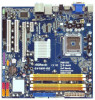
module) RoHS FSB1333 HDMI1 SPDIF_O1 30 1 IR1 USB 2.0 T: USB2 B: USB3 PWR_FAN1 IDE1 G41MH-GE USB 2.0 T: USB0 B: USB1 Top: RJ-45 Top: SIDE SPK Fan Connector (CHA_FAN1) 3 CPU Fan Connector (CPU_FAN1) 19 System Panel Header (PANEL1, Orange) 4 775-Pin CPU Socket 20 Print Port Header - ASRock G41MH-GE | User Manual - Page 12
1.5 I/O Panel 1 2 3 47 58 69 15 14 1 PS/2 Mouse Port (Green) 2 VGA/D-Sub Port * 3 LAN RJ-45 Port 4 Side Speaker (Gray) 5 Rear Speaker (Black) 6 Central / Bass (Orange) 7 Line In (Light Blue) ** 8 Front Speaker (Lime) 13 12 11 10 9 Microphone (Pink) 10 USB 2.0 Ports (USB01) 11 USB 2.0 Ports - ASRock G41MH-GE | User Manual - Page 13
cable to the front panel audio header. After restarting your computer, you will find "VIA HD Audio Deck" tool on your system. Please follow below instructions according to the OS you install. For Windows® XP / XP 64-bit OS: Please click "VIA HD Audio Deck" icon , and click "Speaker". Then you - ASRock G41MH-GE | User Manual - Page 14
settings. 1. Unplug the power cord from the wall socket before touching any component. 2. To avoid damaging the motherboard components due to static electricity, NEVER place your motherboard directly on the carpet or the like. Also remember to use a grounded wrist strap or touch a safety grounded - ASRock G41MH-GE | User Manual - Page 15
Rotate the load plate to fully open position at approximately 100 degrees. Step 2. Insert the 775-LAND CPU: Step 2-1. Hold the CPU by the edges where are marked with black lines. Step 2-2. Orient the CPU with IHS (Integrated Heat Sink) up. Locate Pin1 and the two orientation key notches. Pin1 - ASRock G41MH-GE | User Manual - Page 16
CPU is within the socket and properly mated to the orient keys. Step 3. Remove PnP Cap (Pick and Place Cap): Use your left hand index finger and thumb to support PnP cap. 2. This cap must be placed if returning the motherboard for after service. Step 4. Close the socket: Step 4-1. Rotate the load - ASRock G41MH-GE | User Manual - Page 17
(CPU_FAN1, see page 11, No. 3). For proper installation, please kindly refer to the instruction manuals of your CPU fan and heatsink. Below is an example to illustrate the installation of the heatsink for 775-LAND CPU. Step 1. Apply thermal interface material onto center of IHS on the socket surface - ASRock G41MH-GE | User Manual - Page 18
the Dual Channel Memory Technology . 4. It is not allowed to install a DDR memory module into DDR2 slot; otherwise, this motherboard and DIMM may be damaged. 5. This motherboard supports two double-sided or four single-sided DIMMs. Therefore, if you install four DDR2 DIMMs, you can only adopt four - ASRock G41MH-GE | User Manual - Page 19
matches the break on the slot. notch break notch break The DIMM only fits in one correct orientation. It will cause permanent damage to the motherboard and the DIMM if you force the DIMM into the slot at incorrect orientation. Step 3. Firmly insert the DIMM into the slot until the retaining - ASRock G41MH-GE | User Manual - Page 20
2.6 Expansion Slots (PCI and PCI Express Slots) There are 2 PCI slots and 2 PCI Express slots on this motherboard. PCI slots: PCI slots are used to install expansion cards that have the 32-bit PCI interface. PCIE slots: PCIE1 (PCIE x1 slot) is used - ASRock G41MH-GE | User Manual - Page 21
card to this motherboard. This motherboard also provides independent display controllers for DVI-D, D-Sub and HDMI to support multi VGA output VGA/DVI-D port HDMI port 2. If you have installed onboard VGA driver from our support CD to your system already, you can freely enjoy the benefits of multi - ASRock G41MH-GE | User Manual - Page 22
C. Select the display icon identified by the number 2. D. Click "Extend my Windows desktop onto this monitor". E. Right-click the display icon and select "Attached", if necessary. F. Set the "Screen Resolution" and "Color Quality" as appropriate for the second monitor. Click "Apply" or "OK" to apply - ASRock G41MH-GE | User Manual - Page 23
function is supported on this motherboard. To use HDCP function with this motherboard, you need to adopt the monitor that supports HDCP function as well. Therefore, you can enjoy the superior display quality with high-definition HDCP encryption contents. Please refer to below instruction for more - ASRock G41MH-GE | User Manual - Page 24
2.8 Jumpers Setup The illustration shows how jumpers are setup. When the jumper cap is placed on pins, the jumper is "Short". If no jumper cap is placed on pins, the jumper is "Open". The il- lustration shows a 3-pin jumper whose pin1 and pin2 are "Short" when jumper cap is placed on these 2 - ASRock G41MH-GE | User Manual - Page 25
blue end to the motherboard connect the black end to the IDE devices 80-conductor ATA 66/100 cable Note: Please refer to the instruction of your IDE Data Cable (Optional) These four Serial ATAII (SATAII) connectors support SATA data cables for internal storage devices. The current SATAII - ASRock G41MH-GE | User Manual - Page 26
2.0 headers on this motherboard. Each USB 2.0 header can support two USB 2.0 ports. This header supports an optional wireless transmitting supports Jack Sensing, but the panel wire on the chassis must support HDA to function correctly. Please follow the instruction in our manual and chassis manual - ASRock G41MH-GE | User Manual - Page 27
You don't need to connect them for AC'97 audio panel. E. Enter BIOS Setup Utility. Enter Advanced Settings, and then select Chipset Configuration. Set the Front to the ground pin. Though this motherboard provides 4-Pin CPU fan (Quiet Fan) support, the 3-Pin CPU fan still can work successfully even - ASRock G41MH-GE | User Manual - Page 28
11 No. 7) 12 24 Please connect an ATX power supply to this connector. 1 13 Though this motherboard provides 24-pin ATX power connector, 12 24 it can still work if you adopt a traditional 20-pin DDSR#1 CCTS#1 1 RRI#1 RRTS#1 GND TTXD1 DDCD#1 This COM1 header supports a serial port module. 28 - ASRock G41MH-GE | User Manual - Page 29
guide. Some default setting of SATAII hard disks may not be at SATAII mode, which operate with the best performance. In order to enable SATAII function, please follow the below instruction website for details: http://www.hitachigst.com/hdd/support/download.htm The above examples are just for your - ASRock G41MH-GE | User Manual - Page 30
Connect one end of the SATA data cable to the motherboard's SATAII connector. STEP 4: Connect the other end of the SATA data cable to the SATA / SATAII hard disk. 2.12 Driver Installation Guide To install the drivers to your system, please insert the support CD to your optical drive first. Then, the - ASRock G41MH-GE | User Manual - Page 31
BIOS FWH chip on the motherboard stores the BIOS SETUP UTILITY. You may run the BIOS SETUP UTILITY when you start up the computer. Please press or during the Power-On-Self-Test (POST) to enter the BIOS Because the BIOS software is constantly being updated, the following BIOS setup screens - ASRock G41MH-GE | User Manual - Page 32
21/2008] BIOS Version : G41MH-GE P1.00 Processor Type : Intel(R) CPU 3.20GHz (64bit) Processor Speed : 3200MHz Microcode Update : F64/4 +Tab F1 F9 F10 ESC Select Screen Select Item Change Field Select Field General Help Load Defaults Save and Exit Exit v02.54 (C) Copyright 1985-2005, - ASRock G41MH-GE | User Manual - Page 33
Setup Default (IDE/SATA) Load Power Saving Setup Default BIOS Update Utility ASRock Instant Flash Exit system setup after saving the changes. F10 key can be used for this operation. Select Screen Select Item Enter Go to Sub Screen F1 General Help F9 Load Defaults F10 Save and Exit ESC Exit - ASRock G41MH-GE | User Manual - Page 34
system to malfunction. Options for CPU CPU Configuration Chipset Configuration ACPI Configuration Storage Configuration PCIPnP Configuration Floppy Configuration SuperIO Configuration USB Configuration Select Screen Select Item Enter Go to Sub Screen F1 General Help F9 Load Defaults F10 Save - ASRock G41MH-GE | User Manual - Page 35
CPU Configuration BIOS SETUP UTILITY Advanced CPU Configuration Overclock Mode CPU Select Item Change Option General Help Load Defaults Save and Manual], [I.O.T.] and [Optimized]. The default value is [Auto]. If you select [Manual whether the ratio status of this motherboard is "Locked" or "Unlocked - ASRock G41MH-GE | User Manual - Page 36
(C1). The C1 state is supported through the native processor instructions HLT and MWAIT and requires no hardware support from the chipset. In the execute code. This option will be hidden if the current CPU does not support No-Excute Memory Protection. Hyper Threading Technology To enable this - ASRock G41MH-GE | User Manual - Page 37
General Help Load Defaults Save and Exit Exit v02.54 (C) Copyright 1985-2005, American Megatrends, Inc. DRAM Frequency If [Auto] is selected, the motherboard CPU and memory module you adopt on this motherboard. Please refer to page 8 for the CPU FSB frequency and its corresponding memory support - ASRock G41MH-GE | User Manual - Page 38
DRAM tRFC This controls the number of DRAM clocks for TRFC. Configuration options: Configuration options: [Auto], [15] to [78]. DRAM tWR This controls the number of DRAM clocks for TWR. Configuration options: Configuration options: [Auto], [3] to [15]. DRAM tWTR This controls the number of DRAM - ASRock G41MH-GE | User Manual - Page 39
DRAM RCOMP STRENGTH Configuration BIOS SETUP UTILITY Advanced DRAM RCOMP STRENGTH Settings DRAM CH0 Data) Value Min = 1 Max = 15 +F1 F9 F10 ESC Select Screen Select Item Change Option General Help Load Defaults Save and Exit Exit v02.54 (C) Copyright 1985-2005, American Megatrends, Inc. DRAM - ASRock G41MH-GE | User Manual - Page 40
DRAM CH1 G3 (Control2) This controls the number of DRAM CH1 G3 (Control2). Min: 1. Max: 15. The default value is [Auto]. DRAM CH1 G4 (Clocks1) This controls the number of DRAM CH1 G4 (Clocks1). Min: 1. Max: 15. The default value is [Auto]. DRAM CH1 G5 (Clocks2) This controls the number of DRAM CH1 - ASRock G41MH-GE | User Manual - Page 41
DRAM DLL SKEW Settings BIOS SETUP UTILITY Advanced DRAM DLL SKEW Settings DRAM CH0 CLKSET0 SKEW DRAM CH1 CLKSET0 SKEW Info:1-5-1-1-0-128 +F1 F9 F10 ESC Select Screen Select Item Change Option General Help Load Defaults Save and Exit Exit v02.54 (C) Copyright 1985-2005, American Megatrends, Inc - ASRock G41MH-GE | User Manual - Page 42
DRAM CH1 CMD SKEW This controls the number of DRAM CH1 CMD SKEW. The default value is [Auto]. DRAM CH1 CTRL0 SKEW This controls the number of DRAM CH1 CTRL0 SKEW. The default value is [Auto]. DRAM CH1 CTRL1 SKEW This controls the number of DRAM CH1 CTRL1 SKEW. The default value is [Auto]. DRAM CH1 - ASRock G41MH-GE | User Manual - Page 43
® 4 Series Express chipset family to support increased content protection and robustness requirements for motherboard through efficient memory utilization. In DVMT mode, the graphics driver feature. CPU Voltage Use this to select CPU Voltage. Configuration options: [Auto] and [Manual]. The default - ASRock G41MH-GE | User Manual - Page 44
. The default value is [Disabled]. Configuration options: [Enabled] and [Disabled]. If you want to enable this function, please set this item to [Enabled]. Besides the BIOS option, you can also choose our Intelligent Energy Saver utility to enable this function. 44 - ASRock G41MH-GE | User Manual - Page 45
Change Option General Help Load Defaults Save and Exit Exit v02.54 (C) Copyright 1985-2005, American Megatrends, Inc. Suspend to RAM Use this item to select whether to auto-detect or disable the Suspend-toRAM feature. Select [Auto] will enable this feature if the OS supports it - ASRock G41MH-GE | User Manual - Page 46
ACPI HPET Table Use this item to enable or disable ACPI HPET Table. The default value is [Disabled]. Please set this option to [Enabled] if you plan to use this motherboard to submit Windows® VistaTM certification. 46 - ASRock G41MH-GE | User Manual - Page 47
BIOS +F1 F9 F10 ESC Select Screen Select Item Change Option General Help Load Defaults Save and Exit Exit v02.54 (C) then SATAII_1, SATAII_3 will not work. Because Intel® ICH7 south bridge only supports four IDE devices under legacy OS (Windows NT), you have to choose [SATA instruction. 47 - ASRock G41MH-GE | User Manual - Page 48
Supported [Auto] [Auto] [Auto] [Auto] [Auto] [Disabled] [Enabled] Select the type of device connected to the system. +F1 F9 F10 ESC Select Screen Select Item Change Option General the hard disk information into BIOS, use a disk utility, such for a hard disk > 512 MB under DOS and Windows; for - ASRock G41MH-GE | User Manual - Page 49
maximize the IDE hard disk data transfer rate. 3.4.5 PCIPnP Configuration BIOS SETUP UTILITY Advanced Advanced PCI / PnP Settings PCI Latency Timer PCI register. +F1 F9 F10 ESC Select Screen Select Item Change Option General Help Load Defaults Save and Exit Exit v02.54 (C) Copyright 1985- - ASRock G41MH-GE | User Manual - Page 50
, you may configure the type of your floppy drive. BIOS SETUP UTILITY Advanced Floppy Configuration Floppy A [1.44 MB 312"] Select the type of floppy drive connected to the system. +F1 F9 F10 ESC Select Screen Select Item Change Option General Help Load Defaults Save and Exit Exit v02.54 - ASRock G41MH-GE | User Manual - Page 51
Parallel Port Address Use this item to set the address for the onboard parallel port or disable it. Configuration options: [Disabled], [378], and [278]. Parallel Port Mode Use this item to set the operation mode of the parallel port. The default value is [ECP+EPP]. If this option is set to [ECP+EPP - ASRock G41MH-GE | User Manual - Page 52
3.4.8 USB Configuration BIOS SETUP UTILITY Advanced USB Configuration USB Controller USB 2.0 Support Legacy USB Support [Enabled] [Enabled] [Enabled] To enable or disable the onboard USB controllers. +F1 F9 F10 ESC Select Screen Select Item Change Option General Help Load Defaults Save and - ASRock G41MH-GE | User Manual - Page 53
you to monitor the status of the hardware on your system, including the parameters of the CPU temperature, motherboard temperature, CPU fan speed, chassis fan speed, and the critical voltage. BIOS SETUP UTILITY Main Smart Advanced H/W Monitor Boot Security Exit Hardware Health Event Monitoring - ASRock G41MH-GE | User Manual - Page 54
for you to configure the boot settings and the boot priority. BIOS SETUP UTILITY Main Smart Advanced H/W Monitor Boot Security Exit Boot of POST messages. +F1 F9 F10 ESC Select Screen Select Item Change Option General Help Load Defaults Save and Exit Exit v02.54 (C) Copyright 1985-2003, - ASRock G41MH-GE | User Manual - Page 55
Logo". Configuration options: [Auto], [EuP], [Scenery] and [ASRock]. The default value is [Auto]. Currently, the option [Auto] password, you may also clear it. BIOS SETUP UTILITY Main Smart Advanced H/W Monitor Select Screen Select Item Enter Change F1 General Help F9 Load Defaults F10 Save and - ASRock G41MH-GE | User Manual - Page 56
used for this operation. Select Screen Select Item Enter Go to Sub Screen F1 General Help F9 Load Defaults F10 Save and Exit ESC Exit v02.54 (C) Copyright and exit setup?" Select [OK] to save the changes and exit the BIOS SETUP UTILITY. Discard Changes and Exit When you select this option, it will - ASRock G41MH-GE | User Manual - Page 57
in this chapter for general reference only. Refer to your OS documentation for more information. 4.2 Support CD Information The Support CD that came with the motherboard contains necessary drivers and useful utilities that enhance the motherboard features. 4.2.1 Running The Support CD To begin using
-
 1
1 -
 2
2 -
 3
3 -
 4
4 -
 5
5 -
 6
6 -
 7
7 -
8
-
9
-
10
-
11
-
12
-
13
-
14
-
15
-
16
-
17
-
18
-
19
-
20
-
21
-
22
-
23
-
24
-
25
-
26
-
27
-
28
-
29
-
30
-
31
-
32
-
33
-
34
-
35
-
36
-
37
-
38
-
39
-
40
-
41
-
42
-
43
-
44
-
45
-
46
-
47
-
48
-
49
-
50
-
51
-
52
-
53
-
54
-
55
-
56
-
57
 |
 |

1
G41MH-GE
User Manual
Version 1.0
Published September 2009
Copyright©2009 ASRock INC. All rights reserved.