ASRock G41MH-LE3 User Manual
ASRock G41MH-LE3 Manual
 |
View all ASRock G41MH-LE3 manuals
Add to My Manuals
Save this manual to your list of manuals |
ASRock G41MH-LE3 manual content summary:
- ASRock G41MH-LE3 | User Manual - Page 1
G41MH-LE3 User Manual Version 1.0 Published May 2010 Copyright©2010 ASRock INC. All rights reserved. 1 - ASRock G41MH-LE3 | User Manual - Page 2
any form or by any means, except duplication of documentation by the purchaser for backup purpose, without written consent of ASRock Inc. Products and corporate names appearing in this manual may or may not be registered trademarks or copyrights of their respective companies, and are used only for - ASRock G41MH-LE3 | User Manual - Page 3
Contents 1 Introduction 5 1.1 Package Contents 5 1.2 Specifications 6 1.3 2.12 Driver Installation Guide 28 2.13 Untied Overclocking Technology 28 3 BIOS SETUP UTILITY 29 3.1 Introduction 29 3.1.1 BIOS Menu 3.4.7 Super IO Configuration 47 3.4.8 USB Configuration 49 3.5 Hardware Health Event - ASRock G41MH-LE3 | User Manual - Page 4
3.7 Security Screen 52 3.8 Exit Screen 53 4 Software Support 54 4.1 Install Operating System 54 4.2 Support CD Information 54 4.2.1 Running Support CD 54 4.2.2 Drivers Menu 54 4.2.3 Utilities Menu 54 4.2.4 Contact Information 54 4 - ASRock G41MH-LE3 | User Manual - Page 5
information about the model you are using. www.asrock.com/support/index.asp 1.1 Package Contents ASRock G41MH-LE3 Motherboard (Micro ATX Form Factor: 9.6-in x 8.4-in, 24.4 cm x 21.3 cm) ASRock G41MH-LE3 Quick Installation Guide ASRock G41MH-LE3 Support CD Two Serial ATA (SATA) Data Cables (Optional - ASRock G41MH-LE3 | User Manual - Page 6
options: D-Sub, DVI-D and HDMI - Supports HDMI Technology with max. resolution up to 1920x1200 (1080P) - Supports DVI with max. resolution up to 1920x1200 @ 75Hz - Supports D-Sub with max. resolution up to 2048x1536 @ 60Hz - Supports HDCP function with DVI and HDMI ports - Supports Full HD 1080p Blu - ASRock G41MH-LE3 | User Manual - Page 7
(support 4 USB 2.0 ports) - 8Mb AMI BIOS - AMI Legal BIOS - Supports "Plug and Play" - ACPI 1.1 Compliance Wake Up Events - Supports jumperfree - AMBIOS 2.3.1 Support - Supports I. O. T. (Intelligent Overclocking Technology) - Drivers, Utilities, AntiVirus Software (Trial Version), ASRock Software - ASRock G41MH-LE3 | User Manual - Page 8
please visit our website: http://www.asrock.com WARNING Please realize that there is a certain the setting in the BIOS, applying Untied Overclocking Technology supports Dual Channel Memory Technology. Before you implement Dual Channel Memory Technology, make sure to read the installation guide - ASRock G41MH-LE3 | User Manual - Page 9
to SATAII connector, please read the "SATAII Hard Disk Setup Guide" on page 27 to adjust your SATAII hard disk drive to BIOS setup menu to access ASRock Instant Flash. Just launch this tool and save the new BIOS file to your USB flash drive, floppy disk or hard drive, then you can update your BIOS - ASRock G41MH-LE3 | User Manual - Page 10
14. EuP, stands for Energy Using Product, was a provision regulated by European Union to define the power consumption for the completed system. According to EuP, the total AC power of the completed system shall be under 1.00W in off mode condition. To meet EuP standard, an EuP ready motherboard and - ASRock G41MH-LE3 | User Manual - Page 11
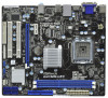
HDMI1 24.4cm (9.6 in) G41MH-LE3 32 31 30 USB 2.0 T: USB0 B: USB1 Top: RJ-45 USB 2.0 T: USB2 LAN PHY B: USB3 PWR_FAN1 Intel G41 Chipset TPM1 1 7 CHA_FAN1 8 IDE1 Connector (IDE1, Blue) 26 PCI Slots (PCI1- 2) 10 BIOS SPI Chip 27 PCI Express x16 Slot (PCIE2) 11 South Bridge Controller - ASRock G41MH-LE3 | User Manual - Page 12
1 PS/2 Mouse Port (Green) 2 VGA/D-Sub Port * 3 LAN RJ-45 Port 4 Line In (Light Blue) ** 5 Front Speaker (Lime) 6 Microphone (Pink) 7 USB 2.0 Ports (USB23) 8 USB 2.0 Ports (USB01) 9 HDMI Port 10 VGA/DVI-D Port 11 PS/2 Keyboard Port (Purple) * There are two LED next to the LAN port. Please refer to - ASRock G41MH-LE3 | User Manual - Page 13
Chapter 2: Installation This is a Micro ATX form factor (9.6" x 8.4", 24.4 x 21.3 cm) motherboard. Before you install the motherboard, study the configuration of your chassis to ensure that the motherboard fits into it. Make sure to unplug the power cord before installing or removing the motherboard - ASRock G41MH-LE3 | User Manual - Page 14
2.3 CPU Installation For the installation of Intel 775-LAND CPU, please follow the steps below. 775-Pin Socket Overview Before you insert the 775-LAND CPU into the socket, please check if the CPU surface is unclean or if there is any bent pin on the socket. Do not force to insert the CPU into the - ASRock G41MH-LE3 | User Manual - Page 15
Pick and Place Cap): Use your left hand index finger and thumb to support the load plate edge, engage PnP cap with right hand thumb and peel the PnP cap. 2. This cap must be placed if returning the motherboard for after service. Step 4. Close the socket: Step 4-1. Rotate the load plate onto the IHS. - ASRock G41MH-LE3 | User Manual - Page 16
Heatsink This motherboard is equipped with 775-Pin socket that supports Intel 775-LAND CPU. Please adopt the type of , see page 11, No. 33). For proper installation, please kindly refer to the instruction manuals of your CPU fan and heatsink. Below is an example to illustrate the installation of - ASRock G41MH-LE3 | User Manual - Page 17
2.5 Installation of Memory Modules (DIMM) G41MH-LE3 motherboard provides two 240-pin DDR3 (Double Data Rate 3) DIMM slots, and supports Dual Channel Memory Technology. For dual channel configuration, you always need to install two identical (the same brand, speed, size and chip-type) memory modules - ASRock G41MH-LE3 | User Manual - Page 18
install the add-on PCI Express VGA card or other PCIE device to PCIE2 (PCIE x16 slot), only D-Sub port will be enabled. DVI-D and HDMI ports will not work. Installing an expansion card Step 1. Before installing the expansion card, please make sure that the power supply is switched off or - ASRock G41MH-LE3 | User Manual - Page 19
, connect D-Sub monitor cable to VGA/D-Sub port on the I/O panel, or connect HDMI monitor cable to HDMI port on the I/O panel. VGA/D-Sub port VGA/DVI-D port HDMI port 2. If you have installed onboard VGA driver from our support CD to your system already, you can freely enjoy the benefits of dual - ASRock G41MH-LE3 | User Manual - Page 20
3. Set up a dual-monitor display. For Windows® XP / XP 64-bit OS: Right click the desktop, choose "Properties", and select the "Settings" tab so that you can adjust the parameters of the dual-monitor according to the steps below. A. Click the "Identify" button to display a large number on each - ASRock G41MH-LE3 | User Manual - Page 21
function with this motherboard, you need to adopt the monitor that supports HDCP function as well. Therefore, you can enjoy the superior display quality with high-definition HDCP encryption contents. Please refer to below instruction for more details about HDCP function. What is HDCP? HDCP stands - ASRock G41MH-LE3 | User Manual - Page 22
wake +5V +5V_DUAL up events. Note: To select +5V_DUAL, it requires 2 Amp and higher standby current provided by power supply. When you select +5V_DUAL, USB devices can wake up the system under S3 (Suspend to RAM) state. USB_PWR3 1_2 (see p.11, No. 19) 2_3 Short pin2, pin3 to enable +5VSB - ASRock G41MH-LE3 | User Manual - Page 23
devices 80-conductor ATA 66/100 cable Note: Please refer to the instruction of your IDE device vendor for the details. Serial ATAII Connectors (SATAII_1 p.11, No. 14) These four Serial ATAII (SATAII) connectors support SATA data cables for internal storage devices. The current SATAII interface - ASRock G41MH-LE3 | User Manual - Page 24
GND P+4 P-4 USB_PWR IRTX +5V DUMMY 1 GND IRRX Besides three default USB 2.0 ports on the I/O panel, there are two USB 2.0 headers on this motherboard. Each USB 2.0 header can support two USB 2.0 ports. This header supports an optional wireless transmitting and receiving infrared module. Print Port - ASRock G41MH-LE3 | User Manual - Page 25
allows convenient connection and control of audio devices. 1. High Definition Audio supports Jack Sensing, but the panel wire on the chassis must support HDA to function correctly. Please follow the instruction in our manual and chassis manual to install your system. 2. If you use AC'97 audio panel - ASRock G41MH-LE3 | User Manual - Page 26
Though this motherboard provides 4-Pin CPU fan (Quiet Fan) support, the 3-Pin CPU fan still can work successfully even without the fan speed control function. If supply to this connector. RRXD1 DDTR#1 DDSR#1 CCTS#1 1 RRI#1 RRTS#1 GND TTXD1 DDCD#1 This COM1 header supports a serial port module. 26 - ASRock G41MH-LE3 | User Manual - Page 27
guide. Some default setting of SATAII hard disks may not be at SATAII mode, which operate with the best performance. In order to enable SATAII function, please follow the below instruction remove the jumpers from pin 5 and pin 6. SAMSUNG 7531 8642 If pin 3 and pin 4 .com/hdd/support/download.htm The - ASRock G41MH-LE3 | User Manual - Page 28
. STEP 4: Connect the other end of the SATA data cable to the SATA / SATAII hard disk. 2.12 Driver Installation Guide To install the drivers to your system, please insert the support CD to your optical drive first. Then, the drivers compatible to your system can be auto-detected and listed on the - ASRock G41MH-LE3 | User Manual - Page 29
default system device to locate and load the Operating System Security To set up the security features Exit To exit the current screen or the BIOS SETUP UTILITY Use < > key or < > key to choose among the selections on the menu bar, and then press to get into the sub screen - ASRock G41MH-LE3 | User Manual - Page 30
Main OC Tweaker Advanced H/W Monitor Boot Security Exit System Overview System Time System Date [14:00:09] [Thu 05/13/2010] BIOS Version : G41MH-LE3 P1.00 Processor Type : Intel (R) Pentium (R) Dual CPU E2220 @ 2.40GHz (64bit) Processor Speed : 2400MHz Microcode Update : 6FB/A3 Cache Size - ASRock G41MH-LE3 | User Manual - Page 31
the OC Tweaker screen, you can set up overclocking features. BIOS SETUP UTILITY Main OC Tweaker Advanced H/W Monitor Boot Security Exit refer to page 8 for the CPU FSB frequency and its corresponding memory support frequency. DRAM Command Rate Use this item to adjust DRAM Command Rate. Configurationoptions: [1N - ASRock G41MH-LE3 | User Manual - Page 32
DRAM Timing Configuration BIOS SETUP UTILITY OC Tweaker DRAM Timing Control DRAM tCL 6 DRAM tRCD 6 DRAM tRP 6 DRAM tRAS 15 DRAM tRFC 44 DRAM tWR 6 DRAM tWTR 4 DRAM tRRD 3 - ASRock G41MH-LE3 | User Manual - Page 33
allow you changing the ratio value of this motherboard. If the CPU you adopt supports EIST (Intel (R) SpeedStep(tm) tech.), and you plan to adjust the ratio options: [Auto], [Manual], [I.O.T.] and [Optimized]. The default value is [Auto]. If you select [Manual], Untied Overclocking function is - ASRock G41MH-LE3 | User Manual - Page 34
DRAM Voltage Use this to select DRAM Voltage. Configuration options: [Auto], [1.300V] to [2.050V]. The default value of this feature is [Auto]. NB Voltage Use this to select NB Voltage. Configuration options: [Auto], [1.046V] to [1.493V]. The default value of this feature is [Auto]. SB Voltage Use - ASRock G41MH-LE3 | User Manual - Page 35
to malfunction. CPU Configuration Chipset Configuration ACPI Configuration Storage Configuration PCIPnP Configuration Floppy Configuration SuperIO Configuration USB Configuration BIOS Update Utility ASRock Instant Flash Select Screen Select Item Enter Go to Sub Screen F1 General Help F9 Load - ASRock G41MH-LE3 | User Manual - Page 36
3.4.1 CPU Configuration BIOS SETUP UTILITY Advanced CPU Configuration Overclock Mode CPU Mode. Configuration options: [Auto], [Manual], [I.O.T.] and [Optimized]. The default value is [Auto]. If you select [Manual], Untied Overclocking function is enabled. Please the CPU you adopt supports 36 - ASRock G41MH-LE3 | User Manual - Page 37
option " Intel (R) SpeedStep(tm) tech." in advance. Enhance Halt State All processors support the Halt State (C1). The C1 state is supported through the native processor instructions HLT and MWAIT and requires no hardware support from the chipset. In the C1 power state, the processor maintains the - ASRock G41MH-LE3 | User Manual - Page 38
Option General Help Load Defaults Save and Exit Exit v02.54 (C) Copyright 1985-2005, American Megatrends, Inc. DRAM RCOMP and tRD Configuration BIOS SETUP UTILITY Advanced DRAM RCOMP STRENGTH Settings DRAM CH0 RCOMP STRENGTH Info : 54-0-11-6-6-6-6 DRAM CH0 RCOMP ODT DRAM CH0 G0 (Data) DRAM - ASRock G41MH-LE3 | User Manual - Page 39
DRAM CH0 G3 (Control2) This controls the number of DRAM CH0 G3 (Control2). Min: 1. Max: 15. The default value is [Auto]. DRAM CH0 G4 (Clocks1) This controls the number of DRAM CH0 G4 (Clocks1). Min: 1. Max: 15. The default value is [Auto]. DRAM CH0 G5 (Clocks2) This controls the number of DRAM CH0 - ASRock G41MH-LE3 | User Manual - Page 40
DRAM DLL SKEW Configuration BIOS SETUP UTILITY Advanced DRAM DLL SKEW Settings DRAM CH0 CLKSET0 SKEW Info:0-0-0-0-0-0 DRAM CH0 CLKSET0 SKEW [Auto] DRAM CH0 CLKSET1 SKEW Info:0-0-0-0-0-0 DRAM CH0 CLKSET1 - ASRock G41MH-LE3 | User Manual - Page 41
enable this function, please set this item to [Enabled]. Besides the BIOS option, you can also choose our Intelligent Energy Saver utility to graphics feature in Intel® 4 Series Express chipset family to support increased content protection and robustness requirements for premium content playback ( - ASRock G41MH-LE3 | User Manual - Page 42
and is cooperatively using this memory with other system components. This item will not be used under Windows® VistaTM OS because the driver will intelligently detect physical memory available and allocate necessary video memory. DVMT/FIXED Memory You are allowed to adjust the shared memory size - ASRock G41MH-LE3 | User Manual - Page 43
3.4.3 ACPI Configuration BIOS SETUP UTILITY Advanced ACPI Configuration Suspend To RAM Restore on auto-detect or disable the Suspend-toRAM feature. Select [Auto] will enable this feature if the OS supports it. Check Ready Bit Use this item to enable or disable the feature Check Ready Bit. Restore - ASRock G41MH-LE3 | User Manual - Page 44
3.4.4 Storage Configuration BIOS SETUP UTILITY Advanced Storage Configuration ATA/IDE [PATA Only], then all SATAII will not work, only IDE will work. Because Intel® ICH7 south bridge only supports four IDE devices under legacy OS (Windows NT), you have to choose [SATA 1, SATA 2, SATA 3, SATA - ASRock G41MH-LE3 | User Manual - Page 45
the "Primary IDE Master" as the example in the following instruction. BIOS SETUP UTILITY Advanced Primary IDE Master Device Vendor Size LBA Mode 32Bit Data Transfer :Hard Disk :ST340014A :40.0 GB :Supported :16Sectors :4 :MultiWord DMA-2 :Ultra DMA-5 :Supported [Auto] [Auto] [Auto] [Auto] [Auto] - ASRock G41MH-LE3 | User Manual - Page 46
], [Enabled]. 32-Bit Data Transfer Use this item to enable 32-bit access to maximize the IDE hard disk data transfer rate. 3.4.5 PCIPnP Configuration BIOS SETUP UTILITY Advanced Advanced PCI / PnP Settings PCI Latency Timer PCI IDE BusMaster [32] [Enabled] Value in units of PCI clocks for PCI - ASRock G41MH-LE3 | User Manual - Page 47
Address Parallel Port Mode EPP Version ECP Mode DMA Channel Parallel Port IRQ [Enabled] [3F8 / IRQ4] [Disabled] [378] [ECP + EPP] [1.9] [DMA3] [IRQ7] Allow BIOS to Enable or Disable Floppy Controller. +F1 F9 F10 ESC Select Screen Select Item Change Option General Help Load Defaults Save and Exit - ASRock G41MH-LE3 | User Manual - Page 48
Parallel Port Address Use this item to set the address for the onboard parallel port or disable it. Configuration options: [Disabled], [378], and [278]. Parallel Port Mode Use this item to set the operation mode of the parallel port. The default value is [ECP+EPP]. If this option is set to [ECP+EPP - ASRock G41MH-LE3 | User Manual - Page 49
or disable the use of USB controller. USB 2.0 Support Use this item to enable or disable the USB 2.0 support. Legacy USB Support Use this option to select legacy support for USB devices. There are four configuration options: [Enabled], [Auto], [Disabled] and [BIOS Setup Only]. The default value - ASRock G41MH-LE3 | User Manual - Page 50
system, including the parameters of the CPU temperature, motherboard temperature, CPU fan speed, chassis fan speed, and the critical voltage. BIOS SETUP UTILITY Main OC Tweaker Advanced H/W Monitor Boot Security Exit Hardware Health Event Monitoring CPU Temperature M / B Temperature CPU Fan Speed - ASRock G41MH-LE3 | User Manual - Page 51
v02.54 (C) Copyright 1985-2005, American Megatrends, Inc. 3.6.1 Boot Settings Configuration BIOS SETUP UTILITY Boot Boot Settings Configuration Full Screen Logo AddOn ROM Display Boot Logo Boot Logo". Configuration options: [Auto], [EuP], [Scenery] and [ASRock]. The default value is [Auto]. 51 - ASRock G41MH-LE3 | User Manual - Page 52
this section, you may set or change the supervisor/user password for the system. For the user password, you may also clear it. BIOS SETUP UTILITY Main OC Tweaker Advanced H/W Monitor Boot Security Exit Security Settings Supervisor Password : Not Installed User Password : Not Installed Change - ASRock G41MH-LE3 | User Manual - Page 53
. Discard Changes When you select this option, it will pop-out the following message, "Discard changes?" Select [OK] to discard all changes. Load BIOS Defaults Load BIOS default values for all the setup questions. F9 key can be used for this operation. Load Performance Setup Default (IDE/SATA) This - ASRock G41MH-LE3 | User Manual - Page 54
install the necessary drivers to activate the devices. 4.2.3 Utilities Menu The Utilities Menu shows the applications software that the motherboard supports. Click on a specific item then follow the installation wizard to install it. 4.2.4 Contact Information If you need to contact ASRock or want to
-
 1
1 -
 2
2 -
 3
3 -
 4
4 -
 5
5 -
 6
6 -
 7
7 -
8
-
9
-
10
-
11
-
12
-
13
-
14
-
15
-
16
-
17
-
18
-
19
-
20
-
21
-
22
-
23
-
24
-
25
-
26
-
27
-
28
-
29
-
30
-
31
-
32
-
33
-
34
-
35
-
36
-
37
-
38
-
39
-
40
-
41
-
42
-
43
-
44
-
45
-
46
-
47
-
48
-
49
-
50
-
51
-
52
-
53
-
54
 |
 |

1
G41MH-LE3
User Manual
Version 1.0
Published May 2010
Copyright©2010 ASRock INC. All rights reserved.