ASRock GE PRO-M User Manual
ASRock GE PRO-M Manual
 |
View all ASRock GE PRO-M manuals
Add to My Manuals
Save this manual to your list of manuals |
ASRock GE PRO-M manual content summary:
- ASRock GE PRO-M | User Manual - Page 1
GE Pro-M / GE Pro-HT User Manual Version 1.0 Published December 2002 Copyright©2002 ASRock INC. All rights reserved. 1 - ASRock GE PRO-M | User Manual - Page 2
any form or by any means, except duplication of documentation by the purchaser for backup purpose, without written consent of ASRock Inc. Products and corporate names appearing in this manual may or may not be registered trademarks or copyrights of their respective companies, and are used only for - ASRock GE PRO-M | User Manual - Page 3
Package Contents 4 1.2 Specifications 4 1.3 Motherboard Layout (GE Pro-M 6 1.4 Motherboard Layout (GE Pro-HT 7 1.5 ASRock I/OTM (GE Pro-M / GE Pro-HT 8 2 Installation 9 2.1 Screw Holes 9 2.2 Pre-installation Precautions 9 2.3 CPU Installation 9 2.4 Installation of Heatsink and CPU fan 10 - ASRock GE PRO-M | User Manual - Page 4
Pro-M / GE Pro-HT Quick Installation Guide ASRock Intel-SiS Support CD 1 cable for IDE devices (1 x ATA 66/100/133) 1 cable for floppy drive (1 x ribbon cable) 1 ASRock I/O shield 1 COM port bracket 1.2 Specifications Platform: Micro ATX form factor (9.6" x 9.6", 24.4 x 24.4 cm) CPU: Socket 478 - ASRock GE PRO-M | User Manual - Page 5
Microsoft® Windows® 98/ME/2000. Please refer to Microsoft® official document at http://www.microsoft.com/HWDEV/BUS/usb/USB2support.asp 4. Although GE Pro-M/GE Pro-HT offers stepless control, it is not recommended to perform over clocking. Frequencies other than the recommended CPU bus frequency - ASRock GE PRO-M | User Manual - Page 6
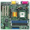
PCI 2 11 2MB PCI 3 BIOS AMR1 GE Pro-M 26 18 8 7 01 23 01 23 SiS South Bridge CMOS 9 Battery CHA_FAN1 CLRCMOS1 FLOPPY1 IR1 COM1 USB45 SPEAKER1 RESET HDLED PANEL1 PWRBTN PLED 10 14 15 12 16 25 17 13 1 ATX power connector (ATXPWR1) 2 CPU socket 3 CPU fan connector (CPU_FAN1 - ASRock GE PRO-M | User Manual - Page 7
1.4 Motherboard Layout (GE Pro-HT) 22 3 21 BIOS AMR1 GE Pro-HT 26 18 8 7 01 23 01 23 SiS South Bridge CMOS 9 Battery CHA_FAN1 CLRCMOS1 FLOPPY1 IR1 COM1 USB45 SPEAKER1 RESET HDLED PANEL1 PWRBTN PLED 10 14 15 12 16 25 17 13 1 ATX power connector (ATXPWR1) 2 CPU socket 3 CPU - ASRock GE PRO-M | User Manual - Page 8
1.5 ASRock I/OTM (GE Pro-M / GE Pro-HT) 1 Parallel port 2 RJ-45 port 3 Game port 4 Microphone (Pink) 5 Line In (Light Blue) 6 Line Out (Lime) 7 USB 2.0 ports 8 VGA port 9 PS/2 keyboard port (Purple) 10 PS/2 mouse port (Green) 8 - ASRock GE PRO-M | User Manual - Page 9
GE Pro-M / GE Pro-HT is a Micro ATX form factor (9.6" x 9.6", 24.4 x 24.4 cm) motherboard. Before you install the motherboard, study the configuration of your chassis to ensure that the motherboard fits into it. Make sure to unplug the power cord before installing or removing the motherboard - ASRock GE PRO-M | User Manual - Page 10
CPU into the socket to avoid bending of the pins. Step 4. When the CPU is in place, press it firmly on the socket while you push down the socket lever to secure the CPU proper installation, please kindly refer to the instruction manuals of vendors of CPU fan and heatsink. 2.5 Installation of Memory - ASRock GE PRO-M | User Manual - Page 11
) There are 3 PCI slots, 1 AMR slot, and 1 AGP slot on both GE Pro-M and GE Pro-HT motherboards. PCI slots: PCI slots are used to install expansion cards that have the 32-bit PCI interface. AMR slot: AMR slot is used to insert ASRock MR card with v.92 Modem functionality. AGP slot: The AGP slot is - ASRock GE PRO-M | User Manual - Page 12
2.7 Jumpers Setup The illustration shows how jumpers are setup. When the jumper cap is placed on pins, the jumper is "SHORT". If no jumper cap is placed on pins, the jumper is "OPEN". The illustration shows a 3-pin jumper whose pin1 and pin2 are "SHORT" when jumper cap is placed on these 2 pins. - ASRock GE PRO-M | User Manual - Page 13
PIN1 IDE1 Blue Connect to the motherboard PIN1 IDE2 Black Connect to the P+4 P-4USB_PWR 1 USB_PWR P-5 P+5 GND DUMMY ASRock I/OTM already provided 4 default USB ports. supports an optional wireless transmitting and receiving infrared module. These connectors allow you to receive stereo audio - ASRock GE PRO-M | User Manual - Page 14
(4-pin SPEAKER 1) (see p.6/p.7 item 15) Chassis fan connector (3-pin CHA_FAN1) (see p.6/p.7 item 9) CPU fan connector (3-pin CPU_FAN1) (see p.6/p.7 item 3) ATX power connector (20-pin ATXPWR1) (see p.6/p.7 an ATX power supply to the connector. This connector supports a serial port module. 14 - ASRock GE PRO-M | User Manual - Page 15
BIOS Setup Utility. The Flash Memory on the motherboard stores the BIOS Setup Utility. When you start up the computer, there is a chance for you to run the BIOS the predetermined choices. Because the BIOS software is constantly being updated, the following BIOS setup screens and descriptions are for - ASRock GE PRO-M | User Manual - Page 16
Processor Speed Cache Size Microcode Update Total Memory DDR1 DDR2 SDR1 SDR2 AMIBIOS SETUP UTILITY - VERSION 3.31a Security Power Boot Exit Dec 18 2002 Tue 20:07:40 [ Setup Help ] Month: Jan - Dec Day: 01 - 31 Year: 1980 - 2099 GE Pro-HT BIOS P1.00 Pentium (R) 4 Family CPU 2100 MHz 512 KB F23 - ASRock GE PRO-M | User Manual - Page 17
may due to that the hard disk is too old or too new. If the hard disk was already formatted on an older system, the BIOS Setup may detect incorrect parameters. In these cases, select [User] to manually enter the IDE hard disk drive parameters. After entering the hard disk information into - ASRock GE PRO-M | User Manual - Page 18
Maximum Capacity This field shows the drive's maximum capacity as calculated by the BIOS based on the drive information you entered. LBA Mode This allows user to select the LBA mode for a hard disk > 512 MB under DOS and Windows; for Netware and UNIX user, select [Off] to disable the LBA mode. - ASRock GE PRO-M | User Manual - Page 19
detects installed devices. Install the necessary drivers to activate the devices. 4.2.3 Utilities Menu The Utilities Menu shows the applications software that the motherboard supports. Click on a specific item then follow the installation wizard to install it. 4.2.4 ASRock PC-DIY Live Demo Program - ASRock GE PRO-M | User Manual - Page 20
Frequency: If [Auto] is selected, the motherboard detects the memory module(s) inserted and automatically assigns appropriate frequency. You can also select other value as operating frequency: [200MHz], [266MHz], [333MHz]. Hyper-Threading Technology (for GE Pro-HT only): To enable this feature, it - ASRock GE PRO-M | User Manual - Page 21
AMIBIOS SETUP UTILITY - VERSION 3.31a Chipset Configuration [ Setup Help ] AGP Aperture Size Onboard VGA Share Memory USB Controller USB Device Legacy Support 32MB 4MB Disabled Disabled to select the size of mapped memory for graphics data. F1:Help Esc:Previous Menu :Select Item - ASRock GE PRO-M | User Manual - Page 22
disable onboard AC'97 audio feature. OnBoard MC'97 Modem: Enable or disable onboard MC'97 modem feature. System Hardware Monitor: You can check the status of the hardware on your system. It allows you to monitor the parameters for CPU temperature, Motherboard temperature, CPU fan speed, and critical - ASRock GE PRO-M | User Manual - Page 23
Advanced AMIBIOS SETUP UTILITY - VERSION 3.31a System Hardware Monitor [ Setup Help ] CPU Temperature M/B Temperature CPU Fan Speed Chassis Fan Speed Vcore + 3.30V + 5.00V +12.00V 35 C / 95 F 27 C / 82 F 3110 RPM 0 RPM 1.728 V 3.312 V 4.975 V 12.167 V F1:Help Esc: - ASRock GE PRO-M | User Manual - Page 24
is performed before BIOS setup. If [Always] option is selected, the "Password Check" is performed before both boot-up and BIOS setup. 3. supports it. Repost Video on S3 Resume: This feature allows you to repost video on S3 resume. It is recommended to enable this feature under Microsoft® Windows® - ASRock GE PRO-M | User Manual - Page 25
the sub-menu, the message "Save current settings and exit" will appear. If you press , it will save the current settings and exit the BIOS SETUP Utility. 25 - ASRock GE PRO-M | User Manual - Page 26
Discarding Changes: After you enter the submenu, the message "Quit without saving changes" will appear. If you press , you will exit the BIOS Setup Utility without making any changes to the settings. Load Default Settings: After you enter the submenu, the message "Load Default Settings" will
-
 1
1 -
 2
2 -
 3
3 -
 4
4 -
 5
5 -
 6
6 -
 7
7 -
8
-
9
-
10
-
11
-
12
-
13
-
14
-
15
-
16
-
17
-
18
-
19
-
20
-
21
-
22
-
23
-
24
-
25
-
26
 |
 |

1
GE Pro-M / GE Pro-HT
User Manual
Version 1.0
Published December 2002
Copyright©2002 ASRock INC. All rights reserved.