ASRock H310M-STX User Manual
ASRock H310M-STX Manual
 |
View all ASRock H310M-STX manuals
Add to My Manuals
Save this manual to your list of manuals |
ASRock H310M-STX manual content summary:
- ASRock H310M-STX | User Manual - Page 1
- ASRock H310M-STX | User Manual - Page 2
interference received, including interference that may cause undesired operation. CALIFORNIA, USA ONLY The Lithium battery adopted on this motherboard contains Perchlorate, a toxic substance controlled in Perchlorate Best Management Practices (BMP) regulations passed by the California Legislature - ASRock H310M-STX | User Manual - Page 3
AUSTRALIA ONLY Our goods come with guarantees that cannot be excluded under the Australian Consumer Law. You are entitled to a replacement or refund for a major failure and compensation for any other reasonably foreseeable loss or damage caused by our goods. You are also entitled to have the goods - ASRock H310M-STX | User Manual - Page 4
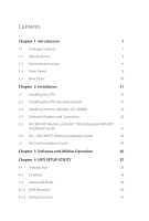
1 Introduction 1 1.1 Package Contents 1 1.2 Specifications 2 1.3 Motherboard Layout 6 1.4 Front Panel 9 1.5 Rear Panel 10 Chapter (Integrated WiFi/BT) Installation Guide 21 2.6 M.2_SSD (NGFF) Module Installation Guide 23 2.7 SD Card Installation Guide 25 Chapter 3 Software and - ASRock H310M-STX | User Manual - Page 5
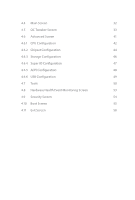
4.4 Main Screen 32 4.5 OC Tweaker Screen 33 4.6 Advanced Screen 41 4.6.1 CPU Configuration 42 4.6.2 Chipset Configuration 44 4.6.3 Storage Configuration 46 4.6.4 Super IO Configuration 47 4.6.5 ACPI Configuration 48 4.6.6 USB Configuration 49 4.7 Tools 50 4.8 Hardware Health - ASRock H310M-STX | User Manual - Page 6
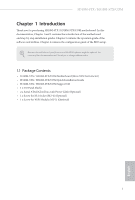
and the BIOS software might be updated, the content of this documentation will be subject to change without notice. 1.1 Package Contents • H310M-STX / H310M-STX/COM Motherboard (Mini-STX Form Factor) • H310M-STX / H310M-STX/COM Quick Installation Guide • H310M-STX / H310M-STX/COM Support CD - ASRock H310M-STX | User Manual - Page 7
• Mini-STX Form Factor CPU Chipset • Supports 9th and 8th Gen Intel® CoreTM Processors (Socket 1151) • Supports CPU up to 65W • 5 Power Phase design • Supports Intel® Turbo Boost 2.0 Technology • Intel® H310 Memory • Dual Channel DDR4 Memory Technology • 2 x DDR4 SO-DIMM Slots • Supports DDR4 - ASRock H310M-STX | User Manual - Page 8
H310M-STX / H310M-STX/COM Audio LAN Front Panel I/O • Max. shared memory 1024MB * The size of maximum shared memory may vary from different operating systems. • Three graphics output options: D-Sub, HDMI and DisplayPort 1.2 * Supports up to 2 displays simultaneously • Supports HDMI with max. - ASRock H310M-STX | User Manual - Page 9
COM Port Header (for H310M-STX/COM only) • 1 x Chassis Intrusion Header • 2 x CPU Fan Connectors (2 x 4-pin) • 1 x MONO Speaker Header • 1 x Front Panel Header • 1 x USB 2.0 Header (Supports 2 USB 2.0 ports) (Supports ESD Protection) • 1 x SD Card Socket • 1 x Audio Header BIOS Feature • AMI UEFI - ASRock H310M-STX | User Manual - Page 10
and devices of your system. It should be done at your own risk and expense. We are not responsible for possible damage caused by overclocking. Mini-STX Chassis Support List Vendor SilverStone Technology Inc. AKasa Model VT01S A-STX04-A1B / A-STX04-M1B English 5 - ASRock H310M-STX | User Manual - Page 11
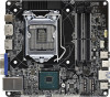
1.3 Motherboard Layout 1 23 RoHS DC Jack CPU_FAN2 CPU_FAN1 DP1 DDR4_A1 DDR4_B1 HDMI1 Audio CODEC VGA1 T: USB 2.0 USB3 B: USB 3.1 Gen1 USB4 Top: RJ-45 9 1 CI1 SPEAKER1 1 4 USB_5_6 5 1 COM1 Mic In 1 6 USB 3.1 Gen1 USB_2 Intel Chipset M2_1_CT1 BIOS ROM M2_2_CT1 Super I/O PANEL1 PLED - ASRock H310M-STX | User Manual - Page 12
Back Side View H310M-STX / H310M-STX/COM CMOS Battery SATA3 SATA3 10 11 12 13 7 English - ASRock H310M-STX | User Manual - Page 13
Slots (DDR4_A1, DDR4_B1) 3 CPU Fan Connector (CPU_FAN1) 4 MONO Speaker Header (SPEAKER1) 5 USB 2.0 Header (USB_5_6) 6 COM Port Header (COM1) (for H310M-STX/COM only) 7 System Panel Header (PANEL1) 8 Audio Header (AUDIO3) 9 Chassis Intrusion Header (CI1) 10 SATA3 Connector (SATA1) 11 SATA3 Connector - ASRock H310M-STX | User Manual - Page 14
1.4 Front Panel H310M-STX / H310M-STX/COM 1 2 3 4 No. Description 1 Headphone/Headset Jack (AUDIO1) 2 USB 3.1 Gen1 Type-A Port (USB_1) No. Description 3 USB 3.1 Gen1 Type-C Port (USB3_2) 4 Microphone Input (AUDIO2) English 9 - ASRock H310M-STX | User Manual - Page 15
1.5 Rear Panel 7 1 2 3 4 5 6 No. Description 1 DC Jack (Supports 19V DC Power Adapters) 2 Display Port 3 HDMI Port No. Description 4 D-Sub Port 5 USB 2.0 Port (USB_3) 6 USB 3.1 Gen1 Port (USB_4) 7 LAN RJ-45 Port* * There are - ASRock H310M-STX | User Manual - Page 16
H310M-STX / H310M-STX/COM Chapter 2 Installation This is a Mini-STX form factor motherboard. Before you install the motherboard, study the configuration of your chassis to ensure that the motherboard fits into it. Pre-installation Precautions Take note of the following precautions before you install - ASRock H310M-STX | User Manual - Page 17
2.1 Installing the CPU 1. Before you insert the 1151-Pin CPU into the socket, please check if the PnP cap is on the socket, if the CPU surface is unclean, or if there are any bent pins in the socket. Do not force to insert the CPU into the socket if above situation is found. Otherwise, the CPU will - ASRock H310M-STX | User Manual - Page 18
H310M-STX / H310M-STX/COM 3 4 5 13 English - ASRock H310M-STX | User Manual - Page 19
Please save and replace the cover if the processor is removed. The cover must be placed if you wish to return the motherboard for after service. 14 English - ASRock H310M-STX | User Manual - Page 20
H310M-STX / H310M-STX/COM 2.2 Installing the CPU Fan and Heatsink 1 2 CPU_FAN English 15 - ASRock H310M-STX | User Manual - Page 21
allowed to install a DDR, DDR2 or DDR3 memory module into a DDR4 slot; otherwise, this motherboard and SO-DIMM may be damaged. The SO-DIMM only fits in one correct orientation. It will cause permanent damage to the motherboard and the SO-DIMM if you force the SO-DIMM into the slot at - ASRock H310M-STX | User Manual - Page 22
H310M-STX / H310M-STX/COM 1 2 3 17 English - ASRock H310M-STX | User Manual - Page 23
jumper caps over these headers and connectors. Placing jumper caps over the headers and connectors will cause permanent damage to the motherboard. System Panel Header (9-pin PANEL1) (see p.6, No. 7) PLED+ PLEDPWRBTN# GND 1 GND RESET# GND HDLEDHDLED+ Connect the power button, reset button and - ASRock H310M-STX | User Manual - Page 24
H310M-STX / H310M-STX/COM MONO Speaker Header 1 (4-pin SPEAKER1) (see p.6, No. 4) Front_LFront_L+ Front_R+ DUMMY GND P+ P- USB_PWR GND P+ PUSB_PWR 1 There is one header on this motherboard. This USB 2.0 header can support two ports. CPU Fan Connectors (4-pin CPU_FAN1) (see p.6, No. 3) (4-pin - ASRock H310M-STX | User Manual - Page 25
Serial Port Header (for H310M-STX/COM only) (9-pin COM1) (see p.6, No. 6) RI NC This COM1 header RTS GND CTS DSR supports a serial port TXD DCD DTR module. RXD 1 Chassis Intrusion Header (2-pin CI1) (see p.6, No. 9) GND Signal 1 This motherboard supports CASE OPEN detection feature - ASRock H310M-STX | User Manual - Page 26
H310M-STX / H310M-STX/COM 2.5 M.2 WiFi/BT Module and Intel® CNVi (Integrated WiFi/BT) Installation Guide The M.2, also known as the Next Generation Form Factor (NGFF), is a small size and versatile card edge connector that aims to replace mPCIe and mSATA. The M.2 Socket (Key E) supports type 2230 - ASRock H310M-STX | User Manual - Page 27
A A 20o A Step 3 Gently insert the WiFi/BT module or Intel® CNVi (Integrated WiFi/ BT) into the M.2 slot. Please be aware that the module only fits in one orientation. Step 4 Tighten the screw with a screwdriver to secure the module into place. Please do not overtighten the screw as this might - ASRock H310M-STX | User Manual - Page 28
H310M-STX / H310M-STX/COM 2.6 M.2_SSD (NGFF) Module Installation Guide The M.2, also known as the Next Generation Form Factor (NGFF), is a small size and versatile card edge connector that aims to replace mPCIe and mSATA. The Ultra M.2 Socket supports type 2280 M.2 SATA3 6.0 Gb/s module and M.2 PCI - ASRock H310M-STX | User Manual - Page 29
M.2_SSD (NGFF) Module Support List Vendor ADATA ADATA Apacer Intel Intel INTEL INTEL INTEL INTEL Kingston PATRIOT PLEXTOR PLEXTOR 240G WD BLUE WDS100T1B0B WD Green WDS240G1G0B-00RC30 English For the latest updates of M.2_SSD (NFGG) module support list, please visit our website for details. 24 - ASRock H310M-STX | User Manual - Page 30
H310M-STX / H310M-STX/COM 2.7 SD Card Installation Guide 1. Locate the SD Card Slot on the back side of the motherboard. 2. Carefully insert the SD Card into the slot until it clicks. 25 English - ASRock H310M-STX | User Manual - Page 31
Chapter 3 Software and Utilities Operation 3.1 Installing Drivers The Support CD that comes with the motherboard contains necessary drivers and useful utilities that enhance the motherboard's features. Running The Support CD To begin using the support CD, insert the CD into your CD-ROM drive. The CD - ASRock H310M-STX | User Manual - Page 32
H310M-STX / H310M-STX/COM Chapter 4 UEFI SETUP UTILITY 4.1 Introduction This section explains how to use the UEFI SETUP UTILITY to configure your system. You may run the UEFI - ASRock H310M-STX | User Manual - Page 33
4.2 EZ Mode The EZ Mode screen appears when you enter the BIOS setup program by default. EZ mode is a dashboard which contains multiple readings of the system's current status. You can check the most crucial information of - ASRock H310M-STX | User Manual - Page 34
H310M-STX / H310M-STX/COM 4.3 Advanced Mode The Advanced Mode provides more options to configure the BIOS settings. Refer to the following sections for the detailed configurations. To access the EZ Mode, press or click the "EZ Mode" button at the - ASRock H310M-STX | User Manual - Page 35
4.3.2 Navigation Keys Use < > key or < > key to choose among the selections on the menu bar, and use < > key or < > key to move the cursor up or down to select items, then press to get into the sub screen. You can also use the mouse to click your required item. Please check the following - ASRock H310M-STX | User Manual - Page 36
H310M-STX / H310M-STX/COM 4.4 Main Screen When you enter the UEFI SETUP UTILITY, the Main screen will appear and display the system overview. H310M-STX: H310M-STX/COM: English My Favorite Display your collection of BIOS items. Press F5 to add/remove your favorite items. 31 - ASRock H310M-STX | User Manual - Page 37
4.5 OC Tweaker Screen In the OC Tweaker screen, you can set up overclocking features. Because the UEFI software is constantly being updated, the following UEFI setup screens and descriptions are for reference purpose only, and they may not exactly match what you see on your screen. CPU Configuration - ASRock H310M-STX | User Manual - Page 38
H310M-STX / H310M-STX/COM Intel Turbo Boost Technology Intel Turbo Boost Technology enables the processor to run above its base operating frequency when the operating system requests the highest performance state. Intel Speed Shift Technology Enable/Disable Intel Speed Shift Technology support. - ASRock H310M-STX | User Manual - Page 39
Primary Timing CAS# Latency (tCL) The time between sending a column address to the memory and the beginning of the data in response. RAS# to CAS# Delay and Row Precharge (tRCDtRP) RAS# to CAS# Delay : The number of clock cycles required between the opening of a row of memory and accessing columns - ASRock H310M-STX | User Manual - Page 40
H310M-STX / H310M-STX/COM Write to Read Delay (tWTR_S) The number of clocks between the last valid write operation and the next read command to the same internal - ASRock H310M-STX | User Manual - Page 41
tRDWR_dg Configure between module read to write delay. tRDWR_dr Configure between module read to write delay. tRDWR_dd Configure between module read to write delay. tWRRD_sg Configure between module write to read delay. tWRRD_dg Configure between module write to read delay. tWRRD_dr Configure - ASRock H310M-STX | User Manual - Page 42
H310M-STX / H310M-STX/COM RTL (CH A) Configure round trip latency for channel A. RTL (CH B) Configure NOM (A1) Use this to change ODT (CH A) Auto/Manual settings. The default is [Auto]. ODT NOM (B1) Use this to change ODT (CH B) Auto/Manual settings. The default is [Auto]. ODT PARK (A1) Configure - ASRock H310M-STX | User Manual - Page 43
ODT PARK (B1) Configure the memory on die termination resistors' PARK for channel B. COMP Setting RCOMP0: DQ ODT (Read) Default is 121. RCOMP1: DQ /CLK Ron (Drive Strength) Default is 75. RCOMP2: CMD/CTL Ron (Drive Strength) Default is 100. DQ ODT Driving Adjust ODT Driving for better signal. - ASRock H310M-STX | User Manual - Page 44
H310M-STX / H310M-STX/COM MRS Setting MRS tCL Configure the tCL for Memory MRS MR0. will allow performing realtime memory timing changes after MRC_DONE. Command Tristate Configure the Command Tristate Support. Exit On Failure Configure the Exit On Failure for MRC training steps. Reset On Training - ASRock H310M-STX | User Manual - Page 45
Save User Default Type a profile name and press enter to save your settings as user default. Load User Default Load previously saved user defaults. Save User UEFI Setup Profile to Disk Save current UEFI settings as an user default profile to disk. Load User UEFI Setup Profile to Disk Load previously - ASRock H310M-STX | User Manual - Page 46
H310M-STX / H310M-STX/COM 4.6 Advanced Screen In this section, you may set the Auto] is selected, the resolution will be set to 1920 x 1080 if the monitor supports Full HD resolution. If the monitor does not support Full HD resolution, then the resolution will be set to 1024 x 768. When - ASRock H310M-STX | User Manual - Page 47
on threaded software is improved. Active Processor Cores Select the number of cores to enable in each processor package. CPU C States Support Enable CPU C States Support for power saving. It is recommended to keep C3, C6 and C7 all enabled for better power saving. Enhanced Halt State (C1E - ASRock H310M-STX | User Manual - Page 48
H310M-STX / H310M-STX/COM Package C State Support Enable CPU, PCIe, Memory, Graphics C State Support for power saving. CFG Lock This item allows you to disable or enable the CFG Lock. CPU Thermal Throttling Enable CPU internal thermal control mechanisms - ASRock H310M-STX | User Manual - Page 49
Above 4G Decoding Enable or disable 64bit capable Devices to be decoded in Above 4G Address Space (only if the system supports 64 bit PCI decoding). VT-d Intel® Virtualization Technology for Directed I/O helps your virtual machine monitor better utilize hardware by improving application - ASRock H310M-STX | User Manual - Page 50
H310M-STX / H310M-STX/COM PCH DMI ASPM Support This option enables/disables the ASPM support for all PCH DMI devices. Share Memory Configure the size of memory that is allocated to the integrated graphics processor when the system boots up. - ASRock H310M-STX | User Manual - Page 51
Link Power Management allows SATA devices to enter a low power state during periods of inactivity to save power. It is only supported by AHCI mode. Hard Disk S.M.A.R.T. S.M.A.R.T stands for Self-Monitoring, Analysis, and Reporting Technology. It is a monitoring system for computer hard disk - ASRock H310M-STX | User Manual - Page 52
4.6.4 Super IO Configuration H310M-STX / H310M-STX/COM Serial Port (for H310M-STX/COM only) Enable or disable the Serial port. Serial Port Address (for H310M-STX/COM only) Select the address of the Serial port. 47 English - ASRock H310M-STX | User Manual - Page 53
4.6.5 ACPI Configuration Suspend to RAM Select disable for ACPI suspend type S1. It is recommended to select auto for ACPI S3 power saving. I219 LAN Power On Allow the system to be waked up by I219 LAN. Ring-In Power On Allow the system to be waked up by onboard COM port modem Ring-In signals. RTC - ASRock H310M-STX | User Manual - Page 54
4.6.6 USB Configuration H310M-STX / H310M-STX/COM Legacy USB Support Enable or disable Legacy OS Support for USB 2.0 devices. If you encounter USB compatibility issues it is recommended to disable legacy USB support. Select UEFI Setup Only to support USB devices under the UEFI setup and Windows/ - ASRock H310M-STX | User Manual - Page 55
4.6.7 Trusted Computing Security Device Support Enable or disable BIOS support for security device. 50 English - ASRock H310M-STX | User Manual - Page 56
H310M-STX / H310M-STX/COM UEFI Tech Service Contact Tech Service if you are having trouble with your PC. Please setup network configuration before using UEFI Tech Service setup network configuration before using Internet Flash. *For BIOS backup and recovery purpose, it is recommended to plug - ASRock H310M-STX | User Manual - Page 57
Network Configuration Use this to configure internet connection settings for Internet Flash. Internet Setting Enable or disable sound effects in the setup utility. UEFI Download Server Select a server to download the UEFI firmware. 52 English - ASRock H310M-STX | User Manual - Page 58
H310M-STX / H310M-STX/COM 4.8 Hardware Health Event Monitoring Screen This section allows you to monitor the status of the hardware on your system, including the parameters of the CPU temperature, motherboard temperature, fan speed and voltage. Fan-Tastic Tuning Select a fan mode for CPU Fan, or - ASRock H310M-STX | User Manual - Page 59
settings in the UEFI Setup Utility. Leave it blank and press enter to remove the password. Secure Boot Use this item to enable or disable support for Secure Boot. Intel(R) Platform Trust Technology Enable/disable Intel PTT in ME. Disable this option to use discrete TPM Module. 54 English - ASRock H310M-STX | User Manual - Page 60
-STX / H310M-STX/COM 4.10 Boot Screen This section displays the available devices on your system for you to configure the boot settings and the boot priority. Fast Boot Fast Boot minimizes your computer's boot time. In fast mode you may not boot from an USB storage device. The VBIOS must support - ASRock H310M-STX | User Manual - Page 61
If the computer fails to boot for a number of times the system automatically restores the default settings. CSM (Compatibility Support Module) CSM Enable to launch the Compatibility Support Module. Please do not disable unless you're running a WHCK test. Launch PXE OpROM Policy Select UEFI only to - ASRock H310M-STX | User Manual - Page 62
H310M-STX / H310M-STX/COM Launch Storage OpROM Policy Select UEFI only to run those that support UEFI option ROM only. Select Legacy only to run those that support legacy option ROM only. Select Do not launch to not execute both legacy and UEFI option ROM. Other PCI Device ROM Priority For PCI - ASRock H310M-STX | User Manual - Page 63
4.11 Exit Screen Save Changes and Exit When you select this option the following message, "Save configuration changes and exit setup?" will pop out. Select [OK] to save changes and exit the UEFI SETUP UTILITY. Discard Changes and Exit When you select this option the following message, "Discard - ASRock H310M-STX | User Manual - Page 64
Part 2 Section 2.1077(a) Responsible Party Name: ASRock Incorporation Address: 13848 Magnolia Ave, Chino, CA91710 Phone/Fax No: +1-909-590-8308/+1-909-590-1026 hereby declares that the product Product Name : Motherboard Model Number : H310M-STX / H310M-STX/COM Conforms to the following speci cations - ASRock H310M-STX | User Manual - Page 65
EU Declaration of Conformity For the following equipment: Motherboard (Product Name) H310M-STX / H310M-STX/COM (Model Designation / Trade Name) ڛEMC -Directive 2014/30/EU (from April 20th, 2016) ☐ EN 55022:2010/AC:2011 Class B ڛEN 55024:2010/A1:2015 ڛ
-
 1
1 -
 2
2 -
 3
3 -
 4
4 -
 5
5 -
 6
6 -
 7
7 -
8
-
9
-
10
-
11
-
12
-
13
-
14
-
15
-
16
-
17
-
18
-
19
-
20
-
21
-
22
-
23
-
24
-
25
-
26
-
27
-
28
-
29
-
30
-
31
-
32
-
33
-
34
-
35
-
36
-
37
-
38
-
39
-
40
-
41
-
42
-
43
-
44
-
45
-
46
-
47
-
48
-
49
-
50
-
51
-
52
-
53
-
54
-
55
-
56
-
57
-
58
-
59
-
60
-
61
-
62
-
63
-
64
-
65
 |
 |