ASRock H310M-STX Quick Installation Guide
ASRock H310M-STX Manual
 |
View all ASRock H310M-STX manuals
Add to My Manuals
Save this manual to your list of manuals |
ASRock H310M-STX manual content summary:
- ASRock H310M-STX | Quick Installation Guide - Page 1
interference received, including interference that may cause undesired operation. CALIFORNIA, USA ONLY The Lithium battery adopted on this motherboard contains Perchlorate, a toxic substance controlled in Perchlorate Best Management Practices (BMP) regulations passed by the California Legislature - ASRock H310M-STX | Quick Installation Guide - Page 2
AUSTRALIA ONLY Our goods come with guarantees that cannot be excluded under the Australian Consumer Law. You are entitled to a replacement or refund for a major failure and compensation for any other reasonably foreseeable loss or damage caused by our goods. You are also entitled to have the goods - ASRock H310M-STX | Quick Installation Guide - Page 3
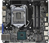
H310M-STX / H310M-STX/COM Motherboard Layout 1 23 RoHS DC Jack CPU_FAN2 CPU_FAN1 DP1 DDR4_A1 DDR4_B1 HDMI1 Audio CODEC VGA1 T: USB 2.0 USB3 B: USB 3.1 Gen1 USB4 Top: RJ-45 9 1 CI1 SPEAKER1 1 4 USB_5_6 5 1 COM1 Mic In 1 6 USB 3.1 Gen1 USB_2 Intel Chipset M2_1_CT1 BIOS ROM M2_2_CT1 - ASRock H310M-STX | Quick Installation Guide - Page 4
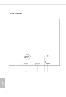
Back Side View CMOS Battery SATA3 SATA3 10 11 12 13 2 English - ASRock H310M-STX | Quick Installation Guide - Page 5
Slots (DDR4_A1, DDR4_B1) 3 CPU Fan Connector (CPU_FAN1) 4 MONO Speaker Header (SPEAKER1) 5 USB 2.0 Header (USB_5_6) 6 COM Port Header (COM1) (for H310M-STX/COM only) 7 System Panel Header (PANEL1) 8 Audio Header (AUDIO3) 9 Chassis Intrusion Header (CI1) 10 SATA3 Connector (SATA1) 11 SATA3 Connector - ASRock H310M-STX | Quick Installation Guide - Page 6
Front Panel 1 2 3 4 No. Description 1 Headphone/Headset Jack (AUDIO1) 2 USB 3.1 Gen1 Type-A Port (USB_1) No. Description 3 USB 3.1 Gen1 Type-C Port (USB3_2) 4 Microphone Input (AUDIO2) English 4 - ASRock H310M-STX | Quick Installation Guide - Page 7
Rear Panel H310M-STX / H310M-STX/COM 7 1 2 3 4 5 6 No. Description 1 DC Jack (Supports 19V DC Power Adapters) 2 Display Port 3 HDMI Port No. Description 4 D-Sub Port 5 USB 2.0 Port (USB_3) 6 USB 3.1 Gen1 Port (USB_4) 7 LAN RJ-45 Port* * There are - ASRock H310M-STX | Quick Installation Guide - Page 8
and the BIOS software might be updated, the content of this documentation will be subject to change without notice. 1.1 Package Contents • H310M-STX / H310M-STX/COM Motherboard (Mini-STX Form Factor) • H310M-STX / H310M-STX/COM Quick Installation Guide • H310M-STX / H310M-STX/COM Support CD - ASRock H310M-STX | Quick Installation Guide - Page 9
H310M-STX / H310M-STX/COM 1.2 Specifications Platform • Mini-STX Form Factor CPU • Supports 9th and 8th Gen Intel® CoreTM Processors (Socket 1151) • Supports CPU up to 65W • 5 Power Phase design • Supports Intel® Turbo Boost 2.0 Technology Chipset • Intel® H310 Memory • Dual Channel DDR4 - ASRock H310M-STX | Quick Installation Guide - Page 10
Sync, Deep Color (12bpc), xvYCC and HBR (High Bit Rate Audio) with HDMI Port (Compliant HDMI monitor is required) • Supports HDCP with HDMI and DisplayPort 1.2 Ports • Supports 4K Ultra HD (UHD) playback with HDMI and DisplayPort 1.2 Ports • Realtek ALC233 Audio Codec • 1 x Headphone/Headset Jack - ASRock H310M-STX | Quick Installation Guide - Page 11
COM Port Header (for H310M-STX/COM only) • 1 x Chassis Intrusion Header • 2 x CPU Fan Connectors (2 x 4-pin) • 1 x MONO Speaker Header • 1 x Front Panel Header • 1 x USB 2.0 Header (Supports 2 USB 2.0 ports) (Supports ESD Protection) • 1 x SD Card Socket • 1 x Audio Header BIOS Feature • AMI UEFI - ASRock H310M-STX | Quick Installation Guide - Page 12
risk involved with overclocking, including adjusting the setting in the BIOS, applying Untied Overclocking Technology, or using third-party overclocking for possible damage caused by overclocking. Mini-STX Chassis Support List Vendor SilverStone Technology Inc. AKasa Model VT01S A-STX04-A1B / - ASRock H310M-STX | Quick Installation Guide - Page 13
H310M-STX / H310M-STX/COM Chapter 2 Installation This is a Mini-STX form factor motherboard. Before you install the motherboard, study the configuration of your chassis to ensure that the motherboard fits into it. Pre-installation Precautions Take note of the following precautions before you install - ASRock H310M-STX | Quick Installation Guide - Page 14
2.1 Installing the CPU 1. Before you insert the 1151-Pin CPU into the socket, please check if the PnP cap is on the socket, if the CPU surface is unclean, or if there are any bent pins in the socket. Do not force to insert the CPU into the socket if above situation is found. Otherwise, the CPU will - ASRock H310M-STX | Quick Installation Guide - Page 15
H310M-STX / H310M-STX/COM 3 4 5 13 English - ASRock H310M-STX | Quick Installation Guide - Page 16
Please save and replace the cover if the processor is removed. The cover must be placed if you wish to return the motherboard for after service. 14 English - ASRock H310M-STX | Quick Installation Guide - Page 17
H310M-STX / H310M-STX/COM 2.2 Installing the CPU Fan and Heatsink 1 2 CPU_FAN English 15 - ASRock H310M-STX | Quick Installation Guide - Page 18
allowed to install a DDR, DDR2 or DDR3 memory module into a DDR4 slot; otherwise, this motherboard and SO-DIMM may be damaged. The SO-DIMM only fits in one correct orientation. It will cause permanent damage to the motherboard and the SO-DIMM if you force the SO-DIMM into the slot at - ASRock H310M-STX | Quick Installation Guide - Page 19
H310M-STX / H310M-STX/COM 1 2 3 17 English - ASRock H310M-STX | Quick Installation Guide - Page 20
jumper caps over these headers and connectors. Placing jumper caps over the headers and connectors will cause permanent damage to the motherboard. System Panel Header (9-pin PANEL1) (see p.1, No. 7) PLED+ PLEDPWRBTN# GND 1 GND RESET# GND HDLEDHDLED+ Connect the power button, reset button and - ASRock H310M-STX | Quick Installation Guide - Page 21
H310M-STX / H310M-STX/COM MONO Speaker Header 1 (4-pin SPEAKER1) (see p.1, No. 4) Front_LFront_L+ Front_R+ DUMMY GND P+ P- USB_PWR GND P+ PUSB_PWR 1 There is one header on this motherboard. This USB 2.0 header can support two ports. CPU Fan Connectors (4-pin CPU_FAN1) (see p.1, No. 3) (4-pin - ASRock H310M-STX | Quick Installation Guide - Page 22
Serial Port Header (for H310M-STX/COM only) (9-pin COM1) (see p.1, No. 6) RI NC This COM1 header RTS GND CTS DSR supports a serial port TXD DTR module. DCD RXD 1 Chassis Intrusion Header (2-pin CI1) (see p.1, No. 9) GND Signal 1 This motherboard supports CASE OPEN detection feature - ASRock H310M-STX | Quick Installation Guide - Page 23
H310M-STX / H310M-STX/COM 2.5 M.2 WiFi/BT Module and Intel® CNVi (Integrated WiFi/BT) Installation Guide The M.2, also known as the Next Generation Form Factor (NGFF), is a small size and versatile card edge connector that aims to replace mPCIe and mSATA. The M.2 Socket (Key E) supports type 2230 - ASRock H310M-STX | Quick Installation Guide - Page 24
A A 20o A Step 3 Gently insert the WiFi/BT module or Intel® CNVi (Integrated WiFi/ BT) into the M.2 slot. Please be aware that the module only fits in one orientation. Step 4 Tighten the screw with a screwdriver to secure the module into place. Please do not overtighten the screw as this might - ASRock H310M-STX | Quick Installation Guide - Page 25
H310M-STX / H310M-STX/COM 2.6 M.2_SSD (NGFF) Module Installation Guide The M.2, also known as the Next Generation Form Factor (NGFF), is a small size and versatile card edge connector that aims to replace mPCIe and mSATA. The Ultra M.2 Socket supports type 2280 M.2 SATA3 6.0 Gb/s module and M.2 PCI - ASRock H310M-STX | Quick Installation Guide - Page 26
M.2_SSD (NGFF) Module Support List Vendor ADATA ADATA Apacer Intel Intel INTEL INTEL INTEL INTEL Kingston PATRIOT PLEXTOR PLEXTOR 240G WD BLUE WDS100T1B0B WD Green WDS240G1G0B-00RC30 English For the latest updates of M.2_SSD (NFGG) module support list, please visit our website for details. 24 - ASRock H310M-STX | Quick Installation Guide - Page 27
H310M-STX / H310M-STX/COM 2.7 SD Card Installation Guide 1. Locate the SD Card Slot on the back side of the motherboard. 2. Carefully insert the SD Card into the slot until it clicks. 25 English - ASRock H310M-STX | Quick Installation Guide - Page 28
sowie die BIOS-Software aktualisiert werden können, kann der Inhalt dieser Dokumentation ohne Ankündigung geändert werden. 1.1 Lieferumfang • H310M-STX-/ H310M-STX/COM-Motherboard (Mini-STX-Formfaktor) • H310M-STX-/ H310M-STX/COM-Schnellinstallationsanleitung • H310M-STX-/ H310M-STX/COM-Support-CD - ASRock H310M-STX | Quick Installation Guide - Page 29
H310M-STX / H310M-STX/COM 1.2 Technische Daten Plattform • Mini-STX-Formfaktor Prozessor • Unterstützt Intel® CoreTM-Prozessoren (Sockel 1151) der 8ten & 9ten Generation • Unterstützt CPU bis 65 W • 5-Leistungsphasendesign • Unterstützt Intel® Turbo Boost 2.0-Technologie - ASRock H310M-STX | Quick Installation Guide - Page 30
Audio LAN Frontblende, E/A • Max. geteilter Speicher 1024 MB * Die Größe des maximalen Freigabespeichers kann je nach Betriebssystem variieren. • Drei Grafikkarten-Ausgangsoptionen: D-Sub, HDMI und DisplayPort 1.2 * Unterstützt bis zu 2 Displays gleichzeitig • Unterstützt HDMI mit maximaler Auflö - ASRock H310M-STX | Quick Installation Guide - Page 31
Gbit/s)* * Unterstützt NVMe-SSD als Bootplatte • 1 x COM-Anschluss-Stiftleiste (nur für H310M-STX/ COM) • 1 x Gehäuseeingriff-Stiftleiste • 2 x CPU-Lüfteranschlüsse (2 x 4- • 1 x Audio-Stiftleiste • AMI-UEFI-Legal-BIOS mit Unterstützung mehrsprachiger grafischer Benutzerschnittstellen • ACPI 6.0- - ASRock H310M-STX | Quick Installation Guide - Page 32
dass mit einer Übertaktung, zu der die Anpassung von BIOS-Einstellungen, die Anwendung der Untied Overclocking Technology oder die Nutzung die durch eine Übertaktung verursacht wurden. Liste der unterstützten Mini-STX-Gehäuse Anbieter SilverStone Technology Inc. AKasa Modell VT01S A-STX04-A1B - ASRock H310M-STX | Quick Installation Guide - Page 33
-STX / H310M-STX/COM 1.3 Integrierte Stiftleisten und Anschlüsse Integrierte Stiftleisten und Anschlüsse sind KEINE Jumper. Bringen Sie KEINE Jumper-Kappen an diesen Stiftleisten und Anschlüssen an. Durch Anbringen von Jumper-Kappen an diesen Stiftleisten und Anschlüssen können Sie das Motherboard - ASRock H310M-STX | Quick Installation Guide - Page 34
USB 2.0-Stiftleiste (9-polig, USB_5_6) (siehe S. 1, Nr. 5) DUMMY GND P+ P- USB_PWR GND P+ PUSB_PWR 1 Es gibt eine Stiftleiste an diesem Motherboard. Diese USB 2.0-Stiftleiste unterstützt zwei Ports. CPU-Lüfteranschlüsse (4-polig, CPU_FAN1) (siehe S. 1, Nr. 3) (4-polig, CPU_FAN2) (siehe S. 1, Nr - ASRock H310M-STX | Quick Installation Guide - Page 35
Anschluss (nur für H310M-STX/COM) (9-polig, COM1) (siehe S. 1, Nr. 6) RI RTS GND TXD DCD 1 NC CTS DSR DTR RXD Diese COM1-Stiftleiste unterstützt ein Modul für serielle Ports. Gehäuseeingriff-Stiftleiste (2-polig, CI1) (siehe S. 1, Nr. 9) GND Signal Dieses Motherboard 1 unterstützt die - ASRock H310M-STX | Quick Installation Guide - Page 36
logiciel BIOS pouvant être mises à jour, le contenu de ce document est soumis à modification sans préavis. 1.1 Contenu de l'emballage • Carte mère H310M-STX / H310M-STX/COM (facteur de forme Mini-STX) • Guide d'installation rapide H310M-STX / H310M-STX/COM • CD d'assistance H310M-STX / H310M-STX/COM - ASRock H310M-STX | Quick Installation Guide - Page 37
H310M-STX / H310M-STX/COM 1.2 Spécifications Plateforme • Facteur de forme Mini-STX Processeur • Prend en charge les processeurs 9e et 8e génération Intel® CoreTM (socket 1151) • Prend en charge les unités centrales jusqu'à 65W • Alimentation à 5 phases • Prend - ASRock H310M-STX | Quick Installation Guide - Page 38
• Mémoire partagée max. 1024 Mo * La taille de la mémoire partagée maximale peut varier selon les différents systèmes d'exploitation. • Trois options de sortie graphique : D-Sub, HDMI et DisplayPort 1.2 * Prend en charge jusqu'à 2 écrans simultanément • Prend en charge la technologie HDMI avec ré - ASRock H310M-STX | Quick Installation Guide - Page 39
H310M-STX / H310M-STX/COM Connectique du panneau arrière Stockage Connecteur Caractéristiques du BIOS Surveillance du maté charge les SSD NVMe comme disques de démarrage • 1 x embase port COM (uniquement sur H310M-STX/COM) • 1 x embase d'intrusion châssis • 2 x connecteurs pour ventilateur de CPU - ASRock H310M-STX | Quick Installation Guide - Page 40
que l'overclocking présente certains risques, incluant des modifications du BIOS, l'application d'une technologie d'overclocking déliée et l'utilisation d'outils Liste de prise en charge du châssis Mini-STX Fournisseur SilverStone Technology Inc. AKasa Modèle VT01S A-STX04-A1B / A-STX04-M1B - ASRock H310M-STX | Quick Installation Guide - Page 41
H310M-STX / H310M-STX/COM 1.3 Embases et connecteurs de la carte mère Les embases et connecteurs situés sur la carte NE SONT PAS des cavaliers. Ne placez JAMAIS de - ASRock H310M-STX | Quick Installation Guide - Page 42
Embase de haut-parleur 1 MONO (SPEAKER1 à 4 broches) (voir p.1, No. 4) Front_LFront_L+ Front_R+ Front_R- Veuillez brancher le haut-parleur du châssis sur cette embase. Connecteurs Serial ATA3 (voir p.2, No. 10 et 11) 1 Broche 1 2 3 4 5 6 7 8 9 10 Nom du signal GND LVDS_TX+ LVDS_TX- GND GND - ASRock H310M-STX | Quick Installation Guide - Page 43
H310M-STX / H310M-STX/COM Embase port série (uniquement sur H310MSTX/COM) (COM1 à 9 broches) (voir p.1, No. 6) RI NC Cette embase COM1 prend en RTS GND CTS DSR charge un - ASRock H310M-STX | Quick Installation Guide - Page 44
scheda madre H310M-STX / H310M-STX/COM. In questo manuale, i capitoli 1 e 2 contengono un'introduzione alla scheda madre e le guide di installazione passo passo. Il capitolo 3 contiene la guida operativa del software e le utility. Il capitolo 4 contiene la guida alla configurazione BIOS. Dato che - ASRock H310M-STX | Quick Installation Guide - Page 45
H310M-STX / H310M-STX/COM 1.2 Specifiche Piattaforma • Form Factor Mini-STX CPU • Supporta processori 9th Gen e 8th Generation Intel® della scheda video UHD Intel® e le uscite VGA possono essere supportate soltanto con processori con GPU integrata. • Supporta la videografica integrata della - ASRock H310M-STX | Quick Installation Guide - Page 46
• Memoria condivisa max. 1.024MB * Le dimensioni massime della memoria condivisa possono variare tra i diversi sistemi operativi. • Tre opzioni di output grafico: D-Sub, HDMI e DisplayPort 1.2 * Supporta fino a 2 display simultaneamente • Supporta HDMI con risoluzione massima fino a 4K x 2K (4096 x - ASRock H310M-STX | Quick Installation Guide - Page 47
H310M-STX / H310M-STX/COM I/O pannello posteriore Archiviazione Connettore Funzionalità BIOS Hardware Monitor • 1 x connettore * Supporto di SSD NVMe come disco d'avvio • 1 x connettore porta COM ((solo per H310M-STX/COM) • 1 x connettore intrusione telaio • 2 x connettori ventola CPU (2 x 4 pin - ASRock H310M-STX | Quick Installation Guide - Page 48
di overclocking, inclusa la regolazione delle impostazioni nel BIOS, l'applicazione di tecnologia di Untied Overclocking o l' riterremo responsabili per possibili danni provocati da overclocking. Elenco telai Mini-STX supportati Venditore SilverStone Technology Inc. AKasa Modello VT01S A-STX04 - ASRock H310M-STX | Quick Installation Guide - Page 49
H310M-STX / H310M-STX/COM 1.3 Header e connettori su scheda Gli header e i connettori sulla scheda NON sono jumper. NON posizionare cappucci del jumper su questi header e connettori. Il posizionamento di - ASRock H310M-STX | Quick Installation Guide - Page 50
Connettore casse MONO 1 (SPEAKER1 a 4 pin) (vedere pag. 1, n. 4) Front_LFront_L+ Front_R+ Front_R- Collegare l'altoparlante dello chassis a questo header. Connettori Serial ATA3 (vedere pag. 2, n. 10 e 11) 1 Nome del PIN PIN segnale 1 GND 11 2 LVDS_TX+ 12 3 LVDS_TX- 13 4 GND 14 5 - ASRock H310M-STX | Quick Installation Guide - Page 51
H310M-STX / H310M-STX/COM Connettore porta seriale (solo per H310M-STX/ COM) (COM1 a 9 pin) (vedere pag. 1, n. 6) RI NC Questo header COM1 supporta RTS GND CTS DSR un modulo di porta seriale. TXD DTR DCD RXD 1 Header - ASRock H310M-STX | Quick Installation Guide - Page 52
software de la BIOS podrán ser actualizados, el contenido que aparece en esta documentación estará sujeto a modificaciones sin previo aviso. 1.1 Contenido del paquete • Placa base H310M-STX / H310M-STX/COM (factor de forma Mini-STX) • Guía de instalación rápida de H310M-STX / H310M-STX/COM • CD de - ASRock H310M-STX | Quick Installation Guide - Page 53
H310M-STX / H310M-STX/COM 1.2 Especificaciones Plataforma • Factor de forma Mini-STX CPU • Compatible con 9a y 8a generación de procesadores Intel® CoreTM (Socket 1151) • Admite CPU de hasta 65 W. • Diseño de 5 fases de alimentación • Admite la tecnología - ASRock H310M-STX | Quick Installation Guide - Page 54
• Memoria máxima compartida de 1.024MB * El tamaño de memoria compartida máxima puede variar en función de los sistemas operativos. • Tres opciones de salida de gráficos: D-Sub, HDMI y DisplayPort 1.2 * Admite hasta 2 pantallas simultáneamente • Admite la tecnología HDMI con una resolución máxima de - ASRock H310M-STX | Quick Installation Guide - Page 55
H310M-STX / H310M-STX/COM E/S en panel posterior Almacenamiento Conector Función de la BIOS Monitor de hardware • 1 x Conector de de NVMe como disco de arranque • 1 x Base de conexiones de puerto COM (solo para H310M-STX/ COM) • 1 x Base de conexiones para manipulación del chasis • 2 x Conectores - ASRock H310M-STX | Quick Installation Guide - Page 56
implícito en las operaciones de overclocking, incluido el ajuste de la BIOS, aplicando la tecnología de overclocking liberada o utilizando las herramientas de por el overclocking. Lista de compatibilidad del chasis Mini-STX Proveedor SilverStone Technology Inc. AKasa Modelo VT01S A-STX04-A1B / - ASRock H310M-STX | Quick Installation Guide - Page 57
H310M-STX / H310M-STX/COM 1.3 Conectores y cabezales incorporados Los cabezales y conectores incorporados NO son puentes. NO coloque tapas de puente sobre estos cabezales y conectores. Si coloca tapas de puente - ASRock H310M-STX | Quick Installation Guide - Page 58
Base de conexiones 1 MONO (SPEAKER1 de 4 contactos) (consulte la pág.1, N.º 4) Front_LFront_L+ Front_R+ Front_R- Conecte el altavoz del chasis a este cabezal. Conectores Serie ATA3 (consulte la pág. 2, N.º 10 1 y 11) CONTACTO 1 2 3 4 5 6 7 8 9 10 Nombre de la señal GND LVDS_TX+ LVDS_TX- GND GND - ASRock H310M-STX | Quick Installation Guide - Page 59
Base de conexiones de puerto serie (solo para H310M-STX/COM) (COM1 de 9 contactos) (consulte la pág.1, N.º 6) RI NC Este cabezal COM1 admite un RTS GND CTS DSR módulo de puerto serie. TXD DTR DCD RXD 1 - ASRock H310M-STX | Quick Installation Guide - Page 60
1 H310M-STX / H310M-STX/COM 1 и 2 3 4 BIOS. BIOS 1.1 H310M-STX / H310M-STX/COM Mini-STX H310M-STX / H310M-STX/COM H310M-STX / H310M-STX/COM • 1 2 Serial ATA (SATA 1 M.2 (M2*2 1 WiFi (M2*2 58 - ASRock H310M-STX | Quick Installation Guide - Page 61
H310M-STX / H310M-STX/COM 1.2 Mini-STX ЦП 9го и 8 Intel® CoreTM (Socket 1151) 65 Вт. 5 Intel® Turbo Boost 2.0 Чипсет • Intel® H310 Память DDR4 • 2 x DDR4 SO-DIMM DDR4 2666/2400/2133 без ECC - ASRock H310M-STX | Quick Installation Guide - Page 62
Звук LAN 1024 D-Sub, HDMI и DisplayPort 1.2 2 HDMI 4K x 2K (4096x2160 30 D-Sub 1920x1200 при 60 DisplayPort 1.2 4K x 2K (4096x2304) при 60 Auto Lip Sync, Deep Color (12 xvYCC и HBR (High Bit Rate Audio HDMI HDMI HDCP HDMI и DisplayPort 1.2 4K Ultra HD (UHD HDMI и - ASRock H310M-STX | Quick Installation Guide - Page 63
6,0 NCQ, AHCI • 1 Ultra M.2 M.2 SATA3 типа 2280 6,0 M.2 PCI Express Gen3 x4 (32 SSD NVMe. • 1 COM H310M-STX/COM) • 1 2 2 х 4 1 1 1 USB 2.0 (2 порта USB 2.0 1 SD • 1 • AMI UEFI Legal BIOS ACPI 6.0 SMBIOS 2.7 DRAM 12 В, +5 В, +3,3 В, Vcore ЦП 61 - ASRock H310M-STX | Quick Installation Guide - Page 64
• Microsoft® Windows® 10 (64 • FCC, CE ErP/EuP ErP/EuP) BIOS Untied Overclocking Mini-STX SilverStone Technology Inc. AKasa VT01S A-STX04-A1B / A-STX04-M1B 62 - ASRock H310M-STX | Quick Installation Guide - Page 65
H310M-STX / H310M-STX/COM 1.3 9 PANEL1) PLED+ PLEDPWRBTN# GND 1, № 7) 1 GND RESET# GND HDLEDHDLED+ PWRBTN RESET PLED S1/S3 S4 S5 HDLED 63 - ASRock H310M-STX | Quick Installation Guide - Page 66
MONO 1 (4 SPEAKER1 1, № 4) Front_LFront_L+ Front_R+ Front_R- Serial ATA3 2, № 10 и 11) 1 20 1 2 3 4 5 6 7 8 9 10 GND LVDS_TX+ LVDS_TX- GND GND LVDS_RXLVDS_RX+ GND GND GND 11 12 13 14 15 16 17 18 19 20 Н.П. 5V 5V 5V 5V 5V Н.П. GND GND GND SATA3 SATA 6,0 - ASRock H310M-STX | Quick Installation Guide - Page 67
H310M-STX / H310M-STX/COM 1 H310M-STX/ COM) (9 COM1 1, № 6) RI RTS GND TXD DCD 1 NC CTS DSR DTR RXD COM1 2 CI1 1, № 9) GND Signal 1 CMOS 2, № 12) CMOS CMOS CMOS CMOS 5 AUDIO3 1, № 8) 1 Audio-R Audio-L Jack detect GND 65 - ASRock H310M-STX | Quick Installation Guide - Page 68
do BIOS podem ser atualizadas, o conteúdo desta documentação estará sujeito a alterações sem aviso prévio. 1.1 Conteúdo da embalagem • Placa mãe H310M-STX / H310M-STX/COM (Fator de Forma Mini-STX) • Guia de Instalação Rápida H310M-STX / H310M-STX/COM • CD de Suporte H310M-STX / H310M-STX/COM - ASRock H310M-STX | Quick Installation Guide - Page 69
H310M-STX / H310M-STX/COM 1.2 Especificações Plataforma • Formato Mini-STX CPU • Suporta 9ª Ger. e 8ª Geraão de Processadores Intel® CoreTM (Soquete 1151) • Suporta CPU até 65W • Design com 5 fases de alimentação • Suporta a tecnologia Intel® Turbo Boost 2.0 Chipset • - ASRock H310M-STX | Quick Installation Guide - Page 70
• Memória compartilhada máxima de 1.024MB * O tamanho da memória compartilhada máxima pode variar de diferentes sistemas operacionais. • Três opções de saída de gráficos: D-Sub, HDMI e DisplayPort 1.2 * Suporta até 2 monitores simultaneamente • Suporta HDMI com resolução máx. até 4K x 2K (4096x2160) - ASRock H310M-STX | Quick Installation Guide - Page 71
H310M-STX / H310M-STX/COM E/S do painel posterior Armazenamento Conector Funções da BIOS Monitor de hardware • 1 x 32 Gb/s)* * Suporta NVMe SSD nos discos de inicialização • 1 x Conector Porta COM (para H310M-STX/COM apenas) • 1 x Gabinete de Alimentação de Instrusão • 2 x Conectores de ventilador - ASRock H310M-STX | Quick Installation Guide - Page 72
um certo risco envolvendo overclocking, incluindo o ajuste das definições na BIOS, a aplicação de tecnologia Untied Overclocking ou a utilização de causados pelo overclocking. Lista de Suporte do Chassi Mini-STX Vendedor SilverStone Technology Inc. AKasa Modelo VT01S A-STX04-A1B / A- - ASRock H310M-STX | Quick Installation Guide - Page 73
H310M-STX / H310M-STX/COM 1.3 Suportes e conectores onboard Os conectores e suportes onboard NÃO são jumpers. NÃO coloque tampas de jumpers sobre estes terminais e conectores Colocar tampas de jumpers sobre os terminais e conectores - ASRock H310M-STX | Quick Installation Guide - Page 74
Cabeçote do 1 Alto-falante MONO (SPEAKER1 de 4 pinos) (ver p.1, N.º 4) Front_LFront_L+ Front_R+ Front_R- Por favor, conecte o alto-falante do chassi a este suporte. Conectores série ATA3 (ver p.2, N.º 10 e 11) 1 PIN Nome do Sinal PIN 1 GND 11 2 LVDS_TX+ 12 3 LVDS_TX- 13 4 GND 14 5 - ASRock H310M-STX | Quick Installation Guide - Page 75
H310M-STX / H310M-STX/COM Conector Porta Serial (para H310M-STX/COM apenas) (COM1 de 9 pinos) (ver p.1, N.º 6) Suporte de intrusão do chassi (CI1 de 2 pinos) (ver p.1, N.º 9) RI NC Este suporte COM1 recebe um RTS GND CTS - ASRock H310M-STX | Quick Installation Guide - Page 76
BIOS mogą zostać zaktualizowane, zawartość tej dokumentacji może zostać zmieniona bez powiadomienia. 1.1 Zawartość opakowania • Płyta główna H310M-STX / H310M-STX/COM (współczynnik kształtu Mini-STX) • Skrócona instrukcja instalacji H310M-STX / H310M-STX/COM • Pomocnicza płyta CD H310M-STX / H310M - ASRock H310M-STX | Quick Installation Guide - Page 77
H310M-STX / H310M-STX/COM 1.2 Specyfikacje Platforma • Współczynnik kształtu Mini-STX CPU • Obsługa 9-ej i 8-ej generacji procesorów Intel® CoreTM (Socket 1151) • Obsługa CPU do 65 W • Sekcja zasilania 5 Power Phase Design • Obsługa technologii Intel® - ASRock H310M-STX | Quick Installation Guide - Page 78
• Maks. współdzielona pamięć 1 024MB * Wielkość maksymalnej współdzielonej pamięci zależy od systemów operacyjnych. • Opcje trzech wyjść graficznych: D-Sub, HDMI i DisplayPort 1.2 * Obsługa do 2 monitorów jednocześnie • Obsługa HDMI z maks. rozdzielczością do 4K x 2K (4096x2160) przy 30Hz • Obsługa - ASRock H310M-STX | Quick Installation Guide - Page 79
H310M-STX / H310M-STX/COM Polski Tylny panel Wejścia/ Wyjścia Przechowywanie Złącze Funkcja BIOS Monitor sprzętu • 1 x gniazdo zasilania DC (zgodne z zasilaczem 19 V)* * Korzystać z zasilacza 120 W dla CPU 65 W i zasilacza 90 W dla CPU 35 W. • 1 x port D-Sub • 1 x port HDMI • 1 x DisplayPort 1.2 - ASRock H310M-STX | Quick Installation Guide - Page 80
zane z pewnym ryzykiem, włącznie z regulacją ustawień w BIOS, zastosowaniem Untied Overclocking Technology lub używaniem narzędzi przetaktowywania żliwe uszkodzenia spowodowane przetaktowywaniem. Lista obsługiwanych obudów Mini-STX Dostawca SilverStone Technology Inc. AKasa Model VT01S A-STX04- - ASRock H310M-STX | Quick Installation Guide - Page 81
H310M-STX / H310M-STX/COM 1.3 Wbudowane złącza główkowe i inne złącza Wbudowane złącza główkowe i inne złącza są bezzworkowe. NIE należy umieszczać zworek nad tymi złączami główkowymi i złączami. Umieszczanie zworek nad złączami głó - ASRock H310M-STX | Quick Installation Guide - Page 82
Złącze główkowe głośnika MONO Podłącz to tego złącza 1 Front_L- Front_L+ główkowego głośnik obudowy. (4-pinowe SPEAKER1) (sprawdź p.1, Nr 4) Front_R+ Front_R- Złącza Serial ATA3 (sprawdź p.2, Nr 10 i 11) Nazwa Styk sygnału 1 GND 2 LVDS_TX+ 3 LVDS_TX- 4 GND 5 GND 6 LVDS_RX- 7 - ASRock H310M-STX | Quick Installation Guide - Page 83
H310M-STX / H310M-STX/COM Szeregowy port główkowy (tylko dla H310M-STX/ COM) (9-pinowe COM1) (sprawdź p.1, Nr 6) To złącze główkowe COM1 RI RTS NC CTS obsługuje moduł portu GND TXD DSR szeregowego. DTR DCD RXD 1 Złącze głó - ASRock H310M-STX | Quick Installation Guide - Page 84
한 국 어 1 개요 H310M-STX / H310M-STX/COM 1 장과 2 3 4 BIOS BIOS 1.1 • H310M-STX / H310M-STX/COM Mini-STX H310M-STX / H310M-STX/COM H310M-STX / H310M-STX/COM 지원 CD • I/O 1 ATA (SATA 2 M.2 소켓 (M2*2 1 WiFi 모듈 (M2*2 1 82 - ASRock H310M-STX | Quick Installation Guide - Page 85
H310M-STX / H310M-STX/COM 1.2 규격 플랫폼 CPU • Mini-STX 폼 팩터 • 9 세대 및 8 세대 Intel® CoreTM 1151 65W 의 CPU 지원 • 5 Intel® Turbo Boost 2.0 • Intel® H310 DDR4 DDR4 SO-DIMM 슬롯 2 개 • DDR4 2666/2400/2133 비 ECC 64GB • Intel® Extreme Memory Profile (XMP) 2.0 지원 • - ASRock H310M-STX | Quick Installation Guide - Page 86
한 국 어 1,024MB D-Sub, HDMI 및 DisplayPort 1.2 * 최대 2 HDMI 4K x 2K (4096x2160) @ 30Hz) • D-Sub 1920x1200 @ 60Hz) • DisplayPort 1.2 4K x 2K (4096x2304) @ 60Hz) • Auto Lip Sync, Deep Color (12bpc), xvYCC 및 HBR (High Bit Rate Audio) (HDMI HDMI 호환 모 HDCP (HDMI 및 DisplayPort 1.2 HDMI 및 - ASRock H310M-STX | Quick Installation Guide - Page 87
SATA3 6.0 Gb/s 모듈 및 Gen3 M.2 PCI Express 모듈을 4 개 (32 Gb/s * NVMe SSD 커넥터 • COM 1 개 (H310M-STX/COM 1 개 • CPU 2 x 4 핀 ) 2 1 1 개 • USB 2.0 헤더 1 개 (USB 2.0 포트 2 ESD SD 1 1 개 BIOS 기능 GUI AMI UEFI 적합형 BIOS • ACPI 6.0 SMBIOS 2.7 지원 • DRAM • CPU CPU CPU CPU CPU 12V, +5V, +3.3V - ASRock H310M-STX | Quick Installation Guide - Page 88
OS 인증 • Microsoft® Windows® 10 64- 비트 • FCC, CE • ErP/EuP ErP/EuP BIOS Untied Overclocking Technology Mini-STX 벤더 SilverStone Technology Inc. AKasa 모델 VT01S A-STX04-A1B / A-STX04-M1B 한 국 어 86 - ASRock H310M-STX | Quick Installation Guide - Page 89
H310M-STX / H310M-STX/COM 1.3 9 핀 PANEL1) (1 7 PLED+ PLEDPWRBTN# GND 1 GND RESET# GND HDLEDHDLED+ PWRBTN RESET PLED LED LED S1/S3 LED S4 S5 LED HDLED LED LED LED LED LED 한국어 87 - ASRock H310M-STX | Quick Installation Guide - Page 90
한 국 어 MONO 1 (4 핀 SPEAKER1) (1 4 Front_LFront_L+ Front_R+ Front_R- 시리얼 ATA3 커넥터 (2 10 및 11 PIN 1 GND 2 LVDS_TX+ 3 LVDS_TX- 4 GND 5 GND 6 LVDS_RX- 7 LVDS_RX+ 8 GND 9 GND 10 GND 1 PIN 11 12 13 14 15 16 17 18 19 20 20 N/A 5V 5V 5V 5V 5V N/A GND GND GND SATA3 - ASRock H310M-STX | Quick Installation Guide - Page 91
H310M-STX / H310M-STX/COM H310M-STX/ COM 전용 ) (9 핀 COM1) (1 6 RI RTS GND TXD DCD 1 이 COM1 NC CTS DSR DTR RXD 2 핀 CI1) (1 9 GND Signal 1 투명 CMOS 패드 (2 12 CMOS CMOS CMOS CMOS 5 핀 AUDIO3) (1 8 1 Audio-R Audio-L - ASRock H310M-STX | Quick Installation Guide - Page 92
日本語 1 ͡Ίʹ H310M-STX / H310M-STX/COM 1 ষͱୈ 2 3 4 ষʹɺBIOS BIOS 1.1 • H310M-STX / H310M-STX/COM STX H310M-STX / H310M-STX/COM H310M-STX / H310M-STX/COM αϙʔτ CD • 1 x I/O 2 x γϦΞϧ ATA (SATA 1 x M.2 M2*2 1 x WiFi M2*2 90 - ASRock H310M-STX | Quick Installation Guide - Page 93
日本語 H310M-STX / H310M-STX/COM 1.2 仕様 • ϛχ STX CPU • ୈ 9 8 ੈ Intel® CoreTM οτ 1151ʣ • ࠷େ 65W ·Ͱͷ CPU ʹରԠ • 5 • Intel 2.0 νοϓηοτ • Intel® H310 ϝϞϦ DDR4 2 x DDR4 SO-DIMM DDR4 2666/2400/2133 ϊϯ ECC 64GB • Intel XMPʣ2.0 DIMM εϩοτʹ 15 • 1 x M.2 ιέοτ (Key E)ɺλΠϓ - ASRock H310M-STX | Quick Installation Guide - Page 94
日本語 1,024MB 3 D-SubɺHDMIɺ͓Αͼɺ DisplayPort 1.2 * ࠷େ 2 HDMI 4K x 2K (4096x2160) @ 30Hz • D-Sub 1920x1200 @60Hz • DisplayPort 1.2 4K x 2K (4096x2304) @ 60Hz • HDMI 12bpcʣɺ xvYCCɺ͓ΑͼɺHBR ʢHDMI HDMI ϙʔτͱ DisplayPort 1.2 ϙʔτͰ HDCP HDMI ϙʔτͱ DisplayPort 1.2 ϙʔτͰ 4K Ultra HDʢUHDʣ ΦʔσΟΦ - ASRock H310M-STX | Quick Installation Guide - Page 95
Gb/s Gen3 x4 (32 Gb/s) ·Ͱͷ M.2 PCI Express NVMe SSD ʹରԠ ίωΫλ • 1 x COM H310M-STX/COM 1 x 2 x CPU 2 x 4 ϐϯʣ • 1 x 1 x 1 x USB 2.0 ϔομʔʢ2 ͭͷ USB 2.0 ์ిʢESD • 1 x SD 1 x BIOS ػೳ • AMI UEFI Legal BIOS GUI ACPI 6.0 SMBIOS 2.7 DRAM • CPU CPU CPU CPU CPU 12Vɺ+5V - ASRock H310M-STX | Quick Installation Guide - Page 96
OS ೝূ • Microsoft® Windows® 10 64-bit • FCCɺCE • ErP/EuP Readʢy ErP/EuP BIOS ミニ STX ϕϯμʔ SilverStone Technology Inc. AKasa Ϟσϧ VT01S A-STX04-A1B / A-STX04-M1B 日本語 94 - ASRock H310M-STX | Quick Installation Guide - Page 97
日本語 H310M-STX / H310M-STX/COM 1.3 9 ϐϯ PANEL1ʣ ʢp.1ɺNo. 7 ࢀরʣ PLED+ PLEDPWRBTN# GND 1 GND RESET# GND HDLEDHDLED+ PWRBTN RESET PLED LED LED S1/S3 LED S4 S5 LED HDLED LED LED LED LED LED 95 - ASRock H310M-STX | Quick Installation Guide - Page 98
日本語 MONO 1 μʔ ʢ4 ϐϯ SPEAKER1ʣ ʢp.1ɺNo. 4 ࢀরʣ Front_LFront_L+ Front_R+ Front_R- γϦΞϧ ATA3 ίωΫλ ʢp.2ɺNo. 10 ͓Αͼ 11 Λ 1 ࢀরʣ ϐϯ ৴߸໊ ϐϯ 1 GND 11 2 LVDS_TX+ 12 3 LVDS_TX- 13 4 GND 14 5 GND 15 6 LVDS_RX- 16 7 LVDS_RX+ 17 8 GND 18 9 GND 19 10 GND 20 20 ৴߸໊ N/A 5V 5V 5V - ASRock H310M-STX | Quick Installation Guide - Page 99
H310M-STX / H310M-STX/COM H310M-STX/COM 9 ϐϯ COM1ʣ ʢp.1ɺNo. 6 ࢀরʣ 2 ϐϯ CI1ʣ ʢp.1ɺNo. 9 ࢀরʣ RI RTS GND TXD DCD 1 ͜ͷ COM1 NC CTS DSR DTR ·͢ɻ RXD GND Signal 1 CMOS p.2ɺNo. 12 ࢀরʣ 5 3) ʢp.1ɺNo. 8 ࢀরʣ ΫϦΞ CMOS CMOS CMOS - ASRock H310M-STX | Quick Installation Guide - Page 100
簡体中文 1 简介 H310M-STX / H310M-STX/COM 1 章和第 2 3 4 章包含 BIOS Setup BIOS 1.1 • H310M-STX / H310M-STX/COM 主板(Mini-STX H310M-STX / H310M-STX/COM H310M-STX / H310M-STX/COM 1 x I/O 面板 • 2 x 串行 ATA (SATA 1 x M.2 M2*2 1 x WiFi M2*2 98 - ASRock H310M-STX | Quick Installation Guide - Page 101
簡体中文 H310M-STX / H310M-STX/COM 1.2 规格 平台 CPU • Mini-STX 9 代和第 8 代 Intel® CoreTM 1151 65W 的 CPU • 5 Intel® Turbo Boost 2.0 技术 • Intel® H310 DDR4 2 x DDR4 SO-DIMM DDR4 2666/2400/2133 非 ECC 64GB • 支持 Intel® Extreme Memory Profile (XMP) 2.0 • - ASRock H310M-STX | Quick Installation Guide - Page 102
簡体中文 1,024MB 3 D-Sub、HDMI 和 DisplayPort 1.2 2 HDMI,30Hz 4K x 2K (4096x2160 D-Sub,60Hz 1920x1200 • 支持 DisplayPort 1.2,60Hz 4K x 2K (4096x2304 HDMI HDMI Auto Lip Sync、Deep Color (12bpc), xvYCC 和 HBR 频) • 通过 HDMI 和 DisplayPort 1.2 HDCP • 通过 HDMI 和 DisplayPort 1.2 4K 超高清 (UHD) 播放 音频 - ASRock H310M-STX | Quick Installation Guide - Page 103
SATA3 6.0 Gb/s 和 M.2 PCI Express Gen3 x4 (32 Gb/s))* * 支持 NVMe SSD 接口 • 1 x COM H310M-STX/COM) • 1 x 2 x CPU 2 x 4 针 ) • 1 x 1 x 1 x USB 2.0 2 个 USB 2.0 ESD 1 x SD 1 x BIOS • AMI UEFI Legal BIOS GUI • ACPI 6.0 SMBIOS 2.7 • DRAM 硬件监控 • CPU CPU CPU CPU CPU CASE OPEN - ASRock H310M-STX | Quick Installation Guide - Page 104
• Microsoft® Windows® 10 64-bit • FCC、CE • ErP/EuP ErP/EuP BIOS Mini-STX 供应商 SilverStone Technology Inc. AKasa 型号 VT01S A-STX04-A1B / A-STX04-M1B 簡体中文 102 - ASRock H310M-STX | Quick Installation Guide - Page 105
簡体中文 1.3 H310M-STX / H310M-STX/COM 9 针 PANEL1) (见第 1 页, 第 7 个) PLED+ PLEDPWRBTN# GND 1 GND RESET# GND HDLEDHDLED+ PWRBTN RESET PLED LED LED S1/S3 LED S4 S5) 时,此 LED 熄灭。 HDLED LED LED LED 亮起。 LED LED 103 - ASRock H310M-STX | Quick Installation Guide - Page 106
簡体中文 1 (4 针 SPEAKER1) (见第 1 页, 第 4 个) Front_LFront_L+ Front_R+ Front_R- 串行 ATA3 2 页, 第 10 和 11 个) 针脚 1 2 3 4 5 6 7 8 9 10 信号名称 GND LVDS_TX+ LVDS_TX- GND GND LVDS_RXLVDS_RX+ GND GND GND 1 针脚 11 12 13 14 15 16 17 18 19 20 20 N/A 5V 5V 5V 5V 5V N/A GND GND GND 这两个 SATA3 6.0 Gb/s - ASRock H310M-STX | Quick Installation Guide - Page 107
簡体中文 H310M-STX / H310M-STX/COM H310M-STX/COM) (9 针 COM1) (见第 1 页,第 6 个) 2 针 CI1) (见第 1 页,第 9 个) 此 COM1 RI NC RTS CTS 块。 GND TXD DSR DTR DCD RXD 1 GND Signal CASE OPEN(机箱 1 清除 CMOS Pad (见第 2 页,第 12 个) "清除 CMOS Pad CMOS CMOS - ASRock H310M-STX | Quick Installation Guide - Page 108
簡体中文 SJ/T 11364-2006 10 年。 图一 部件名称 Pb) 镉 (Cd) 汞 (Hg Cr(VI PBB PBDE) X O O O O O X O O O O O O SJ/T 11363-2006 X SJ/T 11363-2006 2002/95/EC 106 - ASRock H310M-STX | Quick Installation Guide - Page 109
繁體中文 H310M-STX / H310M-STX/COM 1 簡介 H310M-STX / H310M-STX/COM 1 章及第 2 3 4 章包含 BIOS BIOS 1.1 • H310M-STX / H310M-STX/COM Mini-STX H310M-STX / H310M-STX/COM H310M-STX / H310M-STX/COM 1 x I/O 2 x Serial ATA (SATA 1 x M.2 插座)(M2*2 1 x WiFi 模組)(M2*2 107 - ASRock H310M-STX | Quick Installation Guide - Page 110
繁體中文 1.2 規格 平台 CPU • Mini-STX 尺寸 9 代及第 8 代 Intel® CoreTM 處理器 (Socket 1151 65W CPU • 5 Intel® Turbo Boost 2.0 技術 • Intel® H310 DDR4 2 x DDR4 SO-DIMM DDR4 2666/2400/2133 非 ECC 64GB • 支援 Intel® Extreme Memory Profile ( - ASRock H310M-STX | Quick Installation Guide - Page 111
繁體中文 H310M-STX / H310M-STX/COM 音訊 LAN 前面板 I/O 1024MB D-Sub、HDMI 及 DisplayPort 1.2 2 4K x 2K (4096x2160) @ 30Hz HDMI 1920x1200 @ 60Hz D-Sub 4K x 2K (4096x2304) @ 60Hz DisplayPort 1.2 HDMI HDMI Auto Lip Sync、Deep - ASRock H310M-STX | Quick Installation Guide - Page 112
2280 M.2 SATA3 6.0 Gb/s 模組與 M.2 PCI Express Gen3 x4 (32 Gb/s))類型 * * 支援 NVMe SSD • 1 x COM H310M-STX/COM) • 1 x 2 x CPU 2 x 4-pin) • 1 x 1 x 1 x USB 2.0 2 個 USB 2.0 1 x SD 1 x • AMI UEFI Legal BIOS 含多語 GUI 支援 • ACPI 6.0 SMBIOS 2.7 • DRAM • CPU CPU CPU CPU CPU 12V、+5V、+3.3V - ASRock H310M-STX | Quick Installation Guide - Page 113
繁體中文 H310M-STX / H310M-STX/COM • Microsoft® Windows® 10 64-bit • FCC、CE • ErP/EuP ready ErP/EuP ready BIOS Mini-STX 廠商 SilverStone Technology Inc. AKasa 型號 VT01S A-STX04-A1B / A-STX04-M1B 111 - ASRock H310M-STX | Quick Installation Guide - Page 114
繁體中文 1.3 (9-pin PANEL1 1 7) PLED+ PLEDPWRBTN# GND 1 GND RESET# GND HDLEDHDLED+ PWRBTN RESET PLED LED LED S1/S3 LED S4 S5) 時,LED HDLED LED LED LED LED LED 112 - ASRock H310M-STX | Quick Installation Guide - Page 115
繁體中文 H310M-STX / H310M-STX/COM (4-pin SPEAKER1 1 4) 1 Front_L- Front_L+ Front_R+ Front_R- Serial ATA3 2 10 與 11) PIN 1 GND 2 LVDS_TX+ 3 LVDS_TX- 4 GND 5 GND 6 LVDS_RX- 7 LVDS_RX+ 8 GND 9 GND 10 GND 1 PIN 11 - ASRock H310M-STX | Quick Installation Guide - Page 116
繁體中文 H310M-STX/COM) (9-pin COM1 1 6) RI RTS GND TXD DCD 1 此 COM1 NC CTS 模組。 DSR DTR RXD 2-pin CI1 1 9) GND Signal 1 清除 CMOS 2 12) 「清除 CMOS CMOS CMOS CMOS 5-pin - ASRock H310M-STX | Quick Installation Guide - Page 117
Bahasa Indonesia H310M-STX / H310M-STX/COM Spesifikasi Platform • Bentuk dan Ukuran Mini-STX CPU • Mendukung Prosesor Generasi ke-9 & Generasi ke-8 Intel® CoreTM (Socket 1151) • Mendukung CPU hingga 65W • Desain 5 Fase Daya • Mendukung Teknologi Intel® Turbo Boost 2.0 Chipset • Intel® - ASRock H310M-STX | Quick Installation Guide - Page 118
Bahasa Indonesia Audio LAN I/O Panel Depan • Maksimum memori bersama 1.024MB * Ukuran memori bersama maksimum bervariasi di berbagai sistem operasi. • Tiga pilihan output grafis: D-Sub, HDMI, dan DisplayPort 1.2 * Mendukung hingga 2 tampilan secara bersamaan • Mendukung HDMI dengan resolusi - ASRock H310M-STX | Quick Installation Guide - Page 119
H310M-STX/ COM) • 1 x Header Chassis Intrusion • 2 x Konektor Kipas CPU (2 x 4-pin) • 1 x Header Speaker Internal • 1 x Header Panel Depan • 1 x Header USB 2.0 (Mendukung 2 port USB 2.0) (Mendukung Perlindungan dari ESD) • 1 x Soket Kartu SD • 1 x Header Audio Fitur BIOS • AMI UEFI Legal BIOS - ASRock H310M-STX | Quick Installation Guide - Page 120
overclocking memiliki risiko tertentu, termasuk menyesuaikan pengaturan pada BIOS, menerapkan Teknologi Untied Overclocking, atau menggunakan alat jawab atas kemungkinan kerusakan karena overclocking. Daftar Dukungan Sasis Mini-STX Vendor SilverStone Technology Inc. AKasa Model VT01S A-STX04-A1B - ASRock H310M-STX | Quick Installation Guide - Page 121
Part 2 Section 2.1077(a) Responsible Party Name: ASRock Incorporation Address: 13848 Magnolia Ave, Chino, CA91710 Phone/Fax No: +1-909-590-8308/+1-909-590-1026 hereby declares that the product Product Name : Motherboard Model Number : H310M-STX / H310M-STX/COM Conforms to the following specifications - ASRock H310M-STX | Quick Installation Guide - Page 122
EU Declaration of Conformity For the following equipment: Motherboard (Product Name) H310M-STX / H310M-STX/COM (Model Designation / Trade Name) ڛEMC -Directive 2014/30/EU (from April 20th, 2016) ☐ EN 55022:2010/AC:2011 Class B ڛEN 55024:2010/A1:2015 ڛ
-
 1
1 -
 2
2 -
 3
3 -
 4
4 -
 5
5 -
 6
6 -
 7
7 -
8
-
9
-
10
-
11
-
12
-
13
-
14
-
15
-
16
-
17
-
18
-
19
-
20
-
21
-
22
-
23
-
24
-
25
-
26
-
27
-
28
-
29
-
30
-
31
-
32
-
33
-
34
-
35
-
36
-
37
-
38
-
39
-
40
-
41
-
42
-
43
-
44
-
45
-
46
-
47
-
48
-
49
-
50
-
51
-
52
-
53
-
54
-
55
-
56
-
57
-
58
-
59
-
60
-
61
-
62
-
63
-
64
-
65
-
66
-
67
-
68
-
69
-
70
-
71
-
72
-
73
-
74
-
75
-
76
-
77
-
78
-
79
-
80
-
81
-
82
-
83
-
84
-
85
-
86
-
87
-
88
-
89
-
90
-
91
-
92
-
93
-
94
-
95
-
96
-
97
-
98
-
99
-
100
-
101
-
102
-
103
-
104
-
105
-
106
-
107
-
108
-
109
-
110
-
111
-
112
-
113
-
114
-
115
-
116
-
117
-
118
-
119
-
120
-
121
-
122
 |
 |
Version 1.0
Published April 2018
Tis device complies with Part 15 of the FCC Rules. Operation is subject to the following
two conditions:
(1)
this device may not cause harmful interference, and
(2)
this device must accept any interference received, including interference that
may cause undesired operation.
CALIFORNIA, USA ONLY
Te Lithium battery adopted on this motherboard contains Perchlorate, a toxic substance
controlled in Perchlorate Best Management Practices (BMP) regulations passed by the
California Legislature. When you discard the Lithium battery in California, USA, please
follow the related regulations in advance.
“Perchlorate Material-special handling may apply, see www.dtsc.ca.gov/hazardouswaste/
perchlorate”