ASRock H470M Pro4 User Manual
ASRock H470M Pro4 Manual
 |
View all ASRock H470M Pro4 manuals
Add to My Manuals
Save this manual to your list of manuals |
ASRock H470M Pro4 manual content summary:
- ASRock H470M Pro4 | User Manual - Page 1
- ASRock H470M Pro4 | User Manual - Page 2
documentation are furnished for informational use only and subject to change without notice, and should not be constructed as a commitment by ASRock. ASRock assumes no responsibility for any errors or omissions that may appear in this documentation. With respect to the contents of this documentation - ASRock H470M Pro4 | User Manual - Page 3
if the goods fail to be of acceptable quality and the failure does not amount to a major failure. If you require assistance please call ASRock Tel : +886-2-28965588 ext.123 (Standard International call charges apply) The terms HDMI® and HDMI High-Definition Multimedia Interface, and the HDMI logo - ASRock H470M Pro4 | User Manual - Page 4
) 18 2.5 Jumpers Setup 19 2.6 Onboard Headers and Connectors 20 2.7 Post Status Checker 26 2.8 CrossFireXTM and Quad CrossFireXTM Operation Guide 27 2.8.1 Installing Two CrossFireXTM-Ready Graphics Cards 27 2.8.2 Driver Installation and Setup 29 2.9 M.2 WiFi/BT Module and Intel® CNVi - ASRock H470M Pro4 | User Manual - Page 5
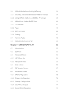
Update & APP Shop 42 3.3.1 UI Overview 42 3.3.2 Apps 43 3.3.3 BIOS & Drivers 46 3.3.4 Setting 47 3.4 Nahimic Audio 48 3.5 ASRock Polychrome SYNC 49 Chapter 4 UEFI SETUP UTILITY 52 4.1 Introduction 52 4.2 EZ Mode 53 4.3 Advanced Mode 54 4.3.1 UEFI Menu Bar 54 4.3.2 Navigation - ASRock H470M Pro4 | User Manual - Page 6
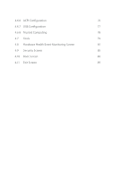
4.6.6 ACPI Configuration 76 4.6.7 USB Configuration 77 4.6.8 Trusted Computing 78 4.7 Tools 79 4.8 Hardware Health Event Monitoring Screen 81 4.9 Security Screen 85 4.10 Boot Screen 86 4.11 Exit Screen 89 - ASRock H470M Pro4 | User Manual - Page 7
the latest VGA cards and CPU support list on ASRock's website as well. ASRock website http://www.asrock.com. 1.1 Package Contents • ASRock H470M Pro4 Motherboard (Micro ATX Form Factor) • ASRock H470M Pro4 Quick Installation Guide • ASRock H470M Pro4 Support CD • 2 x Serial ATA (SATA) Data Cables - ASRock H470M Pro4 | User Manual - Page 8
non-ECC, un- buffered memory * Please refer to Memory Support List on ASRock's website for more information. (http://www.asrock.com/) * CoreTM (i9/i7) support DDR4 up to 2933; CoreTM (i5/i3), Pentium® and Celeron® support DDR4 up to 2666. • Supports ECC UDIMM memory modules (operate in non- ECC mode - ASRock H470M Pro4 | User Manual - Page 9
H470M Pro4 Audio LAN * VP9 10bit and VC-1 are for decode only. * VP8 and VP9 encode are not supported by Windows OS. • Graphics, Media & Compute: Microsoft DirectX 12, OpenGL 4.5, Intel® Built In Visuals, Intel® Quick Sync Video, Hybrid / Switchable Graphics, OpenCL 2.1 • Display & Content - ASRock H470M Pro4 | User Manual - Page 10
M Key type 2280 M.2 SATA3 6.0 Gb/s module and M.2 PCI Express module up to Gen3 x2 (16 Gb/s)** ** Supports Intel® OptaneTM Technology ** Supports NVMe SSD as boot disks ** Supports ASRock U.2 Kit Connector • 1 x SPI TPM Header • 1 x Chassis Intrusion and Speaker Header • 2 x RGB LED Headers - ASRock H470M Pro4 | User Manual - Page 11
H470M Pro4 * The CPU/Water Pump Fan supports the water cooler fan of maximum 2A (24W) fan power. • 4 x Chassis/Water Pump Fan Connectors (4-pin) (Smart Fan Speed Control) * The Chassis/Water Pump Fan supports the water cooler fan of maximum 2A (24W) fan power. * CPU_FAN2/WP, CHA_FAN1/WP, CHA_FAN2/ - ASRock H470M Pro4 | User Manual - Page 12
• FCC, CE • ErP/EuP ready (ErP/EuP ready power supply is required) * For detailed product information, please visit our website: http://www.asrock.com Please realize that there is a certain risk involved with overclocking, including adjusting the setting in the BIOS, applying Untied Overclocking - ASRock H470M Pro4 | User Manual - Page 13
1.3 Motherboard Layout H470M Pro4 English 7 - ASRock H470M Pro4 | User Manual - Page 14
No. Description 1 ATX 12V Power Connector (ATX12V1) 2 ATX 12V Power Connector (ATX12V2) 3 CPU Fan Connector (CPU_FAN1) 4 2 x 288-pin DDR4 DIMM Slots (DDR4_A1, DDR4_B1) 5 2 x 288-pin DDR4 DIMM Slots (DDR4_A2, DDR4_B2) 6 CPU/Water Pump Fan Connector (CPU_FAN2/WP) 7 RGB LED Header (RGB_LED2) 8 - ASRock H470M Pro4 | User Manual - Page 15
1.4 I/O Panel 1 2 H470M Pro4 4 3 5 13 12 11 No. Description 1 PS/2 Mouse/Keyboard Port 2 D-Sub Port 3 LAN RJ-45 Port* 4 Line In (Light Blue)** 5 Front Speaker (Lime)** 6 Microphone (Pink)** 7 USB 2.0 - ASRock H470M Pro4 | User Manual - Page 16
** Function of the Audio Ports in 7.1-channel Configuration: Port Light Blue (Rear panel) Lime (Rear panel) Pink (Rear panel) Lime (Front panel) Function Rear Speaker Out Front Speaker Out Central /Subwoofer Speaker Out Side Speaker Out English 10 - ASRock H470M Pro4 | User Manual - Page 17
H470M Pro4 Chapter 2 Installation This is a Micro ATX form factor motherboard. Before you install the motherboard, study the configuration of your chassis to ensure that the motherboard - ASRock H470M Pro4 | User Manual - Page 18
2.1 Installing the CPU 1. Before you insert the 1200-Pin CPU into the socket, please check if the PnP cap is on the socket, if the CPU surface is unclean, or if there are any bent pins in the socket. Do not force to insert the CPU into the socket if above situation is found. Otherwise, the CPU will - ASRock H470M Pro4 | User Manual - Page 19
H470M Pro4 3 4 5 13 English - ASRock H470M Pro4 | User Manual - Page 20
Please save and replace the cover if the processor is removed. The cover must be placed if you wish to return the motherboard for after service. 14 English - ASRock H470M Pro4 | User Manual - Page 21
2.2 Installing the CPU Fan and Heatsink H470M Pro4 1 2 CPU_FAN 15 English - ASRock H470M Pro4 | User Manual - Page 22
2.3 Installing Memory Modules (DIMM) This motherboard provides four 288-pin DDR4 (Double Data Rate 4) DIMM slots, and supports Dual Channel Memory Technology. 1. For dual channel configuration, you always need to install identical (the same brand, speed, size and chip-type) DDR4 DIMM pairs. 2. - ASRock H470M Pro4 | User Manual - Page 23
H470M Pro4 1 2 3 17 English - ASRock H470M Pro4 | User Manual - Page 24
2.4 Expansion Slots (PCI Express Slots) There are 4 PCI Express slots on the motherboard. Before installing an expansion card, please make sure that the power supply is switched off or the power cord is unplugged. Please read the documentation of the expansion card and make necessary hardware - ASRock H470M Pro4 | User Manual - Page 25
H470M Pro4 2.5 Jumpers Setup The illustration shows how jumpers are setup. When the jumper cap is placed on the pins, the jumper is "Short". If no jumper - ASRock H470M Pro4 | User Manual - Page 26
2.6 Onboard Headers and Connectors Onboard headers and connectors are NOT jumpers. Do NOT place jumper caps over these headers and connectors. Placing jumper caps over the headers and connectors will cause permanent damage to the motherboard. System Panel Header (9-pin PANEL1) (see p.7, No. 17) - ASRock H470M Pro4 | User Manual - Page 27
H470M Pro4 Serial ATA3 Connectors (SATA3_0: see p.7, No. 11) (SATA3_1: see p.7, No. 12) (SATA3_2: see p.7, No. 15) (SATA3_3: see p.7, No. 16) (SATA3_4: see p.7, No. 20) SATA3_5 SATA3_4 (SATA3_5: see p.7, No. 21) SATA3_2 SATA3_1 SATA3_0 SATA3_3 These six SATA3 connectors support SATA - ASRock H470M Pro4 | User Manual - Page 28
Jack Sensing, but the panel wire on the chassis must support HDA to function correctly. Please follow the instructions in our manual and chassis manual to install your system. 2. If you use an AC'97 audio panel, please install it to the front panel audio header by the steps below: A. - ASRock H470M Pro4 | User Manual - Page 29
H470M Pro4 CPU/Water Pump Fan Connector (4-pin CPU_FAN2/WP) (see p.7, No. 6) ATX Power Connector (24-pin ATXPWR1) (see p.7, No. 9) ATX 12V Power Connector (8-pin ATX12V1) (see p.7, - ASRock H470M Pro4 | User Manual - Page 30
GPIO cable. *Please install the Thunderbolt™ AIC card to PCIE4 (default slot). This connector supports SPI Trusted Platform Module (TPM) system, which can securely store keys, digital certificates, damaged. *Please refer to page 49 for further instructions on these two headers. English 24 - ASRock H470M Pro4 | User Manual - Page 31
H470M Pro4 Addressable LED Headers (3-pin ADDR_LED1) (see p.7, No. 8) (3-pin ADDR_LED2) (see p.7, No. 27) 1 GND DO_ADDR VOUT These two Addressable LED cable in the wrong orientation; otherwise, the cable may be damaged. *Please refer to page 50 for further instructions on this header. English 25 - ASRock H470M Pro4 | User Manual - Page 32
2.7 Post Status Checker Post Status Checker (PSC) diagnoses the computer when users power on the machine. It emits a red light to indicate whether the CPU, memory, VGA or storage is dysfunctional. The lights go off if the four mentioned above are functioning normally. 26 English - ASRock H470M Pro4 | User Manual - Page 33
H470M Pro4 2.8 CrossFireXTM and Quad CrossFireXTM Operation Guide This motherboard supports CrossFireXTM and Quad CrossFireXTM that allows to enable CrossFireXTM. Please refer to AMD graphics card manuals for detailed installation guide. 2.8.1 Installing Two CrossFireXTM-Ready Graphics Cards Step 1 - ASRock H470M Pro4 | User Manual - Page 34
Step 3 Connect a VGA cable or a DVI cable to the monitor connector or the DVI connector of the graphics card that is inserted to PCIE1 slot. 28 English - ASRock H470M Pro4 | User Manual - Page 35
H470M Pro4 2.8.2 Driver Installation and Setup Step 1 Power on your computer and boot into OS. Step 2 Remove the AMD drivers if you have any VGA drivers installed - ASRock H470M Pro4 | User Manual - Page 36
Module and Intel® CNVi (Integrated WiFi/BT) Installation Guide The M.2, also known as the Next Generation Form Factor (NGFF), is a small size and versatile card edge connector that aims to replace mPCIe and mSATA. The M.2 Socket (Key E) supports type 2230 WiFi/BT module and Intel® CNVi (Integrated - ASRock H470M Pro4 | User Manual - Page 37
A A 20o A H470M Pro4 Step 3 Gently insert the WiFi/BT module or Intel® CNVi (Integrated WiFi/ BT) into the M.2 slot. Please be aware that the module only fits in - ASRock H470M Pro4 | User Manual - Page 38
2.10 M.2_SSD (NGFF) Module Installation Guide (M2_1) The M.2, also known as the Next Generation Form Factor (NGFF), is a small size and versatile card edge connector that aims to replace mPCIe and mSATA. The Ultra M.2 Socket (M2_1) supports M Key type 2280 M.2 PCI Express module up to Gen3 x4 (32 Gb - ASRock H470M Pro4 | User Manual - Page 39
2 1 H470M Pro4 1 Step 3 Before installing a M.2 (NGFF) SSD module, please loosen the screws to remove the M.2 heatsink. *Please remove the protective films on the bottom side of the M.2 - ASRock H470M Pro4 | User Manual - Page 40
M.2_SSD (NGFF) Module Support List Vendor ADATA ADATA ADATA ADATA ADATA Apacer Corsair Intel Intel Kingston WDS256G1X0C-00ENX0 (NVME) WDS512G1X0C-00ENX0 (NVME) For the latest updates of M.2_SSD (NFGG) module support list, please visit our website for details: http://www.asrock.com English 34 - ASRock H470M Pro4 | User Manual - Page 41
H470M Pro4 2.11 M.2_SSD (NGFF) Module Installation Guide (M2_2) The M.2, also known as the Next Generation Form Factor (NGFF), is a small size and versatile card edge connector that aims to replace mPCIe and mSATA. The M.2 Socket (M2_2) supports M Key type 2280 M.2 SATA3 6.0 Gb/s module and M.2 PCI - ASRock H470M Pro4 | User Manual - Page 42
Step 3 Align and gently insert the M.2 (NGFF) SSD module into the M.2 slot. Please be aware that the M.2 (NGFF) SSD module only fits in one orientation. A A 20o NUT2 NUT1 Step 4 Tighten the screw with a screwdriver to secure the module into place. Please do not overtighten the screw as this - ASRock H470M Pro4 | User Manual - Page 43
H470M Pro4 M.2_SSD (NGFF) Module Support List Vendor ADATA ADATA ADATA ADATA ADATA Crucial Crucial Intel Kingston Plextor Plextor -00AS40 WDS240G1G0B-00RC30 For the latest updates of M.2_SSD (NFGG) module support list, please visit our website for details: http://www.asrock.com English 37 - ASRock H470M Pro4 | User Manual - Page 44
CD that comes with the motherboard contains necessary drivers and useful utilities that enhance the motherboard's features. Running The Support CD To begin using the support CD, insert the CD into your CD-ROM drive. The CD automatically displays the Main Menu if "AUTORUN" is enabled in your computer - ASRock H470M Pro4 | User Manual - Page 45
H470M Pro4 3.2 ASRock Motherboard Utility (A-Tuning) ASRock Motherboard Utility (A-Tuning) is ASRock's multi purpose software suite with a new interface, more new features and improved utilities. 3.2.1 Installing ASRock Motherboard Utility (A-Tuning) ASRock Motherboard Utility (A-Tuning) can be - ASRock H470M Pro4 | User Manual - Page 46
System Info View information about the system. *The System Browser tab may not appear for certain models. FAN-Tastic Tuning Configure up to five different fan speeds using the graph. The fans will automatically shift to the next speed level when the assigned temperature is met. 40 English - ASRock H470M Pro4 | User Manual - Page 47
H470M Pro4 Settings Configure ASRock ASRock Motherboard Utility (A-Tuning). Click to select "Auto run at Windows Startup" if you want ASRock Motherboard Utility (A-Tuning) to be launched when you start up the Windows operating system. 41 English - ASRock H470M Pro4 | User Manual - Page 48
Live Update & APP Shop is an online store for purchasing and downloading software applications for your ASRock computer. You can quickly and easily install various apps and support utilities. With ASRock Live Update & APP Shop, you can optimize your system and keep your motherboard up to date simply - ASRock H470M Pro4 | User Manual - Page 49
H470M Pro4 3.3.2 Apps When the "Apps" tab is selected, you will see all the available apps on screen for you to download. Installing an App Step 1 Find - ASRock H470M Pro4 | User Manual - Page 50
Step 3 If you want to install the app, click on the red icon to start downloading. Step 4 When installation completes, you can find the green "Installed" icon appears on the upper right corner. English To uninstall it, simply click on the trash can icon . *The trash icon may not appear for - ASRock H470M Pro4 | User Manual - Page 51
installed. When there is an available new version for your app, you will find the mark of "New Version" appears below the installed app icon. H470M Pro4 Step 1 Click on the app icon to see more details. Step 2 Click on the yellow icon to start upgrading. English 45 - ASRock H470M Pro4 | User Manual - Page 52
3.3.3 BIOS & Drivers Installing BIOS or Drivers When the "BIOS & Drivers" tab is selected, you will see a list of recommended or critical updates for the BIOS or drivers. Please update them all soon. Step 1 Please check the item information before update. Click on Step 2 to see more details. - ASRock H470M Pro4 | User Manual - Page 53
H470M Pro4 3.3.4 Setting In the "Setting" page, you can change the language, select the server location, and determine if you want to automatically run the ASRock Live Update & APP Shop on Windows startup. 47 English - ASRock H470M Pro4 | User Manual - Page 54
3.4 Nahimic Audio Nahimic audio software provides an incredible high definition sound technology which boosts the audio and voice performance of your system. Nahimic Audio interface is composed of four tabs: Audio, Microphone, Sound Tracker and Settings. There are four functions in Nahimic audio : - ASRock H470M Pro4 | User Manual - Page 55
H470M Pro4 3.5 ASRock Polychrome SYNC ASRock Polychrome SYNC is a lighting control utility specifically designed for the RGB LED strips do not come with the package. 2. The RGB LED header supports standard 5050 RGB LED strip (12V/G/R/B), with a maximum power rating of 3A (12V) and length within 2 - ASRock H470M Pro4 | User Manual - Page 56
do so may cause damages to motherboard components. 1. Please note that the RGB LED strips do not come with the package. 2. The RGB LED header supports WS2812B addressable RGB LED strip (5V/Data/ GND), with a maximum power rating of 3A (5V) and length within 2 meters. English 50 - ASRock H470M Pro4 | User Manual - Page 57
H470M Pro4 ASRock Polychrome SYNC Utility Now you can adjust the RGB LED color through the ASRock Polychrome SYNC Utility. Download this utility from the ASRock Live Update & APP Shop and start coloring your PC style your way! Drag the tab to customize your preference. Toggle on/off the RGB LED - ASRock H470M Pro4 | User Manual - Page 58
Chapter 4 UEFI SETUP UTILITY 4.1 Introduction This section explains how to use the UEFI SETUP UTILITY to configure your system. You may run the UEFI SETUP UTILITY by pressing or right after you power on the computer, otherwise, the Power-On-Self-Test (POST) will continue with its test - ASRock H470M Pro4 | User Manual - Page 59
H470M Pro4 4.2 EZ Mode The EZ Mode screen appears when you enter the BIOS setup program by default. EZ mode is a dashboard which contains multiple readings of - ASRock H470M Pro4 | User Manual - Page 60
4.3 Advanced Mode The Advanced Mode provides more options to configure the BIOS settings. Refer to the following sections for the detailed configurations. To access the EZ Mode, press or click the "EZ Mode" button at the upper right corner of the screen. 4.3.1 UEFI Menu Bar The top of the - ASRock H470M Pro4 | User Manual - Page 61
H470M Pro4 4.3.2 Navigation Keys Use < > key or < > key to choose among the selections on the menu bar, and use < > key or < > key to move the cursor up - ASRock H470M Pro4 | User Manual - Page 62
4.4 Main Screen When you enter the UEFI SETUP UTILITY, the Main screen will appear and display the system overview. The availability and location of BIOS settings can be different for different models and BIOS versions. My Favorite Display your collection of BIOS items. Press F5 to add/remove your - ASRock H470M Pro4 | User Manual - Page 63
4.5 OC Tweaker Screen In the OC Tweaker screen, you can set up overclocking features. H470M Pro4 Because the UEFI software is constantly being updated, the following UEFI setup screens and descriptions are for reference purpose only, and they may not exactly - ASRock H470M Pro4 | User Manual - Page 64
frequency when the operating system requests the highest performance state. Intel Speed Shift Technology Enable/Disable Intel Speed Shift Technology support. Enabling will expose the CPPC v2 interface to allow for hardware controlled P-states. Intel Thermal Velocity Boost Voltage Optimizations This - ASRock H470M Pro4 | User Manual - Page 65
H470M Pro4 Dual Tau Boost Enable Dual Tau Boost feature. This is only applicable for CMLS 35W/65W/125W skus. This item is only supported with processors with Config TDP support. Long Duration Power Limit Configure Package Power Limit 1 in watts. When the limit is exceeded, the CPU ratio will be - ASRock H470M Pro4 | User Manual - Page 66
DRAM Frequency If [Auto] is selected, the motherboard will detect the memory module(s) inserted and assign the appropriate frequency automatically. Primary Timing CAS# Latency (tCL) The time between sending a column address to the memory and the beginning of the data in response. RAS# to CAS# Delay - ASRock H470M Pro4 | User Manual - Page 67
H470M Pro4 Write to Read Delay (tWTR_L) The number of clocks between the last valid write operation and the next read command to the same internal bank. - ASRock H470M Pro4 | User Manual - Page 68
tRDWR_sg Configure between module read to write delay. tRDWR_dg Configure between module read to write delay. tRDWR_dr Configure between module read to write delay. tRDWR_dd Configure between module read to write delay. tWRRD_sg Configure between module write to read delay. tWRRD_dg Configure - ASRock H470M Pro4 | User Manual - Page 69
) Configure the memory on die termination resistors' WR for channel B1. ODT WR (B2) Configure the memory on die termination resistors' WR for channel B2. H470M Pro4 63 English - ASRock H470M Pro4 | User Manual - Page 70
Manual settings. The default is [Auto]. ODT NOM (A2) Use this to change ODT (CH A2) Auto/Manual settings. The default is [Auto]. ODT NOM (B1) Use this to change ODT (CH B1) Auto/Manual settings. The default is [Auto]. ODT NOM (B2) Use this to change ODT (CH B2) Auto/Manual Setting ASRock Timing - ASRock H470M Pro4 | User Manual - Page 71
H470M Pro4 Exit On Failure Configure the Exit On Failure for MRC training steps. Reset On Training Fail Reset system if the MRC training fails. MRC Fast - ASRock H470M Pro4 | User Manual - Page 72
Save User Default Type a profile name and press enter to save your settings as user default. Load User Default Load previously saved user defaults. Save User UEFI Setup Profile to Disk It helps you to save current UEFI settings as an user profile to disk. Load User UEFI Setup Profile from Disk You - ASRock H470M Pro4 | User Manual - Page 73
H470M Pro4 4.6 Advanced Screen In this section, you may set the configurations for the Auto] is selected, the resolution will be set to 1920 x 1080 if the monitor supports Full HD resolution. If the monitor does not support Full HD resolution, then the resolution will be set to 1024 x 768. When [ - ASRock H470M Pro4 | User Manual - Page 74
on threaded software is improved. Active Processor Cores Select the number of cores to enable in each processor package. CPU C States Support Enable CPU C States Support for power saving. It is recommended to keep C3, C6 and C7 all enabled for better power saving. Enhanced Halt State (C1E - ASRock H470M Pro4 | User Manual - Page 75
H470M Pro4 Package C State Support Enable CPU, PCIe, Memory, Graphics C State Support for power saving. CFG Lock This item allows you to Software Guard Extensions (SGX) Intel SGX is a set of new CPU instructions that can be used by applications to set aside private regions of code and data. 69 - ASRock H470M Pro4 | User Manual - Page 76
primary VGA. Above 4G Decoding Enable or disable 64bit capable Devices to be decoded in Above 4G Address Space (only if the system supports 64 bit PCI decoding). VT-d Intel® Virtualization Technology for Directed I/O helps your virtual machine monitor better utilize hardware by improving application - ASRock H470M Pro4 | User Manual - Page 77
H470M Pro4 PCIE2 Link Speed Select the link speed for PCIE2. PCIE3 Link Speed Select the link speed for PCIE3. PCIE4 Link Speed Select the link speed for PCIE4. PCI Express Native Control Select Enable for enhanced PCI Express power saving in OS. PCIE ASPM Support This option enables/disables the - ASRock H470M Pro4 | User Manual - Page 78
Front Panel Enable/disable front panel HD audio. Onboard HDMI HD Audio Enable audio for the onboard digital outputs. Onboard WAN Device Enable/disable the onboard WAN device. WAN Radio Enable/disable the WiFi module's connectivity. Bluetooth Enable/disable the Bluetooth's connectivity. Deep Sleep - ASRock H470M Pro4 | User Manual - Page 79
4.6.3 Storage Configuration H470M Pro4 SATA Controller(s) Enable/disable the SATA controllers. SATA Mode Selection AHCI: Supports new features that improve performance. RAID: Combine multiple disk drives into a logical unit. SATA Aggressive Link Power Management SATA Aggressive Link Power - ASRock H470M Pro4 | User Manual - Page 80
Enabled to allow booting from Bootable devices which are present behind Thunderbolt. Thunderbolt Usb Support Enabled to allow booting from Usb devices which are present behind Thunderbolt. Titan Ridge Workaround for OSUP Enable or disable Titan Ridge Workaround for OSUP. - ASRock H470M Pro4 | User Manual - Page 81
4.6.5 Super IO Configuration H470M Pro4 PS2 Y-Cable Enable the PS2 Y-Cable or set this option to Auto. English 75 - ASRock H470M Pro4 | User Manual - Page 82
to RAM Select disable for ACPI suspend type S1. It is recommended to select auto for ACPI S3 power saving. PS/2 Keyboard S4/S5 Wakeup Support Allow the system to be waked up by a PS/2 Keyboard in S4/S5. PCIE Devices Power On Allow the system to be waked up by - ASRock H470M Pro4 | User Manual - Page 83
4.6.7 USB Configuration H470M Pro4 Legacy USB Support Enable or disable Legacy OS Support for USB 2.0 devices. If you encounter USB compatibility issues it is recommended to disable legacy USB support. Select UEFI Setup Only to support USB devices under the UEFI setup and Windows/Linux operating - ASRock H470M Pro4 | User Manual - Page 84
4.6.8 Trusted Computing Security Device Support Enable or disable BIOS support for security device. 78 English - ASRock H470M Pro4 | User Manual - Page 85
H470M Pro4 ASRock Polychrome RGB Select LED lighting color. UEFI Tech Service Contact ASRock Tech Service if you are having trouble with your PC. Please setup network configuration before using UEFI Tech Service Tool All the SSD's listed that supports Secure Erase function. NVME Sanitization Tool - ASRock H470M Pro4 | User Manual - Page 86
Internet Flash - DHCP (Auto IP), Auto ASRock Internet Flash downloads and updates the latest UEFI firmware version from our servers for you. Please setup network configuration before using Internet Flash. *For BIOS - ASRock H470M Pro4 | User Manual - Page 87
H470M Pro4 4.8 Hardware Health Event Monitoring Screen This section allows you to monitor the status of the hardware on your system, including the parameters of the CPU - ASRock H470M Pro4 | User Manual - Page 88
CPU Fan 2 Control Mode Select PWM mode or DC mode for CPU_FAN2. CPU Fan 2 Setting Select a fan mode for CPU_FAN2, or choose Customize to set 5 CPU temperatures and assign a respective fan speed for each temperature. CPU Fan 2 Temp Source Select a fan temperature source for CPU_FAN2. CPU Fan 2 Step - ASRock H470M Pro4 | User Manual - Page 89
H470M Pro4 Chassis Fan 2 Setting Select a fan mode for CHA_FAN2, or choose Customize to set 5 CPU temperatures and assign a respective fan speed for each temperature. Chassis Fan 2 - ASRock H470M Pro4 | User Manual - Page 90
Select a fan mode for Chassis Fan 4, or choose Customize to set 5 CPU temperatures and assign a respective fan speed for each temperature. Chassis Fan 4 Temp Source Select a fan temperature source for Chassis Fan 4. Chassis Fan 4 Step Up Set the value of Chassis Fan 4 Step Up. Chassis Fan 4 Step - ASRock H470M Pro4 | User Manual - Page 91
H470M Pro4 4.9 Security Screen In this section you may set or change the supervisor/ blank and press enter to remove the password. Secure Boot Use this item to enable or disable support for Secure Boot. Intel(R) Platform Trust Technology Enable/disable Intel PTT in ME. Disable this option to use - ASRock H470M Pro4 | User Manual - Page 92
priority. Fast Boot Fast Boot minimizes your computer's boot time. In fast mode you may not boot from an USB storage device. The VBIOS must support UEFI GOP if you are using an external graphics card. Please notice that Ultra Fast mode will boot so fast that the only way to - ASRock H470M Pro4 | User Manual - Page 93
H470M Pro4 Full Screen Logo Enable to display the boot logo or disable to a number of times the system automatically restores the default settings. CSM (Compatibility Support Module) CSM Enable to launch the Compatibility Support Module. Please do not disable unless you're running a WHCK test. Launch - ASRock H470M Pro4 | User Manual - Page 94
Launch Storage OpROM Policy Select UEFI only to run those that support UEFI option ROM only. Select Legacy only to run those that support legacy option ROM only. Select Do not launch to not execute both legacy and UEFI option ROM. Other PCI Device ROM Priority For PCI devices - ASRock H470M Pro4 | User Manual - Page 95
4.11 Exit Screen H470M Pro4 Save Changes and Exit When you select this option the following message, "Save configuration changes and exit setup?" will pop out. Select [OK] to save - ASRock H470M Pro4 | User Manual - Page 96
or want to know more about ASRock, you're welcome to visit ASRock's website at http://www.asrock.com; or you may contact your dealer for further information. For technical questions, please submit a support request form at http://www.asrock.com/support/tsd.asp ASRock Incorporation 2F., No.37, Sec - ASRock H470M Pro4 | User Manual - Page 97
Per FCC Part 2 Section 2.1077(a) Responsible Party Name: ASRock Incorporation Address: 13848 Magnolia Ave, Chino, CA91710 Phone/Fax No: +1-909-590-8308/+1-909-590-1026 hereby declares that the product Product Name : Motherboard Model Number : H470M Pro4 Conforms to the following speci cations: FCC - ASRock H470M Pro4 | User Manual - Page 98
EU Declaration of Conformity For the following equipment: Motherboard (Product Name) H470M Pro4 / ASRock (Model Designation / Trade Name) ASRock Incorporation (Manufacturer Name) 2F., No.37, Sec. 2, Jhongyang S. Rd., Beitou District, Taipei City 112, Taiwan (R.O.C.) (Manufacturer Address) ڛ
-
 1
1 -
 2
2 -
 3
3 -
 4
4 -
 5
5 -
 6
6 -
 7
7 -
8
-
9
-
10
-
11
-
12
-
13
-
14
-
15
-
16
-
17
-
18
-
19
-
20
-
21
-
22
-
23
-
24
-
25
-
26
-
27
-
28
-
29
-
30
-
31
-
32
-
33
-
34
-
35
-
36
-
37
-
38
-
39
-
40
-
41
-
42
-
43
-
44
-
45
-
46
-
47
-
48
-
49
-
50
-
51
-
52
-
53
-
54
-
55
-
56
-
57
-
58
-
59
-
60
-
61
-
62
-
63
-
64
-
65
-
66
-
67
-
68
-
69
-
70
-
71
-
72
-
73
-
74
-
75
-
76
-
77
-
78
-
79
-
80
-
81
-
82
-
83
-
84
-
85
-
86
-
87
-
88
-
89
-
90
-
91
-
92
-
93
-
94
-
95
-
96
-
97
-
98
 |
 |