ASRock H55 Extreme3 User Manual
ASRock H55 Extreme3 Manual
 |
View all ASRock H55 Extreme3 manuals
Add to My Manuals
Save this manual to your list of manuals |
ASRock H55 Extreme3 manual content summary:
- ASRock H55 Extreme3 | User Manual - Page 1
H55 Extreme3 User Manual Version 1.0 Published February 2010 Copyright©2010 ASRock INC. All rights reserved. 1 - ASRock H55 Extreme3 | User Manual - Page 2
purchaser for backup purpose, without written consent of ASRock Inc. Products and corporate names appearing in this manual may or may not be registered trademarks or copyrights USA ONLY The Lithium battery adopted on this motherboard contains Perchlorate, a toxic substance controlled in Perchlorate - ASRock H55 Extreme3 | User Manual - Page 3
Introduction 5 1.1 Package Contents 5 1.2 Specifications 6 1.3 Motherboard Layout 11 1.4 I/O Panel 12 2 Installation 14 HDDs 33 2.16 SATA / SATAII / SATA3 HDD Hot Plug Feature and Operation Guide 34 2.17 Driver Installation Guide 36 2.18 Installing Windows® 7 / 7 64-bit / VistaTM / VistaTM - ASRock H55 Extreme3 | User Manual - Page 4
UTILITY 38 3.1 Introduction 38 3.1.1 BIOS Menu Bar 38 3.1.2 Navigation Keys 39 3.2 Main Screen 39 3.3 OC Tweaker 3.8 Exit Screen 58 4 Software Support 59 4.1 Install Operating System 59 4.2 Support CD Information 59 4.2.1 Running Support CD 59 4.2.2 Drivers Menu 59 4.2.3 Utilities Menu 59 - ASRock H55 Extreme3 | User Manual - Page 5
about the model you are using. www.asrock.com/support/index.asp 1.1 Package Contents ASRock H55 Extreme3 Motherboard (ATX Form Factor: 12.0-in x 9.6-in, 30.5 cm x 24.4 cm) ASRock H55 Extreme3 Quick Installation Guide ASRock H55 Extreme3 Support CD 4 x Serial ATA (SATA) Data Cables (Optional - ASRock H55 Extreme3 | User Manual - Page 6
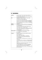
EM64T CPU - Intel® H55 - Dual Channel DDR3 Memory Technology (see CAUTION 4) - 4 x DDR3 DIMM slots - Supports DDR3 2600+(OC)/2133(OC)/1866(OC)/1600/ 1333/1066 non-ECC, un-buffered memory - Max. capacity of system memory: 16GB (see CAUTION 5) - Supports Intel® Extreme Memory Profile (XMP) (see - ASRock H55 Extreme3 | User Manual - Page 7
Audio LAN Rear Panel I/O SATA3 USB 3.0 Connector - 7.1 CH HD Audio with Content Protection - DAC with 110dB dynamic range (VIA® VT2020 Audio Codec) - Supports HDMI Audio with Dolby True HD and DTS HD Master Audio (when Intel® CoreTM i5 600 series / i3 500 series / Pentium® G6950 CPU is installed) - - ASRock H55 Extreme3 | User Manual - Page 8
- CPU VID, VCCM, SB, VTT, PCH PLL Voltage Multi-adjustment - Supports I. O. T. (Intelligent Overclocking Technology) Support CD - Drivers, Utilities, AntiVirus Software (Trial Version), ASRock Software Suite (CyberLink DVD Suite and Creative Sound Blaster X-Fi MB) (OEM and Trial Version - ASRock H55 Extreme3 | User Manual - Page 9
the setting in the BIOS, applying Untied Overclocking Technology motherboard supports Dual Channel Memory Technology. Before you implement Dual Channel Memory Technology, make sure to read the installation guide ASRock OC Tuner. ASRock website: http://www.asrock.com/feature/OCTuner/index.htm 9 - ASRock H55 Extreme3 | User Manual - Page 10
POST or press key to BIOS setup menu to access ASRock Instant Flash. Just launch this tool and save the new BIOS file to your USB flash drive, 1.00W in off mode condition. To meet EuP standard, an EuP ready motherboard and an EuP ready power supply are required. According to Intel's suggestion, - ASRock H55 Extreme3 | User Manual - Page 11
Motherboard Layout 2.0 USB 3.0 SATA3 6Gb/s 40 PCIE1 H55 Extreme3 39 FRESCO FL1000G PCIE2 RoHS SATA3_1_2 SATAII_4_5 SATAII_2_3 H55 Marvell 9123/ 9120 clr CMOS AUDIO CODEC HD_AUDIO1 1 HDMI_SPDIF1 1 COM1 1 PCI2 PCI3 CHA_FAN3 1 IR1 FRONT_1394 1 VIA VT6308S 1394a CMOS 64Mb BIOS - ASRock H55 Extreme3 | User Manual - Page 12
1.4 I/O Panel 1 2 34 58 69 7 10 17 16 1 USB 2.0 Ports (USB01) 2 VGA/D-Sub Port 3 USB 2.0 Ports (USB23) * 4 LAN RJ-45 Port 5 Central / Bass (Orange) 6 Rear Speaker (Black) 7 Optical SPDIF Out Port 8 Line In (Light Blue) ** 9 Front Speaker (Lime) 15 14 13 12 11 10 Microphone (Pink) 11 USB - ASRock H55 Extreme3 | User Manual - Page 13
cable to the front panel audio header. After restarting your computer, you will find "VIA HD Audio Deck" tool on your system. Please follow below instructions according to the OS you install. For Windows® XP / XP 64-bit OS: Please click "VIA HD Audio Deck" icon. Click "Jack" and then click - ASRock H55 Extreme3 | User Manual - Page 14
settings. 1. Unplug the power cord from the wall socket before touching any component. 2. To avoid damaging the motherboard components due to static electricity, NEVER place your motherboard directly on the carpet or the like. Also remember to use a grounded wrist strap or touch a safety grounded - ASRock H55 Extreme3 | User Manual - Page 15
). 1. It is recommended to use the cap tab to handle and avoid kicking off the PnP cap. 2. This cap must be placed if returning the motherboard for after service. 15 - ASRock H55 Extreme3 | User Manual - Page 16
Step 3. Insert the 1156-Pin CPU: Step 3-1. Hold the CPU by the edge where is marked with black line. black line Step 3-2. Orient the CPU with IHS (Integrated Heat Sink) up. Locate Pin1 and the two orientation key notches. orientation key notch alignment key Pin1 Pin1 orientation key notch 1156 - ASRock H55 Extreme3 | User Manual - Page 17
11, No. 3). For proper installation, please kindly refer to the instruction manuals of your CPU fan and heatsink. Below is an example to illustrate or contact other components. Please be noticed that this motherboard supports Combo Cooler Option (C.C.O.), which provides the flexible option to - ASRock H55 Extreme3 | User Manual - Page 18
2.5 Installation of Memory Modules (DIMM) This motherboard provides four 240-pin DDR3 (Double Data Rate 3) DIMM slots, and supports Dual Channel Memory Technology. For dual channel configuration, you always need to install identical (the same brand, speed, size and chiptype) DDR3 DIMM pair in - ASRock H55 Extreme3 | User Manual - Page 19
matches the break on the slot. notch break notch break The DIMM only fits in one correct orientation. It will cause permanent damage to the motherboard and the DIMM if you force the DIMM into the slot at incorrect orientation. Step 3. Firmly insert the DIMM into the slot until the retaining - ASRock H55 Extreme3 | User Manual - Page 20
the expansion card and make necessary hardware settings for the card before you start the installation. Step 2. Remove the system unit cover (if your motherboard is already installed in a chassis). Step 3. Remove the bracket facing the slot that you intend to use. Keep the screws for later use. Step - ASRock H55 Extreme3 | User Manual - Page 21
and pin3 on CLRCMOS1 for 5 seconds. However, please do not clear the CMOS right after you update the BIOS. If you need to clear the CMOS when you just finish updating the BIOS, you must boot up the system first, and then shut it down before you do the clear-CMOS action - ASRock H55 Extreme3 | User Manual - Page 22
detected. Please adjust the BIOS option "Clear Status" to power supply These two Serial ATA3 (SATA3) connectors support SATA data cables for internal storage devices. The current SATA3 hard disk or the SATAII / SATA3 connector on this motherboard. Please connect the black end of SATA power cable to - ASRock H55 Extreme3 | User Manual - Page 23
panel, there are three USB 2.0 headers on this motherboard. Each USB 2.0 header can support two USB 2.0 ports. Infrared Module Header (5-pin supports Jack Sensing, but the panel wire on the chassis must support HDA to function correctly. Please follow the instruction in our manual and chassis manual - ASRock H55 Extreme3 | User Manual - Page 24
E. Enter BIOS Setup Utility. Enter Advanced Settings, and then select Chipset Configuration. Set the Front Panel Control option from [Auto] to [Enabled]. System Panel Header (9-pin PANEL1) ( - ASRock H55 Extreme3 | User Manual - Page 25
provides 4-Pin CPU fan (Quiet Fan) support, the 3-Pin CPU fan still can work successfully even without the fan speed control function. If you plan to connect the 3-Pin CPU fan to the CPU fan connector on this motherboard, please connect it to Pin 1-3. Pin 1-3 Connected 3-Pin Fan Installation - ASRock H55 Extreme3 | User Manual - Page 26
the HDMI_SPDIF connector of HDMI VGA card to this header. Please connect the black end (A) of HDMI_SPDIF cable to the HDMI_SPDIF header on the motherboard. Then connect the white end (B or C) of HDMI_SPDIF cable to the HDMI_SPDIF connector of HDMI VGA card. A. black end +5V SPDIFOUT GND B. white - ASRock H55 Extreme3 | User Manual - Page 27
2.9 Smart Switches This motherboard has three smart switches: power switch, reset switch and clear CMOS switch, allowing users to quickly turn on/off or reset the system or clear - ASRock H55 Extreme3 | User Manual - Page 28
Dr. Debug is used to provide code information, which makes troubleshooting even easier. Please see the diagrams below for reading the in memory. Store the Uncompressed pointer for future use in PMM. Copying Main BIOS into memory. Leaves all RAM below 1MB Read-Write including E000 and F000 shadow - ASRock H55 Extreme3 | User Manual - Page 29
POST, Runtime data area. Also initialize BIOS modules on POST entry and GPNV area. Initialized CMOS as mentioned in the Kernel Variable "wCMOSFlags." Check CMOS diagnostic byte to determine if battery power is OK and CMOS checksum is OK. Verify CMOS checksum manually by reading storage area. If the - ASRock H55 Extreme3 | User Manual - Page 30
85 Display errors to the user and gets the user response for error. 87 Execute BIOS setup if needed / requested. 8C Late POST initialization of chipset registers. 8D Build ACPI tables (if ACPI is supported) 8E Program the peripheral parameters. Enable/Disable NMI as selected 90 Late POST - ASRock H55 Extreme3 | User Manual - Page 31
motherboard with a HDMI_SPDIF header. This motherboard motherboard. For the proper installation of HDMI VGA card, please refer to the installation guide manual of HDMI VGA card vendor. Incorrect connection may cause permanent damage to this motherboard Otherwise, the motherboard and the user manual for - ASRock H55 Extreme3 | User Manual - Page 32
ATAII (SATAII) Hard Disks Installation This motherboard adopts Intel® H55 chipset that supports Serial ATA (SATA) / Serial ATAII (SATAII) hard disks. You may install SATA / SATAII hard disks on this motherboard for internal storage devices. This section will guide you to install the SATA / SATAII - ASRock H55 Extreme3 | User Manual - Page 33
2.14 Hot Plug Function for SATA / SATAII HDDs This motherboard supports Hot Plug function for SATA / SATAII in AHCI mode. Intel® H55 chipset provides hardware support for Advanced Host controller Interface (AHCI), a new programming interface for SATA host controllers developed thru a joint industry - ASRock H55 Extreme3 | User Manual - Page 34
installed into system properly. The latest SATA / SATAII / SATA3 driver is available on our support website: www.asrock.com 4. Make sure to use the SATA power cable & data cable, which are from our motherboard package. 5. Please follow below instructions step by step to reduce the risk of HDD crash - ASRock H55 Extreme3 | User Manual - Page 35
cable to (White) to the power supply 1x4-pin cable. the motherboard's SATAII / SATA3 connector. SATA power cable 1x4-pin power connector ( of attention, before you process the Hot Unplug: Please do follow below instruction sequence to process the Hot Unplug, improper procedure will cause the SATA - ASRock H55 Extreme3 | User Manual - Page 36
Driver Installation Guide To install the drivers to your system, please insert the support CD to your optical drive first. Then, the drivers compatible to your system can be auto-detected and listed on the support CD driver ) STEP 1: Set Up BIOS. A. Enter BIOS SETUP UTILITY Advanced screen Storage - ASRock H55 Extreme3 | User Manual - Page 37
Technology This motherboard supports Untied Overclocking Technology, which means during overclocking, FSB enjoys better margin due to fixed PCI / PCIE buses. Before you enable Untied Overclocking function, please enter "Overclock Mode" option of BIOS setup to set the selection from [Auto] to [Manual - ASRock H55 Extreme3 | User Manual - Page 38
SETUP UTILITY 3.1 Introduction This section explains how to use the BIOS SETUP UTILITY to configure your system. The BIOS FWH chip on the motherboard stores the BIOS SETUP UTILITY. You may run the BIOS SETUP UTILITY when you start up the computer. Please press or during the Power-On-Self - ASRock H55 Extreme3 | User Manual - Page 39
Main OC Tweaker Advanced H/W Monitor Boot Security Exit System Overview System Time System Date [14:00:09] [Mon 02/22/2010] BIOS Version : H55 Extreme3 P1.00 Processor Type : Intel (R) Core (TM) i5 CPU 670 @ 3.47GHz (64bit) Processor Speed : 3466MHz Microcode Update : 20652/9 Cache Size - ASRock H55 Extreme3 | User Manual - Page 40
setting. Please note that overclocing may cause damage to your CPU and motherboard. It should be done at your own risk and expense. Load Memory to enable this function, please set this item to [Enabled]. Besides the BIOS option, you can also choose our Intelligent Energy Saver utility to enable this - ASRock H55 Extreme3 | User Manual - Page 41
options: [Auto], [Manual], [I.O.T.] and [Optimized]. The default value is [Auto]. If you select [Manual], Untied Overclocking function is find this item appear to allow you changing the ratio value of this motherboard. IGD Frequency Use this option to adjust IGD frequency. QPI Frequency Use this - ASRock H55 Extreme3 | User Manual - Page 42
Timing Control DRAM tCL DRAM tRCD DRAM tRP DRAM tRAS DRAM tRFC DRAM tWR DRAM tWTR DRAM tRRD DRAM tRTP DRAM tFAW DRAM Command Rate BIOS SETUP UTILITY 9 [Auto] 9 [Auto] 9 [Auto] 24 [Auto] 74 [Auto] 10 [Auto] 5 [Auto] 4 [Auto] 5 [Auto] 20 [Auto] [Auto] DRAM tCL Min = 6 Max = 11 +F1 F9 F10 - ASRock H55 Extreme3 | User Manual - Page 43
VDroop Control Use this to enable or disable ASRock VDroop control. Configuration options: [With VDroop] and [Without VDroop]. The default value is [With VDroop]. CPU Voltage Use this to select CPU Voltage. Configuration options: [Auto], [Manual] and [Overdrive Offset]. The default value is [Auto - ASRock H55 Extreme3 | User Manual - Page 44
cause system to malfunction. CPU Configuration Chipset Configuration ACPI Configuration Storage Configuration PCIPnP Configuration SuperIO Configuration USB Configuration BIOS Update Utility ASRock Instant Flash Select Screen Select Item Enter Go to Sub Screen F1 General Help F9 Load Defaults F10 - ASRock H55 Extreme3 | User Manual - Page 45
3.4.1CPU Configuration BIOS SETUP UTILITY Advanced Configure advanded CPU settings Intel (R) Core this motherboard. Enhance Halt State All processors support the Halt State (C1). The C1 state is supported through the native processor instructions HLT and MWAIT and requires no hardware support - ASRock H55 Extreme3 | User Manual - Page 46
® VistaTM and want to enable this function, please set this item to [Enabled]. This item will be hidden if the current CPU does not support Intel (R) SpeedStep(tm) tech.. Please note that enabling this function may reduce CPU voltage and lead to system stability or compatibility issue with some - ASRock H55 Extreme3 | User Manual - Page 47
3.4.2Chipset Configuration BIOS SETUP UTILITY Advanced Chipset Settings Primary Graphics Adapter architecture that offers breakthrough performance for the motherboard through efficient memory utilization. In DVMT mode, the graphics driver allocates memory as needed for running graphics - ASRock H55 Extreme3 | User Manual - Page 48
OnBoard Lan This allows you to enable or disable the "OnBoard Lan" feature. Onboard 1394 This allows you to enable or disable the "Onboard 1394" feature. Intel VT-d Configuration Use this to enable or disable Intel® VT-d technology (Intel® Virtualization Technology for Directed I/O). The default - ASRock H55 Extreme3 | User Manual - Page 49
3.4.3 ACPI Configuration BIOS SETUP UTILITY Advanced ACPI the Suspend-toRAM feature. Select [Auto] will enable this feature if the OS supports it. Check Ready Bit Use this item to enable or disable the feature Check you plan to use this motherboard to submit Windows® VistaTM certification. 49 - ASRock H55 Extreme3 | User Manual - Page 50
3.4.4 Storage Configuration BIOS SETUP UTILITY Advanced Storage Configuration SATA Operation Mode SATAII 1,2,3,4 Plug" and "Link Power Management" will appear. AHCI (Advanced Host Controller Interface) supports NCQ and other new features that will improve SATA disk performance but IDE mode does - ASRock H55 Extreme3 | User Manual - Page 51
BIOS SETUP UTILITY Advanced SATAII 1 Master Device Vendor Size LBA Mode Block Mode PIO Mode Async DMA Ultra DMA S.M.A.R.T. Type LBA/Large Mode Block (Multi-Sector Transfer) PIO Mode DMA Mode S.M.A.R.T. 32Bit Data Transfer :Hard Disk :ST340014A :40.0 GB :Supported :16Sectors :4 :MultiWord DMA-2 : - ASRock H55 Extreme3 | User Manual - Page 52
Enabled]. 32-Bit Data Transfer Use this item to enable 32-bit access to maximize the IDE hard disk data transfer rate. 3.4.5PCIPnP Configuration BIOS SETUP UTILITY Advanced Advanced PCI / PnP Settings PCI Latency Timer PCI IDE BusMaster [64] [Enabled] Value in units of PCI clocks for PCI device - ASRock H55 Extreme3 | User Manual - Page 53
3.4.6 Super IO Configuration BIOS SETUP UTILITY Advanced Configure Super IO Chipset Serial Port Address Infrared Port Address PS/2 Port Type [3F8 / IRQ4] [Disabled] [Auto] +F1 F9 F10 ESC Select - ASRock H55 Extreme3 | User Manual - Page 54
you have USB compatibility issue, it is recommended to select [Disabled] to enter OS. [BIOS Setup Only] - USB devices are allowed to use only under BIOS setup and Windows / Linux OS. USB3 port device cannot support USB3 legacy. USB 2.0 Rate Matching hub Use this item to enable or disable the USB - ASRock H55 Extreme3 | User Manual - Page 55
of the CPU temperature, motherboard temperature, CPU fan speed, chassis fan speed, and the critical voltage. BIOS SETUP UTILITY Main OC you to set the chassis fan 3 speed. Configuration options: [Full On] and [Manual mode]. The default is value [Full On]. Case Open Feature This allows you to enable - ASRock H55 Extreme3 | User Manual - Page 56
F1 General Help F9 Load Defaults F10 Save and Exit ESC Exit v02.54 (C) Copyright 1985-2005, American Megatrends, Inc. 3.6.1 Boot Settings Configuration BIOS SETUP UTILITY Boot Boot Settings Configuration Full Screen Logo AddOn ROM Display Boot Logo Boot From Onboard LAN Bootup Num-Lock [Enabled - ASRock H55 Extreme3 | User Manual - Page 57
option "Full Screen Logo". Configuration options: [Auto], [EuP], [Scenery] and [ASRock]. The default value is [Auto]. Boot From Onboard LAN Use this item to enable system. For the user password, you may also clear it. BIOS SETUP UTILITY Main OC Tweaker Advanced H/W Monitor Boot Security Exit - ASRock H55 Extreme3 | User Manual - Page 58
. Discard Changes When you select this option, it will pop-out the following message, "Discard changes?" Select [OK] to discard all changes. Load BIOS Defaults Load BIOS default values for all the setup questions. F9 key can be used for this operation. Load Performance Setup Default (IDE/SATA) This - ASRock H55 Extreme3 | User Manual - Page 59
install the necessary drivers to activate the devices. 4.2.3 Utilities Menu The Utilities Menu shows the applications software that the motherboard supports. Click on a specific item then follow the installation wizard to install it. 4.2.4 Contact Information If you need to contact ASRock or want to
-
 1
1 -
 2
2 -
 3
3 -
 4
4 -
 5
5 -
 6
6 -
 7
7 -
8
-
9
-
10
-
11
-
12
-
13
-
14
-
15
-
16
-
17
-
18
-
19
-
20
-
21
-
22
-
23
-
24
-
25
-
26
-
27
-
28
-
29
-
30
-
31
-
32
-
33
-
34
-
35
-
36
-
37
-
38
-
39
-
40
-
41
-
42
-
43
-
44
-
45
-
46
-
47
-
48
-
49
-
50
-
51
-
52
-
53
-
54
-
55
-
56
-
57
-
58
-
59
 |
 |

1
H55 Extreme3
User Manual
Version 1.0
Published February 2010
Copyright©2010 ASRock INC. All rights reserved.