ASRock H55M-GE User Manual
ASRock H55M-GE Manual
 |
View all ASRock H55M-GE manuals
Add to My Manuals
Save this manual to your list of manuals |
ASRock H55M-GE manual content summary:
- ASRock H55M-GE | User Manual - Page 1
H55M-GE User Manual Version 1.0 Published May 2010 Copyright©2010 ASRock INC. All rights reserved. 1 - ASRock H55M-GE | User Manual - Page 2
may appear in this manual. With respect to the contents of this manual, ASRock does not provide warranty of any kind, either expressed or implied, including but CALIFORNIA, USA ONLY The Lithium battery adopted on this motherboard contains Perchlorate, a toxic substance controlled in Perchlorate Best - ASRock H55M-GE | User Manual - Page 3
14 2.4 Installation of Heatsink and CPU fan 16 2.5 Installation of Memory Modules (DIMM 17 2.6 Expansion Slots (PCI and PCI Express Slots 19 2.7 Jumpers Setup 20 2.8 Onboard Headers and Connectors 21 2.9 SATAII Hard Disk Setup Guide 25 2.10 Serial ATA (SATA) / Serial ATAII (SATAII - ASRock H55M-GE | User Manual - Page 4
47 3.6 Boot Screen 48 3.6.1 Boot Settings Configuration 48 3.7 Security Screen 49 3.8 Exit Screen 50 4 Software Support 51 4.1 Install Operating System 51 4.2 Support CD Information 51 4.2.1 Running Support CD 51 4.2.2 Drivers Menu 51 4.2.3 Utilities Menu 51 4.2.4 Contact Information 51 4 - ASRock H55M-GE | User Manual - Page 5
guide to BIOS setup and information of the Support CD. Because the motherboard specifications and the BIOS software might be updated, the content of this manual will be subject to change without notice. In case any modifications of this manual occur, the updated version will be available on ASRock - ASRock H55M-GE | User Manual - Page 6
1.2 Specifications Platform CPU Chipset Memory Expansion Slot Graphics * Audio - Micro ATX Form Factor: 9.6-in x 8.7-in, 24.4 cm x 22.1 cm - All Solid Capacitor design (100% Japan-made high-quality Conductive Polymer Capacitors) (H55M-GE R2.0) - Supports Intel® CoreTM i7 / i5 / i3 and Pentium® - ASRock H55M-GE | User Manual - Page 7
audio connector - 3 x USB 2.0 headers (support 6 USB 2.0 ports) (see CAUTION 11) - 16Mb AMI Legal BIOS - Supports "Plug and Play" - ACPI 1.1 Compliance Wake Up Events - Supports jumperfree - SMBIOS 2.3.1 Support - CPU VID, CPU GFX, VCCM, VTT, PCH PLL Voltage Multi-adjustment - Drivers, Utilities - ASRock H55M-GE | User Manual - Page 8
12V, +5V, +3.3V, CPU Vcore OS - Microsoft® Windows® 7 / 7 64-bit asrock.com WARNING Please realize that there is a certain risk involved with overclocking, including adjusting the setting in the BIOS, applying Untied Overclocking Technology, or using the thirdparty overclocking tools. Overclocking - ASRock H55M-GE | User Manual - Page 9
This motherboard supports Untied Overclocking Technology. Please read "Untied Overclocking Technology" on page 30 for details. 4. This motherboard supports Dual Channel Memory Technology. Before you implement Dual Channel Memory Technology, make sure to read the installation guide of memory modules - ASRock H55M-GE | User Manual - Page 10
MS-DOS or Windows®. With this utility, you can press key during the POST or press key to BIOS setup menu to access ASRock Instant Flash. Just launch this tool and save the new BIOS file to your USB flash drive, floppy disk or hard drive, then you can update your BIOS only in a few - ASRock H55M-GE | User Manual - Page 11
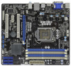
33 32 USB 2.0 T: USB2 B: USB3 USB 2.0 T: USB0 B: USB1 Top: RJ-45 Top: LINE IN Center: FRONT Bottom: MIC IN LAN PHY 1 HD_AUDIO1 RoHS AUDIO CODEC Super I/O COM1 1 LPT1 1 CHA_FAN1 H55M-GE PCI Express 1156-Pin CPU Socket 24 USB 2.0 Header (USB8_9, Blue) 7 2 x 240-pin DDR3 DIMM Slots 25 USB - ASRock H55M-GE | User Manual - Page 12
1.4 I/O Panel 1 2 3 4 5 6 11 10 1 USB 2.0 Ports (USB45) 2 VGA/D-Sub Port 3 LAN RJ-45 Port 4 Line In (Light Blue) 5 Front Speaker (Lime) 6 Microphone (Pink) 9 8 7 7 USB 2.0 Ports (USB01) 8 USB 2.0 Ports (USB23) 9 HDMI Port 10 VGA/DVI-D Port 11 PS/2 Keyboard Port (Purple) * There are two - ASRock H55M-GE | User Manual - Page 13
Precautions Take note of the following precautions before you install motherboard components or change any motherboard settings. 1. Unplug the power cord from the wall socket before touching any component. 2. To avoid damaging the motherboard components due to static electricity, NEVER place your - ASRock H55M-GE | User Manual - Page 14
Socket Body 1156-Pin Socket Overview Before you insert the 1156-Pin CPU into the socket, please check if the CPU surface is unclean or if there is any bent pin on the socket. Do not force to insert the CPU into the socket 2. This cap must be placed if returning the motherboard for after service. 14 - ASRock H55M-GE | User Manual - Page 15
key Pin1 Pin1 orientation key notch 1156-Pin CPU alignment key 1156-Pin Socket For proper inserting, please ensure to match the two orientation key notches of the CPU with the two alignment keys of the socket. Step 3-3. Carefully place the CPU into the socket by using a purely vertical motion - ASRock H55M-GE | User Manual - Page 16
with fan operation or contact other components. Please be noticed that this motherboard supports Combo Cooler Option (C.C.O.), which provides the flexible option to adopt two different CPU cooler types, Socket LGA 775 and LGA 1156. The white throughholes are for Socket LGA 1156 CPU fan. 16 - ASRock H55M-GE | User Manual - Page 17
2.5 Installation of Memory Modules (DIMM) This motherboard provides four 240-pin DDR3 (Double Data Rate 3) DIMM slots, and supports Dual Channel Memory Technology. For dual channel configuration, you always need to install identical (the same brand, speed, size and chiptype) DDR3 DIMM pair in the - ASRock H55M-GE | User Manual - Page 18
matches the break on the slot. notch break notch break The DIMM only fits in one correct orientation. It will cause permanent damage to the motherboard and the DIMM if you force the DIMM into the slot at incorrect orientation. Step 3. Firmly insert the DIMM into the slot until the retaining - ASRock H55M-GE | User Manual - Page 19
2.6 Expansion Slots (PCI and PCI Express Slots) There are 2 PCI slots and 2 PCI Express slots on this motherboard. PCI slot: PCI slot is used to install expansion cards that have the 32-bit PCI interface. PCIE slots: PCIE1 (PCIE x16 slot; Blue) is used for PCI Express x16 lane width graphics cards. - ASRock H55M-GE | User Manual - Page 20
current provided by power supply. When you select +5V_DUAL, USB devices can wake up the system under S3 (Suspend to RAM) state. USB_PWR3 (see p.11, No. 26) clear the CMOS right after you update the BIOS. If you need to clear the CMOS when you just finish updating the BIOS, you must boot up the - ASRock H55M-GE | User Manual - Page 21
the BIOS option p.11 No. 22) USB_PWR P-11 P+11 GND DUMMY 1 GND P+10 P-10 USB_PWR USB_PWR P-9 P+9 GND DUMMY 1 GND P+8 P-8 USB_PWR USB_PWR P-7 motherboard. Besides six default USB 2.0 ports on the I/O panel, there are three USB 2.0 headers on this motherboard. Each USB 2.0 header can support two USB - ASRock H55M-GE | User Manual - Page 22
supports an optional wireless transmitting and receiving infrared module. This motherboard supports audio devices. 1. High Definition Audio supports Jack Sensing, but the panel wire on the chassis must support HDA to function correctly. Please follow the instruction in our manual and chassis manual - ASRock H55M-GE | User Manual - Page 23
audio panel only. You don't need to connect them for AC'97 audio 10) motherboard provides 4-Pin CPU fan (Quiet Fan) support, the 3-Pin CPU fan still can work successfully even without the fan speed control function. If you plan to connect the 3-Pin CPU fan to the CPU fan connector on this motherboard - ASRock H55M-GE | User Manual - Page 24
Though this motherboard provides 24-pin ATX power connector, 12 24 it can still work to this connector. This COM1 header supports a serial port module. HDMI_SPDIF header, providing SPDIF audio output to HDMI VGA card, allows the system to connect HDMI Digital TV/ projector/LCD devices. Please - ASRock H55M-GE | User Manual - Page 25
guide. Some default setting of SATAII hard disks may not be at SATAII mode, which operate with the best performance. In order to enable SATAII function, please follow the below instruction website for details: http://www.hitachigst.com/hdd/support/download.htm The above examples are just for your - ASRock H55M-GE | User Manual - Page 26
(SATAII) Hard Disks Installation This motherboard adopts Intel® H55 bridge chipset that supports Serial ATA (SATA) / Serial ATAII (SATAII) hard disks. You may install SATA / SATAII hard disks on this motherboard for internal storage devices. This section will guide you to install the SATA / SATAII - ASRock H55M-GE | User Manual - Page 27
is installed into system properly. The latest SATA / SATAII driver is available on our support website: www.asrock.com 4. Make sure to use the SATA power cable & data cable, which are from our motherboard package. 5. Please follow below instructions step by step to reduce the risk of HDD crash or - ASRock H55M-GE | User Manual - Page 28
cable to (White) to the power supply 1x4-pin cable. the motherboard's SATAII connector. SATA power cable 1x4-pin power connector (White) attention, before you process the Hot Unplug: Please do follow below instruction sequence to process the Hot Unplug, improper procedure will cause the SATA - ASRock H55M-GE | User Manual - Page 29
to your system can be auto-detected and listed on the support CD driver page. Please follow the order from up to bottom side to install those required drivers. Therefore, the drivers you install can work properly. 2.14 Installing Windows® 7 / 7 64-bit / VistaTM / VistaTM 64-bit / XP / XP 64-bit If - ASRock H55M-GE | User Manual - Page 30
Technology This motherboard supports Untied Overclocking Technology, which means during overclocking, FSB enjoys better margin due to fixed PCI / PCIE buses. Before you enable Untied Overclocking function, please enter "Overclock Mode" option of BIOS setup to set the selection from [Auto] to [Manual - ASRock H55M-GE | User Manual - Page 31
off and then back on. Because the BIOS software is constantly being updated, the following BIOS setup screens and descriptions are for reference purpose : Main To set up the system time/date information OC Tweaker To set up overclocking features Advanced To set up the advanced BIOS features - ASRock H55M-GE | User Manual - Page 32
Time System Date [14:00:09] [Fri 05/14/2010] BIOS Version : H55M-GE P1.00 Processor Type : Intel (R) Core (TM) i5 CPU K 655 @ 3.20GHz (64bit) Processor Speed : 3200MHz Microcode Update : 20655/2 Cache Size : 4096KB Total Memory DDR3_A2 DDR3_A1 DDR3_B2 DDR3_B1 : 1024MB with 128MB shared - ASRock H55M-GE | User Manual - Page 33
overclocking features. BIOS SETUP UTILITY Main OC Tweaker Advanced H/W Monitor Boot Security Exit OC Tweaker Settings Turbo 50 [Press Enter] Load CPU EZ OC Setting [Press Enter] Load Memory [Auto] CPU Ratio Setting 24[24] Overclocking may cause damage to your CPU and motherboard. It should - ASRock H55M-GE | User Manual - Page 34
in S1, S3 and S4 state. The default value is [Disabled]. Overclock Mode Use this to select Overclock Mode. Configuration options: [Auto], [Manual] and [Optimized]. The default value is [Auto]. If you select [Manual], Untied Overclocking function is enabled. Please refer to page 30 for the details of - ASRock H55M-GE | User Manual - Page 35
DRAM tRCD DRAM tRP DRAM tRAS DRAM tRFC DRAM tWR DRAM tWTR DRAM tRRD DRAM tRTP DRAM tFAW DRAM Command Rate BIOS SETUP UTILITY 9 [Auto] 9 [Auto] 9 [Auto] 24 [Auto] 74 [Auto] 10 [Auto] 5 [Auto] 4 [Auto] 5 [Auto] 20 [Auto] [Auto] DRAM tCL Min = 6 Max = 11 +F1 F9 F10 ESC Select Screen Select Item - ASRock H55M-GE | User Manual - Page 36
[1] to [63]. DRAM Command Rate Use this item to adjust DRAM Command Rate. Configuration options : [Auto], [1] and [2]. CPU Voltage Use this to select CPU Voltage. Configuration options: [Auto], [Manual] and [Overdrive Offset]. The default value is [Auto]. DRAM Voltage Use this to select DRAM Voltage - ASRock H55M-GE | User Manual - Page 37
. ASRock Instant Flash ASRock Instant Flash is a BIOS flash utility embedded in Flash ROM. This convenient BIOS update tool allows you to update system BIOS without entering operating systems first like MS-DOS or Windows®. Just launch this tool and save the new BIOS file to your USB flash - ASRock H55M-GE | User Manual - Page 38
Megatrends, Inc. CPU Ratio Setting If the ratio status is unlocked, you will find this item appear to allow you changing the ratio value of this motherboard. Enhance Halt State All processors support the Halt State (C1). The C1 state is supported through the native processor instructions HLT and - ASRock H55M-GE | User Manual - Page 39
Schemes" as "Portable/Laptop" to enable this function. If you install Windows® VistaTM / 7 and want to enable this function, please set this item to [Enabled]. This item will be hidden if the current CPU does not support Intel (R) SpeedStep(tm) tech.. Please note that enabling this function may - ASRock H55M-GE | User Manual - Page 40
3.4.2Chipset Configuration BIOS SETUP UTILITY Advanced Chipset Settings Primary Graphics Adapter Share Memory DVMT Mode Select DVMT/FIXED Memory Onboard HD Audio Front Panel Onboard HDMI HD Audio OnBoard Lan [PCI] [Auto] [DVMT Mode] [Maximum DVMT] [Auto] [Auto] [Enabled] [Enabled] Intel VT-d - ASRock H55M-GE | User Manual - Page 41
]. 3.4.3 ACPI Configuration BIOS SETUP UTILITY Advanced ACPI Configuration Suspend To RAM Restore on AC/Power Loss Ring-In Power On PCI Devices Power On PS Suspend-toRAM feature. Select [Auto] will enable this feature if the OS supports it. Check Ready Bit Use this item to enable or disable the - ASRock H55M-GE | User Manual - Page 42
to use this motherboard to submit Windows® VistaTM certification. 3.4.4 Storage Configuration BIOS SETUP UTILITY Advanced Storage and "Link Power Management" will appear. AHCI (Advanced Host Controller Interface) supports NCQ and other new features that will improve SATA disk performance but IDE - ASRock H55M-GE | User Manual - Page 43
" as the example in the following instruction. BIOS SETUP UTILITY Advanced Primary IDE Master Device :ST340014A :40.0 GB :Supported :16Sectors :4 :MultiWord DMA-2 :Ultra DMA-5 :Supported [Auto] [Auto] [ for a hard disk > 512 MB under DOS and Windows; for Netware and UNIX user, select [Disabled] to - ASRock H55M-GE | User Manual - Page 44
access to maximize the IDE hard disk data transfer rate. 3.4.5PCIPnP Configuration BIOS SETUP UTILITY Advanced Advanced PCI / PnP Settings PCI Latency Timer PCI IDE BusMaster [64] [Enabled] Value in units of PCI clocks for PCI device latency timer register. +F1 F9 F10 ESC Select Screen Select - ASRock H55M-GE | User Manual - Page 45
3.4.6 Super IO Configuration BIOS SETUP UTILITY Advanced Configure Super IO Chipset Serial Port Address Infrared Port Address Parallel Port Address Parallel Port Mode EPP Version ECP Mode DMA Channel - ASRock H55M-GE | User Manual - Page 46
Use this item to enable or disable the use of USB controller. Legacy USB Support Use this option to select legacy support for USB devices. There are four configuration options: [Enabled], [Auto], [Disabled] and [BIOS Setup Only]. The default value is [Enabled]. Please refer to below descriptions - ASRock H55M-GE | User Manual - Page 47
to monitor the status of the hardware on your system, including the parameters of the CPU temperature, motherboard temperature, CPU fan speed, chassis fan speed, and the critical voltage. BIOS SETUP UTILITY Main OC Tweaker Advanced H/W Monitor Boot Security Exit Hardware Health Event Monitoring - ASRock H55M-GE | User Manual - Page 48
section, it will display the available devices on your system for you to configure the boot settings and the boot priority. BIOS SETUP UTILITY Main OC Tweaker Advanced H/W Monitor Boot Security Exit Boot Settings Boot Settings Configuration Configure Settings during System Boot. 1st Boot Device - ASRock H55M-GE | User Manual - Page 49
the option "Full Screen Logo". Configuration options: [Auto], [EuP], [Scenery] and [ASRock]. The default value is [Auto]. Boot From Onboard LAN Use this item to enable For the user password, you may also clear it. BIOS SETUP UTILITY Main OC Tweaker Advanced H/W Monitor Boot Security Exit Security - ASRock H55M-GE | User Manual - Page 50
3.8 Exit Screen BIOS SETUP UTILITY Main OC Tweaker Advanced H/W Monitor Boot Security Exit Exit Options Save Changes and Exit Discard Changes and Exit Discard Changes Load BIOS Defaults Load Performance Setup Default (IDE/SATA) Load Performance Setup AHCI Mode Load Power Saving Setup Default Exit - ASRock H55M-GE | User Manual - Page 51
CD that came with the motherboard contains necessary drivers and useful utilities that enhance the motherboard features. 4.2.1 Running The Support CD To begin using the support CD, insert the CD into your CD-ROM drive. The CD automatically displays the Main Menu if "AUTORUN" is enabled in your
-
 1
1 -
 2
2 -
 3
3 -
 4
4 -
 5
5 -
 6
6 -
 7
7 -
8
-
9
-
10
-
11
-
12
-
13
-
14
-
15
-
16
-
17
-
18
-
19
-
20
-
21
-
22
-
23
-
24
-
25
-
26
-
27
-
28
-
29
-
30
-
31
-
32
-
33
-
34
-
35
-
36
-
37
-
38
-
39
-
40
-
41
-
42
-
43
-
44
-
45
-
46
-
47
-
48
-
49
-
50
-
51
 |
 |

1
H55M-GE
User Manual
Version 1.0
Published May 2010
Copyright©2010 ASRock INC. All rights reserved.