ASRock H55M-LE User Manual
ASRock H55M-LE Manual
 |
View all ASRock H55M-LE manuals
Add to My Manuals
Save this manual to your list of manuals |
ASRock H55M-LE manual content summary:
- ASRock H55M-LE | User Manual - Page 1
H55M-LE User Manual Version 1.0 Published January 2010 Copyright©2010 ASRock INC. All rights reserved. 1 - ASRock H55M-LE | User Manual - Page 2
without written consent of ASRock Inc. Products and corporate names appearing in this manual may or may not be intent to infringe. Disclaimer: Specifications and information contained in this manual are furnished for informational use battery adopted on this motherboard contains Perchlorate, a toxic - ASRock H55M-LE | User Manual - Page 3
Guide 28 2.14 Driver Installation Guide 30 2.15 Installing Windows® 7 / 7 64-bit / VistaTM / VistaTM 64-bit / XP / XP 64-bit 30 2.15.1 Installing Windows® XP / XP 64-bit 30 2.15.2 Installing Windows® 7 / 7 64-bit / VistaTM / VistaTM 64-bit 30 2.16 Untied Overclocking Technology 31 3 BIOS - ASRock H55M-LE | User Manual - Page 4
48 3.6 Boot Screen 49 3.6.1 Boot Settings Configuration 49 3.7 Security Screen 50 3.8 Exit Screen 51 4 Software Support 52 4.1 Install Operating System 52 4.2 Support CD Information 52 4.2.1 Running Support CD 52 4.2.2 Drivers Menu 52 4.2.3 Utilities Menu 52 4.2.4 Contact Information 52 4 - ASRock H55M-LE | User Manual - Page 5
guide to BIOS setup and information of the Support CD. Because the motherboard specifications and the BIOS software might be updated, the content of this manual will be subject to change without notice. In case any modifications of this manual occur, the updated version will be available on ASRock - ASRock H55M-LE | User Manual - Page 6
1.2 Specifications Platform CPU Chipset Memory Expansion Slot Graphics * Audio LAN - Micro ATX Form Factor: 9.6-in x 8.0-in, 24.4 cm x 20.3 cm - Solid Capacitor for CPU power - Supports Intel® CoreTM i7 / i5 / i3 and Pentium® G6950 Processors in LGA1156 Package - Supports Intel® Turbo Boost - ASRock H55M-LE | User Manual - Page 7
10) - 16Mb AMI Legal BIOS - Supports "Plug and Play" - ACPI 1.1 Compliance Wake Up Events - Supports jumperfree - SMBIOS 2.3.1 Support - CPU, DRAM, VTT, PCH, CPU PLL, GFX Voltage Multi-adjustment - Drivers, Utilities, AntiVirus Software (Trial Version), ASRock Software Suite (CyberLink DVD Suite - ASRock H55M-LE | User Manual - Page 8
Overclocking (Requires a Processor with Intel® Graphics Technology) Hardware - CPU Temperature Sensing Monitor - Chassis Temperature Sensing - CPU/Chassis/Power Fan Tachometer - CPU Quiet Fan - CPU 3V, CPU Vcore OS - Microsoft® Windows® 7 / 7 64-bit / VistaTM / VistaTM 64-bit / XP / XP 64- - ASRock H55M-LE | User Manual - Page 9
/ XP. For Windows® OS with 64-bit CPU, there is no such limitation. 6. For those CPU that only support up to DDR3 1333, the XMP DDR3 1600 is supported through overclocking. 7. The maximum shared memory size is defined by the chipset vendor and is subject to change. Please check Intel® website - ASRock H55M-LE | User Manual - Page 10
embedded in Flash ROM. This convenient BIOS update tool allows you to update system BIOS without entering operating systems first like MS-DOS or Windows®. With this utility, you can press key during the POST or press key to BIOS setup menu to access ASRock Instant Flash. Just launch this - ASRock H55M-LE | User Manual - Page 11
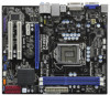
-LE PCI Express 2.0 PCIE1 EuP Ready DDR3 2600+ Gigabit LAN AUDIO CODEC Super I/O COM1 1 LPT1 1 PCIE2 RoHS PCI1 CI1 1 IR1 1 PCI2 CMOS Battery Intel 16Mb H55 BIOS SATAII_2 USB_PWR1 (PORT 6-9) 1 USB8_9 USB6_7 1 1 SATAII_4 CLRCMOS1 1 CHA_FAN1 PANEL1 PLED PWRBTN 1 HDLED RESET - ASRock H55M-LE | User Manual - Page 12
next to the LAN port. Please refer to the table below for the LAN port LED indications. LAN Port LED Indications connection details in accordance with the type of speaker you use. TABLE for Audio Output Connection Audio Output Channels Front Speaker Rear Speaker Central / Bass Side Speaker (No. - ASRock H55M-LE | User Manual - Page 13
. After restarting your computer, you will find "VIA HD Audio Deck" tool on your system. Please follow below instructions according to the OS you install. For Windows® XP / XP 64-bit OS: Please click "VIA HD Audio Deck" icon. Click "Jack" and then click "Configuration". In "Configuration" screen - ASRock H55M-LE | User Manual - Page 14
Precautions Take note of the following precautions before you install motherboard components or change any motherboard settings. 1. Unplug the power cord from the wall socket before touching any component. 2. To avoid damaging the motherboard components due to static electricity, NEVER place your - ASRock H55M-LE | User Manual - Page 15
Intel 1156-Pin CPU, please follow the steps below. Load Plate Load Lever Contact Array Socket Body 1156-Pin Socket Overview Before you insert the 1156-Pin CPU into the socket, please check if the CPU surface is unclean or if there is any bent pin on the socket motherboard for after service. 15 - ASRock H55M-LE | User Manual - Page 16
key Pin1 Pin1 orientation key notch 1156-Pin CPU alignment key 1156-Pin Socket For proper inserting, please ensure to match the two orientation key notches of the CPU with the two alignment keys of the socket. Step 3-3. Carefully place the CPU into the socket by using a purely vertical motion - ASRock H55M-LE | User Manual - Page 17
Heatsink This motherboard is equipped with 1156-Pin socket that supports Intel 1156-Pin CPU. Please adopt the type of heatsink and cooling fan compliant with Intel 1156-Pin CPU to dissipate heat. Before you installed the heatsink, you need to spray thermal interface material between the CPU and the - ASRock H55M-LE | User Manual - Page 18
2.5 Installation of Memory Modules (DIMM) H55M-LE motherboard provides two 240-pin DDR3 (Double Data Rate 3) DIMM slots, and supports Dual Channel Memory Technology. For dual channel configuration, you always need to install two identical (the same brand, speed, size and chip-type) memory modules - ASRock H55M-LE | User Manual - Page 19
are 2 PCI slots and 2 PCI Express slots on this motherboard. PCI slot: PCI slot is used to install expansion cards that have the 32-bit PCI interface. PCIE slots: PCIE1 (PCIE x16 slot; Blue) is used for PCI Express x16 lane width graphics cards. PCIE2 (PCIE x1 slot; White) is used for PCI Express - ASRock H55M-LE | User Manual - Page 20
clear and reset the system parameters to default setup, please turn off the computer and unplug the power cord from the power supply. After waiting for 15 seconds, use a jumper cap to short pin2 and pin3 on CLRCMOS1 for 5 seconds. However, please do not clear the CMOS right after you update the BIOS - ASRock H55M-LE | User Manual - Page 21
be connected to the SATA / SATAII hard disk or the SATAII connector on this motherboard. Besides six default USB 2.0 ports on the I/O panel, there are two USB 2.0 headers on this motherboard. Each USB 2.0 header can support two USB 2.0 ports. Print Port Header (25-pin LPT1) (see p.11 No. 23) AFD - ASRock H55M-LE | User Manual - Page 22
cable that allows convenient connection and control of audio devices. 1. High Definition Audio supports Jack Sensing, but the panel wire on the chassis must support HDA to function correctly. Please follow the instruction in our manual and chassis manual to install your system. 2. If you use AC - ASRock H55M-LE | User Manual - Page 23
to the ground pin. Though this motherboard provides 4-Pin CPU fan (Quiet Fan) support, the 3-Pin CPU fan still can work successfully even without the fan speed control function. If you plan to connect the 3-Pin CPU fan to the CPU fan connector on this motherboard, please connect it to Pin 1-3. Pin - ASRock H55M-LE | User Manual - Page 24
Cable (Optional) C B A HDMI_SPDIF header, providing SPDIF audio output to HDMI VGA card, allows the system to connect HDMI Digital TV/ projector/LCD of HDMI VGA card to this header. Please connect the black end (A) of HDMI_SPDIF cable to the HDMI_SPDIF header on the motherboard. Then connect the - ASRock H55M-LE | User Manual - Page 25
2.9 HDMI_SPDIF Header Connection Guide HDMI (High-Definition Multi-media Interface) is an all-digital audio/video specification, which provides an interface between any compatible digital audio/ video source, such as a set-top box, DVD player, A/V receiver and a compatible digital audio or video - ASRock H55M-LE | User Manual - Page 26
guide. Some default setting of SATAII hard disks may not be at SATAII mode, which operate with the best performance. In order to enable SATAII function, please follow the below instruction website for details: http://www.hitachigst.com/hdd/support/download.htm The above examples are just for your - ASRock H55M-LE | User Manual - Page 27
(SATAII) Hard Disks Installation This motherboard adopts Intel® H55 bridge chipset that supports Serial ATA (SATA) / Serial ATAII (SATAII) hard disks. You may install SATA / SATAII hard disks on this motherboard for internal storage devices. This section will guide you to install the SATA / SATAII - ASRock H55M-LE | User Manual - Page 28
is installed into system properly. The latest SATA / SATAII driver is available on our support website: www.asrock.com 4. Make sure to use the SATA power cable & data cable, which are from our motherboard package. 5. Please follow below instructions step by step to reduce the risk of HDD crash or - ASRock H55M-LE | User Manual - Page 29
cable to (White) to the power supply 1x4-pin cable. the motherboard's SATAII connector. SATA power cable 1x4-pin power connector (White) Step attention, before you process the Hot Unplug: Please do follow below instruction sequence to process the Hot Unplug, improper procedure will cause the SATA - ASRock H55M-LE | User Manual - Page 30
compatible to your system can be auto-detected and listed on the support CD driver page. Please follow the order from up to bottom side to install those required drivers. Therefore, the drivers you install can work properly. 2.15 Installing Windows® 7 / 7 64-bit / VistaTM / VistaTM 64-bit / XP / XP - ASRock H55M-LE | User Manual - Page 31
Technology This motherboard supports Untied Overclocking Technology, which means during overclocking, FSB enjoys better margin due to fixed PCI / PCIE buses. Before you enable Untied Overclocking function, please enter "Overclock Mode" option of BIOS setup to set the selection from [Auto] to [Manual - ASRock H55M-LE | User Manual - Page 32
reset button on the system chassis. You may also restart by turning the system off and then back on. Because the BIOS software is constantly being updated, the following BIOS OC Tweaker To set up overclocking features Advanced To set up the advanced BIOS features H/W Monitor To display - ASRock H55M-LE | User Manual - Page 33
Overview System Time System Date [14:00:09] [Fri 01/22/2010] BIOS Version : H55M-LE P1.00 Processor Type : Intel (R) Core (TM) i5 CPU 661 @ 3.33GHz (64bit) Processor Speed : 3801MHz Microcode Update : 20652/9 Cache Size : 4096KB Total Memory DDR3_A1 DDR3_B1 : 2048MB with 256MB shared - ASRock H55M-LE | User Manual - Page 34
to increase your system performance. If you adopt Intel® Pentium® G6950 CPU, this option will be "Turbo 100". Load CPU EZ OC Setting You can use this option to load CPU EZ overclocking setting. Please note that overclocing may cause damage to your CPU and motherboard. It should be done at your own - ASRock H55M-LE | User Manual - Page 35
this option to turn off Power LED and Lan LED when the system is power on. The keyboard LED will also be turned off in S1, S3 and S4 state. The default value is [Disabled]. Overclock Mode Use this to select Overclock Mode. Configuration options: [Auto], [Manual] and [Optimized]. The default value is - ASRock H55M-LE | User Manual - Page 36
Timing Control DRAM tCL DRAM tRCD DRAM tRP DRAM tRAS DRAM tRFC DRAM tWR DRAM tWTR DRAM tRRD DRAM tRTP DRAM tFAW DRAM Command Rate BIOS SETUP UTILITY 9 [Auto] 9 [Auto] 9 [Auto] 24 [Auto] 74 [Auto] 10 [Auto] 5 [Auto] 4 [Auto] 5 [Auto] 20 [Auto] [Auto] DRAM tCL Min = 6 Max = 11 +F1 F9 F10 - ASRock H55M-LE | User Manual - Page 37
[1] to [63]. DRAM Command Rate Use this item to adjust DRAM Command Rate. Configuration options : [Auto], [1] and [2]. CPU Voltage Use this to select CPU Voltage. Configuration options: [Auto], [Manual] and [Overdrive Offset]. The default value is [Auto]. DRAM Voltage Use this to select DRAM Voltage - ASRock H55M-LE | User Manual - Page 38
section may cause the system to malfunction. ASRock Instant Flash ASRock Instant Flash is a BIOS flash utility embedded in Flash ROM. This convenient BIOS update tool allows you to update system BIOS without entering operating systems first like MS-DOS or Windows®. Just launch this tool and save - ASRock H55M-LE | User Manual - Page 39
CPU does not support No-Excute Memory Protection. Hyper Threading Technology To enable this feature, it requires a computer system with an Intel® processor that supports Hyper-Threading technology and an operating system that includes optimization for this technology, such as Microsoft® Windows® XP - ASRock H55M-LE | User Manual - Page 40
Windows® XP and select [Auto], you need to set the "Power Schemes" as "Portable/Laptop" to enable this function. If you install Windows® VistaTM and want to enable this function, please set this item to [Enabled]. This item will be hidden if the current CPU does not support Intel (R) SpeedStep - ASRock H55M-LE | User Manual - Page 41
3.4.2Chipset Configuration BIOS SETUP UTILITY Advanced Chipset Settings Primary Graphics Adapter Share Memory DVMT Mode Select DVMT/FIXED Memory Onboard HD Audio Front Panel Onboard HDMI HD Audio OnBoard Lan [PCI] [Auto] [DVMT Mode] [Maximum DVMT] [Auto] [Auto] [Enabled] [Enabled] Intel VT-d - ASRock H55M-LE | User Manual - Page 42
Lan" feature. Intel VT-d Configuration Use this to enable or disable Intel® VT-d technology (Intel® Virtualization Technology for Directed I/O). The default value of this feature is [Disabled]. 3.4.3 ACPI Configuration BIOS SETUP UTILITY Advanced ACPI Configuration Suspend To RAM OS supports it. - ASRock H55M-LE | User Manual - Page 43
motherboard to submit Windows® VistaTM certification. 3.4.4 Storage Configuration BIOS SETUP UTILITY Advanced Storage Configuration SATA Operation Mode SATAII 1,2,3,4 Configuration SATAII_1 SATAII_2 SATAII_3 SATAII_4 [IDE] [Compatible Host Controller Interface) supports NCQ and other new - ASRock H55M-LE | User Manual - Page 44
" as the example in the following instruction. BIOS SETUP UTILITY Advanced Primary IDE Master Device :ST340014A :40.0 GB :Supported :16Sectors :4 :MultiWord DMA-2 :Ultra DMA-5 :Supported [Auto] [Auto] [ for a hard disk > 512 MB under DOS and Windows; for Netware and UNIX user, select [Disabled] to - ASRock H55M-LE | User Manual - Page 45
transfer-speed and data-integrity for compatible IDE devices. S.M.A.R.T. Use this IDE hard disk data transfer rate. 3.4.5PCIPnP Configuration BIOS SETUP UTILITY Advanced Advanced PCI / PnP Settings value unless the installed PCI expansion cards' specifications require other settings. PCI IDE BusMaster - ASRock H55M-LE | User Manual - Page 46
3.4.6 Super IO Configuration BIOS SETUP UTILITY Advanced Configure Super IO Chipset Serial Port Address Infrared Port Address Parallel Port Address Parallel Port Mode EPP Version ECP Mode DMA Channel - ASRock H55M-LE | User Manual - Page 47
not allowed to use under legacy OS and BIOS setup when [Disabled] is selected. If you have USB compatibility issue, it is recommended to select [Disabled] to enter OS. [BIOS Setup Only] - USB devices are allowed to use only under BIOS setup and Windows / Linux OS. USB 2.0 Rate Matching hub Use this - ASRock H55M-LE | User Manual - Page 48
of the CPU temperature, motherboard temperature, CPU fan speed, chassis fan speed, and the critical voltage. BIOS SETUP UTILITY Manual mode]. The default is value [Full On]. Case Open Feature This allows you to enable or disable case open detection feature. The default is value [Enabled]. Clear - ASRock H55M-LE | User Manual - Page 49
v02.54 (C) Copyright 1985-2005, American Megatrends, Inc. 3.6.1 Boot Settings Configuration BIOS SETUP UTILITY Boot Boot Settings Configuration Full Screen Logo AddOn ROM Display Boot Logo Boot From Onboard LAN Bootup Num-Lock [Enabled] [Enabled] [Auto] [Disabled] [On] Disabled: Displays normal - ASRock H55M-LE | User Manual - Page 50
LAN feature. Boot Up Num-Lock If this item is set to [On], it will automatically activate the Numeric Lock function after boot-up. 3.7 Security Screen In this section, you may set or change the supervisor/user password for the system. For the user password, you may also clear it. BIOS SETUP - ASRock H55M-LE | User Manual - Page 51
Load BIOS default values for all the setup questions. F9 key can be used for this operation. Load Performance Setup Default (IDE/SATA) This performance setup default may not be compatible with all system configurations. If system boot failure occurs after loading, please resume optimal default - ASRock H55M-LE | User Manual - Page 52
install the necessary drivers to activate the devices. 4.2.3 Utilities Menu The Utilities Menu shows the applications software that the motherboard supports. Click on a specific item then follow the installation wizard to install it. 4.2.4 Contact Information If you need to contact ASRock or want to
-
 1
1 -
 2
2 -
 3
3 -
 4
4 -
 5
5 -
 6
6 -
 7
7 -
8
-
9
-
10
-
11
-
12
-
13
-
14
-
15
-
16
-
17
-
18
-
19
-
20
-
21
-
22
-
23
-
24
-
25
-
26
-
27
-
28
-
29
-
30
-
31
-
32
-
33
-
34
-
35
-
36
-
37
-
38
-
39
-
40
-
41
-
42
-
43
-
44
-
45
-
46
-
47
-
48
-
49
-
50
-
51
-
52
 |
 |

1
H55M-LE
User Manual
Version 1.0
Published January 2010
Copyright©2010 ASRock INC. All rights reserved.