ASRock H55M Pro User Manual
ASRock H55M Pro Manual
 |
View all ASRock H55M Pro manuals
Add to My Manuals
Save this manual to your list of manuals |
ASRock H55M Pro manual content summary:
- ASRock H55M Pro | User Manual - Page 1
H55M Pro User Manual Version 1.1 Published March 2010 Copyright©2010 ASRock INC. All rights reserved. 1 - ASRock H55M Pro | User Manual - Page 2
manual. With respect to the contents of this manual, ASRock does not provide warranty of any kind, either expressed or implied, including but not limited to the implied warranties USA ONLY The Lithium battery adopted on this motherboard contains Perchlorate, a toxic substance controlled in - ASRock H55M Pro | User Manual - Page 3
Card Support List 11 1.4 Motherboard Layout 12 1.5 I/O Panel 13 2 Installation 15 2.1 Screw Holes 15 2.2 Pre-installation Precautions 15 2.3 CPU Installation 16 2.4 Installation of Heatsink and CPU fan 18 2.5 Installation of Memory Modules (DIMM 19 2.6 Expansion Slots (PCI and PCI Express - ASRock H55M Pro | User Manual - Page 4
56 3.6 Boot Screen 57 3.6.1 Boot Settings Configuration 57 3.7 Security Screen 58 3.8 Exit Screen 59 4 Software Support 60 4.1 Install Operating System 60 4.2 Support CD Information 60 4.2.1 Running Support CD 60 4.2.2 Drivers Menu 60 4.2.3 Utilities Menu 60 4.2.4 Contact Information 60 4 - ASRock H55M Pro | User Manual - Page 5
the model you are using. www.asrock.com/support/index.asp 1.1 Package Contents ASRock H55M Pro Motherboard (Micro ATX Form Factor: 9.6-in x 9.6-in, 24.4 cm x 24.4 cm) ASRock H55M Pro Quick Installation Guide ASRock H55M Pro Support CD 2 x Serial ATA (SATA) Data Cables (Optional) 1 x I/O Panel Shield - ASRock H55M Pro | User Manual - Page 6
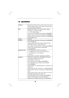
Platform CPU Chipset Memory Expansion Slot Graphics * - Micro ATX Form Factor: 9.6-in x 9.6-in, 24.4 cm x 24.4 cm - All Solid Capacitor design (100% Japan-made high-quality Conductive Polymer Capacitors) - Supports Intel® CoreTM i7 / i5 / i3 and Pentium® G6950 Processors in LGA1156 Package - ASRock H55M Pro | User Manual - Page 7
pin ATX power connector - 8 pin 12V power connector - Front panel audio connector - 3 x USB 2.0 headers (support 6 USB 2.0 ports) (see CAUTION 12) - 16Mb AMI Legal BIOS - Supports "Plug and Play" - ACPI 1.1 Compliance Wake Up Events - Supports jumperfree - SMBIOS 2.3.1 Support - CPU, CPU GFX, VCCM - ASRock H55M Pro | User Manual - Page 8
- Supports I. O. T. (Intelligent Overclocking Technology) - Supports Smart BIOS Support CD - Drivers, Utilities, AntiVirus Software (Trial Version), ASRock Software Suite (CyberLink DVD Suite and Creative Sound Blaster X-Fi MB) (OEM and Trial Version) Unique Feature - ASRock OC Tuner (see - ASRock H55M Pro | User Manual - Page 9
This motherboard supports Untied Overclocking Technology. Please read "Untied Overclocking Technology" on page 38 for details. 4. This motherboard supports Dual Channel Memory Technology. Before you implement Dual Channel Memory Technology, make sure to read the installation guide of memory modules - ASRock H55M Pro | User Manual - Page 10
MS-DOS or Windows®. With this utility, you can press key during the POST or press key to BIOS setup menu to access ASRock Instant Flash. Just launch this tool and save the new BIOS file to your USB flash drive, floppy disk or hard drive, then you can update your BIOS only in a few - ASRock H55M Pro | User Manual - Page 11
Card Support List (for Windows® XP / XP 64-bit / VistaTM / VistaTM 64-bit) Chipset Vendor ATI Model Name Chipset Name Driver ASUS-EAH4350 updates of the supported PCI Express VGA card list for CrossFireXTM Mode, please visit our website for details. ASRock website: http://www.asrock.com/support - ASRock H55M Pro | User Manual - Page 12
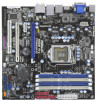
1 1 HDMI_SPDIF1 H55M Pro PCI Express 2.0 PCIE1 AUDIO CODEC Super I/O PCIE2 PCIE3 RoHS COM1 1 PCI1 LPT1 1 CMOS Battery 1394a DX10 Intel H55 FRONT_1394 USB6_7 IR1 1 1 USB10_11 1 USB8_9 CLRCMOS1 1 1 TPM1 CHA_FAN1 1 1 DDR3 2600+ SATAII_4 SATAII_2 16Mb BIOS SPEAKER1 1 CI1 - ASRock H55M Pro | User Manual - Page 13
Speaker (Lime) 10 Microphone (Pink) 11 USB 2.0 Ports (USB01) 12 USB 2.0 Port (USB2) 13 Powered eSATAII/USB Connectors 14 HDMI Port 15 VGA/ in accordance with the type of speaker you use. TABLE for Audio Output Connection Audio Output Channels Front Speaker Rear Speaker Central / Bass Line In ( - ASRock H55M Pro | User Manual - Page 14
-Streaming function, you need to connect a front panel audio cable to the front panel audio header. After restarting your computer, you will find "VIA HD Audio Deck" tool on your system. Please follow below instructions according to the OS you install. For Windows® XP / XP 64-bit OS: Please click - ASRock H55M Pro | User Manual - Page 15
This is a Micro ATX form factor (9.6" x 9.6", 24.4 x 24.4 cm) motherboard. Before you install the motherboard, study the configuration of your chassis to ensure that the motherboard fits into it. Make sure to unplug the power cord before installing or removing the motherboard. Failure to do - ASRock H55M Pro | User Manual - Page 16
Socket Body 1156-Pin Socket Overview Before you insert the 1156-Pin CPU into the socket, please check if the CPU surface is unclean or if there is any bent pin on the socket. Do not force to insert the CPU into the socket 2. This cap must be placed if returning the motherboard for after service. 16 - ASRock H55M Pro | User Manual - Page 17
key Pin1 Pin1 orientation key notch 1156-Pin CPU alignment key 1156-Pin Socket For proper inserting, please ensure to match the two orientation key notches of the CPU with the two alignment keys of the socket. Step 3-3. Carefully place the CPU into the socket by using a purely vertical motion - ASRock H55M Pro | User Manual - Page 18
with fan operation or contact other components. Please be noticed that this motherboard supports Combo Cooler Option (C.C.O.), which provides the flexible option to adopt two different CPU cooler types, Socket LGA 775 and LGA 1156. The white throughholes are for Socket LGA 1156 CPU fan. 18 - ASRock H55M Pro | User Manual - Page 19
2.5 Installation of Memory Modules (DIMM) This motherboard provides four 240-pin DDR3 (Double Data Rate 3) DIMM slots, and supports Dual Channel Memory Technology. For dual channel configuration, you always need to install identical (the same brand, speed, size and chiptype) DDR3 DIMM pair in the - ASRock H55M Pro | User Manual - Page 20
matches the break on the slot. notch break notch break The DIMM only fits in one correct orientation. It will cause permanent damage to the motherboard and the DIMM if you force the DIMM into the slot at incorrect orientation. Step 3. Firmly insert the DIMM into the slot until the retaining - ASRock H55M Pro | User Manual - Page 21
1 PCI slot and 3 PCI Express slots on this motherboard. PCI slot: PCI slot is used to install expansion cards that have the 32-bit PCI interface. PCIE slots: PCIE1 (PCIE x16 slot; Blue) is used for PCI Express x16 lane width graphics cards, or used to install PCI Express graphics cards to support - ASRock H55M Pro | User Manual - Page 22
Guide This motherboard supports supported with Windows® XP with Service Pack 2 / VistaTM / 7 OS. Quad CrossFireXTM feature are supported with Windows® VistaTM / 7 OS only. Please check AMD website for ATITM CrossFireXTM driver updates graphics card manuals for detailed installation guide. Step 1. - ASRock H55M Pro | User Manual - Page 23
Bridge Interconnects on the top of Radeon graphics cards. (CrossFire Bridge is provided with the graphics card you purchase, not bundled with this motherboard. Please refer to your graphics card vendor for details.) CrossFire Bridge or Step 2. Connect the DVI monitor cable to the DVI connector - ASRock H55M Pro | User Manual - Page 24
to installation. Please check AMD website for ATITM driver updates. Step 3. Step 4. Step 5. Install the required drivers to your system. For Windows® XP OS: A. ATITM recommends Windows® XP Service Pack 2 or higher to be installed (If you have Windows® XP Service Pack 2 or higher installed in your - ASRock H55M Pro | User Manual - Page 25
for identification or explanation and to the owners' benefit, without intent to infringe. * For further information of ATITM CrossFireXTM technology, please check AMD website for updates and details. 25 - ASRock H55M Pro | User Manual - Page 26
Display Feature This motherboard supports Surround Display upgrade. With the external add-on PCI Express VGA cards, you can easily enjoy the benefits of Surround Display feature. For the detailed instruction, please refer to the document at the following path in the Support CD: ..\ Surround Display - ASRock H55M Pro | User Manual - Page 27
P-6 USB_PWR Either end of the SATA data cable can be connected to the SATA / SATAII hard disk or the SATAII connector on this motherboard. Besides five default USB 2.0 ports on the I/O panel, there are three USB 2.0 headers on this motherboard. Each USB 2.0 header can support two USB 2.0 ports. 27 - ASRock H55M Pro | User Manual - Page 28
supports an optional wireless transmitting and receiving infrared module. This motherboard supports audio devices. 1. High Definition Audio supports Jack Sensing, but the panel wire on the chassis must support HDA to function correctly. Please follow the instruction in our manual and chassis manual - ASRock H55M Pro | User Manual - Page 29
fan (Quiet Fan) support, the 3-Pin CPU fan still can work successfully even without the fan speed control function. If you plan to connect the 3-Pin CPU fan to the CPU fan connector on this motherboard, please connect it to Pin 1-3. Pin 1-3 Connected 3-Pin Fan Installation ATX Power Connector (24 - ASRock H55M Pro | User Manual - Page 30
on the I/O panel, there is one IEEE 1394 header (FRONT_1394) on this motherboard. This IEEE 1394 header can support one IEEE 1394 port. This COM1 header supports a serial port module. 1 GND SPDIFOUT +5V HDMI_SPDIF header, providing SPDIF audio output to HDMI VGA card, allows the system to connect - ASRock H55M Pro | User Manual - Page 31
(Optional) C B A Please connect the black end (A) of HDMI_SPDIF cable to the HDMI_SPDIF header on the motherboard. Then connect the white end (B or C) of HDMI_SPDIF cable to the HDMI_SPDIF connector of HDMI VGA card. A. black end B. white end (2-pin) C. white end (3-pin) +5V SPDIFOUT GND blue - ASRock H55M Pro | User Manual - Page 32
, please carefully follow the below steps. Step 1. Install the HDMI VGA card to the• PCI Express Graphics slot on this motherboard. For the proper installation of HDMI VGA card, please refer to the installation guide on page 21. Step 2. Connect the black end (A) of HDMI_SPDIF cable to the HDMI_SPDIF - ASRock H55M Pro | User Manual - Page 33
guide. Some default setting of SATAII hard disks may not be at SATAII mode, which operate with the best performance. In order to enable SATAII function, please follow the below instruction If pin 3 and pin 4 are shorted, SATA 1.5Gb/s will be enabled. On the other .com/hdd/support/download.htm The - ASRock H55M Pro | User Manual - Page 34
Hard Disks Installation This motherboard adopts Intel® H55 bridge chipset that supports Serial ATA (SATA) / Serial ATAII (SATAII) hard disks. You may install SATA / SATAII hard disks on this motherboard for internal storage devices. This section will guide you to install the SATA / SATAII hard disks - ASRock H55M Pro | User Manual - Page 35
make sure the SATA / SATAII driver is installed into system properly. The latest SATA / SATAII driver is available on our support website: www.asrock.com 4. Make sure to use the SATA power cable & data cable, which are from our motherboard package. 5. Please follow below instructions step by step - ASRock H55M Pro | User Manual - Page 36
follow below instruction sequence to process the Hot Plug, improper procedure will cause the SATA / SATAII HDD damage and data loss. Step 1 Please connect SATA power cable 1x4-pin end Step 2 Connect SATA data cable to (White) to the power supply 1x4-pin cable. the motherboard's SATAII connector - ASRock H55M Pro | User Manual - Page 37
® XP / XP 64-bit OS on your SATA / SATAII HDDs without RAID functions, please follow below steps. AHCI mode is not supported under Windows® XP / XP 64-bit OS. Using SATA / SATAII HDDs without NCQ function STEP 1: Set up BIOS. A. Enter BIOS SETUP UTILITY Advanced screen Storage Configuration. B. Set - ASRock H55M Pro | User Manual - Page 38
Technology This motherboard supports Untied Overclocking Technology, which means during overclocking, FSB enjoys better margin due to fixed PCI / PCIE buses. Before you enable Untied Overclocking function, please enter "Overclock Mode" option of BIOS setup to set the selection from [Auto] to [Manual - ASRock H55M Pro | User Manual - Page 39
BIOS SETUP UTILITY to configure your system. The BIOS FWH chip on the motherboard stores the BIOS SETUP UTILITY. You may run the BIOS Because the BIOS software is constantly being updated, the following BIOS setup screens set up overclocking features Advanced To set up the advanced BIOS features H/W - ASRock H55M Pro | User Manual - Page 40
Time System Date [14:00:09] [Mon 11/23/2009] BIOS Version : H55M Pro P1.00 Processor Type : Intel (R) Core (TM) i3 CPU 540 @ 3.07GHz (64bit) Processor Speed : 3066MHz Microcode Update : 20652/9 Cache Size : 4096KB Total Memory DDR3_A2 DDR3_A1 DDR3_B2 DDR3_B1 : 2048MB with 256MB shared - ASRock H55M Pro | User Manual - Page 41
CPU and motherboard. It should be done at your own risk and expense. Load Memory EZ OC Setting You can use this option to load memory EZ overclocking setting. Please note that overclocing may cause damage to your memory and motherboard item to [Enabled]. Besides the BIOS option, you can also choose - ASRock H55M Pro | User Manual - Page 42
CPU Ratio Setting If the ratio status is unlocked, you will find this item appear to allow you changing the ratio value of this motherboard. DRAM Frequency If [Auto] is selected, the motherboard will detect the memory Rate BIOS SETUP UTILITY 9 [Auto] 9 [Auto] 9 [Auto] 24 [Auto] 74 [Auto] 10 [Auto - ASRock H55M Pro | User Manual - Page 43
. Configuration options: [Auto], [3] to [15]. DRAM tWTR This controls the number of DRAM clocks for TWTR. Configuration options: [Auto], [2] to [10]. DRAM tRRD This controls the number of DRAM clocks for TRRD. Configuration options: Configuration options: [Auto], [4] to [7]. DRAM tRTP This controls - ASRock H55M Pro | User Manual - Page 44
VDrop Control Use this to enable or disable ASRock VDrop control. Configuration options: [With VDrop] and [Without VDrop]. The default value is [With VDrop]. CPU Voltage Use this to select CPU Voltage. Configuration options: [Auto], [Manual] and [Overdrive Offset]. The default value is [Auto]. DRAM - ASRock H55M Pro | User Manual - Page 45
. ASRock Instant Flash ASRock Instant Flash is a BIOS flash utility embedded in Flash ROM. This convenient BIOS update tool allows you to update system BIOS without entering operating systems first like MS-DOS or Windows®. Just launch this tool and save the new BIOS file to your USB flash - ASRock H55M Pro | User Manual - Page 46
Megatrends, Inc. CPU Ratio Setting If the ratio status is unlocked, you will find this item appear to allow you changing the ratio value of this motherboard. Enhance Halt State All processors support the Halt State (C1). The C1 state is supported through the native processor instructions HLT and - ASRock H55M Pro | User Manual - Page 47
VistaTM / 7, or Linux kernel version 2.4.18 or higher. This option will be hidden if the installed CPU does not support Hyper-Threading technology. Windows® VistaTM and want to enable this function, please set this item to [Enabled]. This item will be hidden if the current CPU does not support - ASRock H55M Pro | User Manual - Page 48
3.4.2Chipset Configuration BIOS SETUP UTILITY Advanced Chipset Settings Primary Graphics Adapter Share Memory DVMT Mode Select DVMT/FIXED Memory Onboard HD Audio Front Panel Onboard HDMI HD Audio OnBoard Lan Onboard 1394 [PCI] [Auto] [DVMT Mode] [Maximum DVMT] [Auto] [Enabled] [Enabled] [Enabled - ASRock H55M Pro | User Manual - Page 49
OnBoard Lan This allows you to enable or disable the "OnBoard Lan" feature. Onboard 1394 This allows you to enable or disable the "Onboard 1394" feature. Intel VT-d Configuration Use this to enable or disable Intel® VT-d technology (Intel® Virtualization Technology for Directed I/O). The default - ASRock H55M Pro | User Manual - Page 50
ACPI Configuration BIOS SETUP UTILITY Advanced ACPI Configuration Suspend To RAM Restore on AC/Power Loss Ring-In Power On PCI Devices . Select [Auto] will enable this feature if the OS supports it. If you set this item to [Disabled], the motherboard to submit Windows® VistaTM certification. 50 - ASRock H55M Pro | User Manual - Page 51
3.4.4 Storage Configuration BIOS SETUP UTILITY Advanced Storage Configuration SATA Operation Mode [IDE] SATAII 1,2,3,4 will appear. AHCI (Advanced Host Controller Interface) supports NCQ and other new features that will improve SATA disk performance but IDE mode does not have these - ASRock H55M Pro | User Manual - Page 52
" as the example in the following instruction. BIOS SETUP UTILITY Advanced Primary IDE Master Device :ST340014A :40.0 GB :Supported :16Sectors :4 :MultiWord DMA-2 :Ultra DMA-5 :Supported [Auto] [Auto] [ for a hard disk > 512 MB under DOS and Windows; for Netware and UNIX user, select [Disabled] to - ASRock H55M Pro | User Manual - Page 53
access to maximize the IDE hard disk data transfer rate. 3.4.5PCIPnP Configuration BIOS SETUP UTILITY Advanced Advanced PCI / PnP Settings PCI Latency Timer PCI IDE BusMaster [64] [Enabled] Value in units of PCI clocks for PCI device latency timer register. +F1 F9 F10 ESC Select Screen Select - ASRock H55M Pro | User Manual - Page 54
3.4.6 Super IO Configuration BIOS SETUP UTILITY Advanced Configure Super IO Chipset Serial Port Address Infrared Port Address Parallel Port Address Parallel Port Mode EPP Version ECP Mode DMA Channel - ASRock H55M Pro | User Manual - Page 55
allowed to use under legacy OS and BIOS setup when [Disabled] is selected. If you have USB compatibility issue, it is recommended to select [Disabled] to enter OS. [BIOS Setup Only] - USB devices are allowed to use only under BIOS setup and Windows / Linux OS. USB 2.0 Rate Matching hub Use this item - ASRock H55M Pro | User Manual - Page 56
to monitor the status of the hardware on your system, including the parameters of the CPU temperature, motherboard temperature, CPU fan speed, chassis fan speed, and the critical voltage. BIOS SETUP UTILITY Main OC Tweaker Advanced H/W Monitor Boot Security Exit Hardware Health Event Monitoring - ASRock H55M Pro | User Manual - Page 57
F1 General Help F9 Load Defaults F10 Save and Exit ESC Exit v02.54 (C) Copyright 1985-2005, American Megatrends, Inc. 3.6.1 Boot Settings Configuration BIOS SETUP UTILITY Boot Boot Settings Configuration Full Screen Logo AddOn ROM Display Boot Logo Boot From Onboard LAN Bootup Num-Lock [Enabled - ASRock H55M Pro | User Manual - Page 58
option "Full Screen Logo". Configuration options: [Auto], [EuP], [Scenery] and [ASRock]. The default value is [Auto]. Boot From Onboard LAN Use this item to enable system. For the user password, you may also clear it. BIOS SETUP UTILITY Main OC Tweaker Advanced H/W Monitor Boot Security Exit - ASRock H55M Pro | User Manual - Page 59
Tweaker Advanced H/W Monitor Boot Security Exit Exit Options Save Changes and Exit Discard Changes and Exit Discard Changes Load BIOS Defaults Load Performance Setup Default (IDE/SATA) Load Performance Setup AHCI Mode Load Power Saving Setup Default Exit system setup after saving the changes. F10 - ASRock H55M Pro | User Manual - Page 60
install the necessary drivers to activate the devices. 4.2.3 Utilities Menu The Utilities Menu shows the applications software that the motherboard supports. Click on a specific item then follow the installation wizard to install it. 4.2.4 Contact Information If you need to contact ASRock or want to
-
 1
1 -
 2
2 -
 3
3 -
 4
4 -
 5
5 -
 6
6 -
 7
7 -
8
-
9
-
10
-
11
-
12
-
13
-
14
-
15
-
16
-
17
-
18
-
19
-
20
-
21
-
22
-
23
-
24
-
25
-
26
-
27
-
28
-
29
-
30
-
31
-
32
-
33
-
34
-
35
-
36
-
37
-
38
-
39
-
40
-
41
-
42
-
43
-
44
-
45
-
46
-
47
-
48
-
49
-
50
-
51
-
52
-
53
-
54
-
55
-
56
-
57
-
58
-
59
-
60
 |
 |

1
H55M Pro
User Manual
Version 1.
1
Published
March
20
10
Copyright©20
10
ASRock INC. All rights reserved.