ASRock H55M Quick Installation Guide
ASRock H55M Manual
 |
View all ASRock H55M manuals
Add to My Manuals
Save this manual to your list of manuals |
ASRock H55M manual content summary:
- ASRock H55M | Quick Installation Guide - Page 1
for backup purpose, without written consent of ASRock Inc. Products and corporate names appearing in this guide may or may not be registered trademarks or ASRock Website: http://www.asrock.com Published March 2010 Copyright©2010 ASRock INC. All rights reserved. 1 ASRock H55M Motherboard English - ASRock H55M | Quick Installation Guide - Page 2
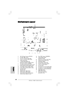
Fan Connector (PWR_FAN1) 20 Chassis Fan Connector (CHA_FAN1) 5 1156-Pin CPU Socket 21 Chassis Intrusion Header (CI1) 6 2 x 240-pin DDR3 DIMM Slots 22 TPM Header (TPM1) (Dual Channel: Header (PANEL1, Orange) (HD_AUDIO1, Lime) 17 USB 2.0 Header (USB10_11, Blue) 2 ASRock H55M Motherboard - ASRock H55M | Quick Installation Guide - Page 3
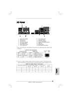
type of speaker you use. TABLE for Audio Output Connection Audio Output Channels Front Speaker Rear Speaker Central / Bass Line In (No. 8) (No. 5) (No. 4) (No. 7) 2 V -- -- -- 4 V V -- -- 6 V V V -- 8 V V V V 3 ASRock H55M Motherboard English - ASRock H55M | Quick Installation Guide - Page 4
your computer, you will find "VIA HD Audio Deck" tool on your system. Please follow below instructions according to the OS you install. For Windows® XP / XP 64-bit OS: Please click "VIA Advanced Options" screen, please check the item "Independent Headphone". 4 ASRock H55M Motherboard English - ASRock H55M | Quick Installation Guide - Page 5
introduction of the motherboard and step-by-step installation guide. More detailed information of the motherboard can be found in the user manual presented in the Support CD. Because the motherboard specifications and the BIOS software might be updated, the content of this manual will be subject - ASRock H55M | Quick Installation Guide - Page 6
@ 75Hz - Supports Auto Lip Sync, Deep Color (12bpc), xvYCC and HBR (High Bit Rate Audio) with HDMI 1.3a (Compliant HDMI monitor is required) (see CAUTION 9) - Supports HDCP function with DVI and HDMI ports - Supports Full HD 1080p Blu-ray (BD) / HD-DVD playback English 6 ASRock H55M Motherboard - ASRock H55M | Quick Installation Guide - Page 7
Legal BIOS - Supports "Plug and Play" - ACPI 1.1 Compliance Wake Up Events - Supports jumperfree - SMBIOS 2.3.1 Support - CPU, CPU GFX, VCCM, SB, VTT, PCH PLL Voltage Multi-adjustment - Supports I. O. T. (Intelligent Overclocking Technology) - Supports Smart BIOS English 7 ASRock H55M Motherboard - ASRock H55M | Quick Installation Guide - Page 8
Support CD - Drivers, Utilities, AntiVirus Software (Trial Version), ASRock Software Suite (CyberLink DVD Suite and Creative Sound Blaster X-Fi MB) (OEM and Trial Version) Unique Feature - ASRock OC Tuner (see CAUTION 13) - Intelligent Energy Saver (see CAUTION 14) - Instant Boot - ASRock - ASRock H55M | Quick Installation Guide - Page 9
output, this motherboard supports 2-channel, 4-channel, 6-channel, and 8-channel modes. Please check the table on page 3 for proper connection. 11. Before installing SATAII hard disk to SATAII connector, please read the "SATAII Hard Disk Setup Guide" on page 31 of "User Manual" in the support CD to - ASRock H55M | Quick Installation Guide - Page 10
ASRock website: http://www.asrock.com/feature/IES/index.html 15. ASRock Instant Flash is a BIOS flash utility embedded in Flash ROM. This convenient BIOS update tool allows you to update system BIOS shutdown. Before you resume the system, please check if the CPU fan on the motherboard LGA 1156. Please - ASRock H55M | Quick Installation Guide - Page 11
Catalyst 9.7 Powercolor HD4670/512MB-GDDR3 Radeon HD4670 Catalyst 9.7 * For the latest updates of the supported PCI Express VGA card list for CrossFireXTM Mode, please visit our website for details. ASRock website: http://www.asrock.com/support/index.htm English 11 ASRock H55M Motherboard - ASRock H55M | Quick Installation Guide - Page 12
you insert the 1156-Pin CPU into the socket, please check if the CPU surface is unclean or if there is any bent pin on the socket. Do not force to insert the CPU into the socket if above situation is found. Otherwise, the CPU will be seriously damaged. 12 ASRock H55M Motherboard English - ASRock H55M | Quick Installation Guide - Page 13
must be placed if returning the motherboard for after service. Step 3. Insert the 1156-Pin CPU: Step 3-1. Hold 1156-Pin Socket 1156-Pin CPU For proper inserting, please ensure to match the two orientation key notches of the CPU with the two alignment keys of the socket. 13 ASRock H55M Motherboard - ASRock H55M | Quick Installation Guide - Page 14
other components. Please be noticed that this motherboard supports Combo Cooler Option (C.C.O.), which provides the flexible option to adopt two different CPU cooler types, Socket LGA 775 and LGA 1156. The white throughholes are for Socket LGA 1156 CPU fan. 14 ASRock H55M Motherboard English - ASRock H55M | Quick Installation Guide - Page 15
H55M motherboard provides two 240-pin DDR3 (Double Data Rate 3) DIMM slots, and supports Dual Channel Memory Technology. For dual channel configuration, you always need to install two identical (the same brand, speed, size and chip-type) memory modules in the DDR3 to the motherboard and the DIMM - ASRock H55M | Quick Installation Guide - Page 16
used for PCI Express x16 lane width graphics cards, or used to install PCI Express graphics cards to support CrossFireXTM function. PCIE2 (PCIE x1 slot; White) is used for PCI Express cards with x1 lane width chassis with screws. Step 6. Replace the system cover. 16 ASRock H55M Motherboard English - ASRock H55M | Quick Installation Guide - Page 17
release in the future, please refer to ATITM graphics card manuals for detailed installation guide. Step 1. Insert one Radeon graphics card into PCIE1 slot and the other Radeon graphics card to PCIE3 slot. Make sure that the cards are properly seated on the slots. 17 ASRock H55M Motherboard English - ASRock H55M | Quick Installation Guide - Page 18
cards. (CrossFire Bridge is provided with the graphics card you purchase, not bundled with this motherboard. Please refer to your graphics card vendor for details.) CrossFire Bridge or Step 2. Connect the the D-Sub monitor cable to the DVI to D-Sub adapter.) English 18 ASRock H55M Motherboard - ASRock H55M | Quick Installation Guide - Page 19
drivers prior to installation. Please check AMD website for ATITM driver updates. Step 3. Step 4. Step 5. Install the required drivers to your system. For Windows® XP OS: A. ATITM recommends Windows® XP Service number on the Radeon graphics cards. Click "Apply". English 19 ASRock H55M Motherboard - ASRock H55M | Quick Installation Guide - Page 20
for identification or explanation and to the owners' benefit, without intent to infringe. * For further information of ATITM CrossFireXTM technology, please check AMD website for updates and details. 20 ASRock H55M Motherboard English - ASRock H55M | Quick Installation Guide - Page 21
the BIOS, you must boot up the system first, and then shut it down before you do the clearCMOS action. If you clear the CMOS, the case open may be detected. Please adjust the BIOS option "Clear Status" to clear the record of previous chassis intrusion status. English 21 ASRock H55M Motherboard - ASRock H55M | Quick Installation Guide - Page 22
2.0 headers on this motherboard. Each USB 2.0 header can support two USB 2.0 ports. (9-pin USB6_7) (see p.2 No. 15) English Print Port Header (25-pin LPT1) (see p.2 No. 24) This is an interface for print port cable that allows convenient connection of printer devices. 22 ASRock H55M Motherboard - ASRock H55M | Quick Installation Guide - Page 23
Ground (GND). D. MIC_RET and OUT_RET are for HD audio panel only. You don't need to connect them for AC'97 audio panel. E. Enter BIOS Setup Utility. Enter Advanced Settings, and then select Chipset Configuration. Set the Front Panel Control option from [Auto] to [Enabled]. 23 ASRock H55M Motherboard - ASRock H55M | Quick Installation Guide - Page 24
cable to this connector and match the black wire to the ground pin. Though this motherboard provides 4-Pin CPU fan (Quiet Fan) support, the 3-Pin CPU fan still can work successfully even without the fan speed control 20-Pin ATX Power Supply Installation 1 13 24 ASRock H55M Motherboard English - ASRock H55M | Quick Installation Guide - Page 25
ATX 12V power supply to this connector. Though this motherboard provides 8-pin ATX 12V power connector, it can Power Supply Installation 1 6 This COM1 header supports a serial port module. HDMI_SPDIF Header (3-pin cable to the HDMI_SPDIF header on the motherboard. Then connect the white end (B or - ASRock H55M | Quick Installation Guide - Page 26
SATA / SATAII HDDs without NCQ function STEP 1: Set up BIOS. A. Enter BIOS SETUP UTILITY Advanced screen Storage Configuration. B. Set the option "SATA Operation Mode" to [IDE]. STEP 2: Install Windows® 7 / 7 64-bit / VistaTM / VistaTM 64-bit OS on your system. 26 ASRock H55M Motherboard English - ASRock H55M | Quick Installation Guide - Page 27
Technology This motherboard supports Untied Overclocking Technology, which means during overclocking, FSB enjoys better margin due to fixed PCI / PCIE buses. Before you enable Untied Overclocking function, please enter "Overclock Mode" option of BIOS setup to set the selection from [Auto] to [Manual - ASRock H55M | Quick Installation Guide - Page 28
detailed information about BIOS Setup, please refer to the User Manual (PDF file) contained in the Support CD. 4. Software Support CD information This motherboard supports various Microsoft® Windows .EXE" from the BIN folder in the Support CD to display the menus. 28 ASRock H55M Motherboard English - ASRock H55M | Quick Installation Guide - Page 29
Bedienungsanleitung auf der Support-CD. Da sich Motherboard-Spezifikationen und BIOS-Software verändern können, kann der Inhalt dieses Handbuches ebenfalls jederzeit geändert werden. Für den Fall, dass sich Änderungen an diesem Handbuch ergeben, wird eine neue Version auf der ASRock-Website, ohne - ASRock H55M | Quick Installation Guide - Page 30
CoreTM i7 / i5 / i3 und Pentium® G6950- Prozessoren im LGA1156-Package - V4 + 1-Stromphasendesign - Unterstützt Intel® Turbo Boost -Speichertechnologie (siehe VORSICHT 4) - 2 x Steckplätze für DDR3 - Unterstützt DDR3 2600+(OC)/2133(OC)/1866(OC)/1600/ 1333/1066 non-ECC ASRock H55M Motherboard Deutsch - ASRock H55M | Quick Installation Guide - Page 31
7.1 CH HD Audio (VIA® VT1718S Audio Codec) - PCIE x1 Gigabit LAN 10/100/1000 Mb/s - Realtek RTL8111DL - Unterstützt Wake-On-LAN I/O Panel - 1 x PS/2-Tastaturanschluss - 16Mb AMI BIOS - AMI legal BIOS mit Unterstützung für "Plug and Play" - ACPI 1.1-Weckfunktionen Deutsch 31 ASRock H55M Motherboard - ASRock H55M | Quick Installation Guide - Page 32
BIOS Support-CD - Treiber, Dienstprogramme, Antivirussoftware (Probeversion), ASRock-Software-Suite (CyberLink DVD Suite und Creative Sound Blaster X-Fi MB) (OEM- und Testversion) Einzigartige - ASRock Sie bitte unsere Website: http://www.asrock.com Deutsch 32 ASRock H55M Motherboard - ASRock H55M | Quick Installation Guide - Page 33
bis DDR3 1333 unterstützen, wird der XMP DDR3 1600 mittels Motherboards unterstützt Stereo- und MonoModi. Der Audioausgang dieses Motherboards unterstützt 2-Kanal-, 4Kanal-, 6-Kanal- und 8-Kanal-Modi. Stellen Sie die richtige Verbindung anhand der Tabelle auf Seite 3 her. 33 ASRock H55M Motherboard - ASRock H55M | Quick Installation Guide - Page 34
-Festplatte" auf Seite 31 der "Bedienungsanleitung" auf der Support-CD, um Ihre SATAII-Festplatte dem SATAII-Modus anzugleichen. Taste im BIOS-Setup-Menü Zugang zu ASRock Instant Flash. Sie brauchen dieses Werkzeug einfach nur zu starten und die neue BIOS-Datei auf 34 ASRock H55M Motherboard Deutsch - ASRock H55M | Quick Installation Guide - Page 35
automatischen Shutdown durch. Bevor Sie das System neu starten, prüfen Sie bitte, ob der CPU-Lüfter am Motherboard richtig funktioniert von zwei verschiedenen CPU-Kühlertypen, Socket LGA 775 und LGA 1156. Beachten Sie bitte, dass nicht alle 775 CPU-Lüfter verwendet ASRock H55M Motherboard Deutsch - ASRock H55M | Quick Installation Guide - Page 36
(Sockel) 1156-Pin Sockel Übersicht Bevor Sie die 1156-Pin CPU in den Sockel sitzen, prüfen Sie bitte, ob die CPU-Oberfläche sauber ist und keine der Kontakte verbogen sind. Setzen Sie die CPU nicht mit Gewalt in den Sockel, dies kann die CPU schwer beschädigen. Deutsch 36 ASRock H55M Motherboard - ASRock H55M | Quick Installation Guide - Page 37
Sie den Ladehebel, bis er in geöffneter Position steht, ca. 135 Grad. Schritt 1-3. Drehen Sie die Ladeplatte, bis sie in geöffneter Position steht, ca. 100 Grad Pin1 Orientierungskerbe 1156-Pin CPU Ausrichtungsmarkierung 1156-Pin Sockel ASRock H55M Motherboard Pin1 37 Deutsch - ASRock H55M | Quick Installation Guide - Page 38
(IHS). Schritt 4-2. Drücken Sie leicht auf die Ladeplatte und schließen Sie den Ladehebel. Schritt 4-3. Sichern Sie Ladehebel und Ladeplatte mithilfe des Hebelverschlusses. 38 ASRock H55M Motherboard Deutsch - ASRock H55M | Quick Installation Guide - Page 39
bitte, dass dieses Motherboard die ComboKühleroption unterstützt, die eine flexible Möglichkeit zur Aufnahme von zwei verschiedenen CPU-Kühlertypen, Socket LGA 775 und LGA 1156, bietet. Das weiße Durchgangsloch ist für den CPULüfter im Socket LGA 1156 vorgesehen. 39 ASRock H55M Motherboard Deutsch - ASRock H55M | Quick Installation Guide - Page 40
H55M Motherboard bietet zwei 240polige DDR3 (Double Data Rate 3) DIMMSteckplätze und unterstützt Zweikanal-Speichertechnologie. Es müssen immer zwei identische Speichermodule (selbe Marke, Geschwindigkeit, Größe und ChipArt) in den DDR3 DIMM-Modul fest an Ort und Stelle sitzt. ASRock H55M Motherboard - ASRock H55M | Quick Installation Guide - Page 41
-Steckplätze) Es gibt einen 1 PCI-Steckplätze und 3 PCI Express-Steckplätze am H55M Motherboard. PCI-Slots: PCI-Slots werden zur Installation von Erweiterungskarten mit dem 32bit PCI-Interface genutzt. 4: Befestigen Sie die Karte mit der Schraube aus Schritt 2. Deutsch 41 ASRock H55M Motherboard - ASRock H55M | Quick Installation Guide - Page 42
-Funktion von den Betriebssystemen Windows® XP mit Service Pack 2 / VistaTM / 7 unterstützt Updates gibt. Beachten Sie den detailliert erklärten Installationsablauf auf Seite 17. 2.6 "Surround Display" Dieses Motherboard Support-CD: ..\ Surround Display Information 42 ASRock H55M Motherboard Deutsch - ASRock H55M | Quick Installation Guide - Page 43
das CMOS gelöscht wurde. Wenn Sie den CMOS-Inhalt gleich nach dem Aktualisieren des BIOS löschen müssen, müssen Sie zuerst das System starten und dann wieder ausschalten, bevor des vorherigen Gehäuseindringungsstatus die BIOS-Option "Status leeren" ein. Deutsch 43 ASRock H55M Motherboard - ASRock H55M | Quick Installation Guide - Page 44
sse. Wenn Sie Jumperkappen auf Header und Anschlüsse setzen, wird das Motherboard unreparierbar beschädigt! Seriell-ATAII-Anschlüsse (SATAII_1: siehe S.2 - No den I/O-Anschlüssen befinden sich drei USB 2.0Anschlussleisten am Motherboard. Pro USB 2.0Anschlussleiste werden zwei USB 2.0-Ports unterstü - ASRock H55M | Quick Installation Guide - Page 45
ützt digitale Identitäten und sorgt für Plattformintegrität. Dieser Header unterstützt ein optionales, drahtloses Sendeund Empfangs-Infrarotmodul. Dieses Motherboard unterstützt die GEHÄUSE OFFEN-Erkennungsfunktion, die feststellt, ob die Gehäuseabdeckung entfernt wurde. Für diese Funktion ist ein - ASRock H55M | Quick Installation Guide - Page 46
sse müssen nicht an die AC'97-Audioleiste angeschlossen werden. E. Rufen Sie das BIOS-Setup-Dienstprogramm auf. Wechseln Sie zu Erweiterte Einstellungen und wählen Sie Chipset-Konfiguration. üssen, wobei der schwarze Draht an den Schutzleiterstift angeschlossen wird. 46 ASRock H55M Motherboard - ASRock H55M | Quick Installation Guide - Page 47
7) 12 24 Verbinden Sie die ATXStromversorgung mit diesem Header. 1 13 Obwohl dieses Motherboard einen 24-pol. ATX-Stromanschluss 12 24 bietet, kann es auch mit einem modifizierten AnschlussHeader wird verwendet, um ein COM-Anschlussmodul zu unterstützen. 47 ASRock H55M Motherboard Deutsch - ASRock H55M | Quick Installation Guide - Page 48
Anschluss. Bitte verbinden Sie das schwarze Ende (A) des HDMI_SPDIF-Kabels mit dem HDMI_SPDIF-Anschluss am Motherboard. Schließen Sie dann das weiße Ende (B oder C) des HDMI_SPDIF-Kabels an den je nach dem zu installierenden Betriebssystem den folgenden Schritten. 48 ASRock H55M Motherboard - ASRock H55M | Quick Installation Guide - Page 49
A. Rufen Sie das BIOS SETUP UTILITY auf, wählen Sie den „Advanced"- Bildschirm (Erweitert), dann „Storage Configuration". B. Stellen Sie "SATA Operation Mode" auf [AHCI]. SCHRITT 2: Installieren Sie Windows® 7 / 7 64-Bit / VistaTM / VistaTM 64-Bit in Ihrem System. 49 ASRock H55M Motherboard Deutsch - ASRock H55M | Quick Installation Guide - Page 50
-Verzeichnis der Support-CD, um die Menüs aufzurufen. Das Setup-Programm soll es Ihnen so leicht wie möglich machen. Es ist menügesteuert, d.h. Sie können in den verschiedenen Untermenüs Ihre Auswahl treffen und die Programme werden dann automatisch installiert. 50 ASRock H55M Motherboard Deutsch - ASRock H55M | Quick Installation Guide - Page 51
informations particulières au modèle que vous utilisez. www.asrock.com/support/index.asp 1.1 Contenu du paquet Carte mère ASRock H55M (Facteur de forme Micro ATX: 9.6 pouces x 8.8 pouces, 24.4 cm x 22.4 cm) Guide d'installation rapide ASRock H55M CD de soutien ASRock H55M Deux câbles de données - ASRock H55M | Quick Installation Guide - Page 52
ée max 1759MB (voir ATTENTION 7) - Trois options de sortie VGA: D-Sub, DVI-D et HDMI (voir ATTENTION 8) - Prend en charge le HDMI 1.3a avec une résolution maximale jusqu'à 1920x1200 - Prend en charge le DVI avec une résolution maximale jusqu'à 1920x1200 @ 60Hz 52 ASRock H55M Motherboard Français - ASRock H55M | Quick Installation Guide - Page 53
arrière Connecteurs - Prend en charge le D-Sub avec une résolution maximale haute définition de CH (codec audio VIA® VT1718S) - PCIE x1 Gigabit LAN 10/100/1000 Mb/s - Realtek RTL8111DL - Support du Wake-On-LAN I/O Panel - 1 x port clavier PS/2 - 1 x port VGA/D- Français 53 ASRock H55M Motherboard - ASRock H55M | Quick Installation Guide - Page 54
) BIOS - 16Mb BIOS AMI - BIOS AMI - Support du "Plug and Play" - Compatible pour événements de réveil ACPI 1.1 - Gestion jumperless - Support SMBIOS plus amples informations sur les produits, s'il vous plaît visitez notre site web: http://www.asrock.com Français 54 ASRock H55M Motherboard - ASRock H55M | Quick Installation Guide - Page 55
le Guide « Installation du disque dur SATAII » à la page 31 du « Manuel de l'utilisateur » qui se trouve sur le CD de support pour régler votre lecteur de disque dur SATAII au mode SATAII. Vous pouvez aussi directement connecter le disque dur SATA au connecteur SATAII. 55 ASRock H55M Motherboard - ASRock H55M | Quick Installation Guide - Page 56
carte mère. 17. Même si cette carte mère offre un contrôle sans souci, il n'est pas recommandé d'y appliquer un over clocking. Des fréquences de bus CPU autres que celles recommandées risquent de rendre le système instable ou d'endommager le CPU et la carte mère. 56 ASRock H55M Motherboard Français - ASRock H55M | Quick Installation Guide - Page 57
flexible pour adopter deux types différents de refroidisseur sde CPU, les sockets LGA 775 et LGA 1156. Veuillez noter que tous les ventilateurs de CPU 775 ne peuvent pas être utilisés. 20. EuP de consulter votre fournisseur de courant pour plus de détails. 57 ASRock H55M Motherboard Français - ASRock H55M | Quick Installation Guide - Page 58
broches dans le socket, veuillez vérifier que la surface du processeur est bien propre, et qu'il n'y a aucune broche tordue sur le socket. Si c'est le cas, ne forcez pas pour insérer le processeur dans le socket. Sinon, le processeur sera gravement endommagé. Français 58 ASRock H55M Motherboard - ASRock H55M | Quick Installation Guide - Page 59
3-2. Orientez le paquet avec le dissipateur thermique intégré (IHS) vers le haut. Repérez la broche 1 et les deux encoches d'orientation. Encoche d'orientation broche 1 Détrompeur Encoche d'orientation Processeur 1156 broches Détrompeur Socket 1156 broches ASRock H55M Motherboard broche 1 59 - ASRock H55M | Quick Installation Guide - Page 60
thermique. L'exemple ci-dessous illustre l'installation du dissipateur thermique pour un processeur 1366 broches. (Appliquez le matériau d'interface thermique) Etape 1. Appliquez le matériau d'interface thermique au centre de IHS sur la surface du socket. Français 60 ASRock H55M Motherboard - ASRock H55M | Quick Installation Guide - Page 61
mère prend en charge l'option Combo Cooler Option (C.C.O.), qui offre un choix flexible pour adopter deux types différents de refroidisseurs de CPU, les sockets LGA 775 et LGA 1156. Les trous traversant blancs sont pour le ventilateur de CPU au socket LGA 1156. Français 61 ASRock H55M Motherboard - ASRock H55M | Quick Installation Guide - Page 62
chip) dans les emplacements DDR3 DIMM pour activer la technologie Dual Channel Memory. Sinon, le système le module DIMM dans son emplacement jusqu'à ce que les clips de maintien situés aux deux extrémités se ferment complètement et que le module DIMM soit inséré correctement. ASRock H55M Motherboard - ASRock H55M | Quick Installation Guide - Page 63
connecteur que vous voulez utiliser. Gardez la vis pour un usage ultérieur. Etape 3. Alignez la carte sur le connecteur et appuyez fermement jusqu'à l'insertion complète de la carte dans son emplacement. Etape 4. Fixez la carte sur le châssis à l'aide d'une vis. Français 63 ASRock H55M Motherboard - ASRock H55M | Quick Installation Guide - Page 64
Express, vous pouvez facilement jouir des avantages de la caractéristique de l'affichage Surround. Pour les instructions détaillées, veuillez vous reporter au document qui se trouve sur le chemin suivant dans le CD d'assistance : ..\ Surround Display Information 64 ASRock H55M Motherboard Français - ASRock H55M | Quick Installation Guide - Page 65
ération d'effacement de la CMOS. Si vous effacez la CMOS, il se peut qu'une ouverture du boîtier soit détectée. Veuillez ajuster l'option du BIOS "Clear Status" (Effacer l'état) pour effacer la mention d'état d'intrusion dans le châssis. Français 65 ASRock H55M Motherboard - ASRock H55M | Quick Installation Guide - Page 66
/ SATAII ou au connecteur SATAII sur la carte mere. A côté des quatre ports USB 2.0 par défaut sur le panneau E/S, il y a trois embases USB 2.0 sur cette carte mère. Chaque embase USB 2.0 peut prendre en charge 2 ports USB 2.0. (USB6_7 br.9) (voir p.2 No. 15) Français 66 ASRock H55M Motherboard - ASRock H55M | Quick Installation Guide - Page 67
des réseaux, protège les identités numériques, et assure l'intégrité de la plate-forme. Cet en-tête supporte un module infrarouge le châssis. C'est une interface pour un câble audio en façade qui permet le branchement et le contrôle commodes de périphériques audio. 67 ASRock H55M Motherboard - ASRock H55M | Quick Installation Guide - Page 68
ventilateur et faites correspondre le fil noir à la broche de terre. Connecteur du ventilateur de l'UC (CPU_FAN1 br. 4) (voir p.2 No. 3) 1 2 3 4 Veuillez connecter le câble de ventilateur d'UC sur ce connecteur et brancher le fil noir sur la broche de terre. Français 68 ASRock H55M Motherboard - ASRock H55M | Quick Installation Guide - Page 69
es correspondre che de terre. ien que cette carte mère offre un support de (Ventilateur silencieux) ventilateur de CPU à 4 broches , le ventilateur de CPU à 3 broches peut bien fonctionner même sans la fonction ée pour prendre en charge un module de port COM. Français 69 ASRock H55M Motherboard - ASRock H55M | Quick Installation Guide - Page 70
Guide d'installation des pilotes Pour installer les pilotes sur votre système, veuillez d'abord insérer le CD dans votre lecteur optique. Puis, les SATAII sans les fonctions RAID, veuillez suivre les procédures ci-dessous, en fonction de l'OS que vous installez. Français 70 ASRock H55M Motherboard - ASRock H55M | Quick Installation Guide - Page 71
le BIOS. A. Accédez à BIOS SETUP UTILITY (Utilitaire de configuration BIOS) écran Avancé Configuration Storage. B. Réglez «SATA Operation Mode « sur [AHCI]. ETAPE 2: Installer le système d'exploitation Windows® 7 / 7 64-bit / VistaTM / VistaTM 64-bit sur votre système. 71 ASRock H55M Motherboard - ASRock H55M | Quick Installation Guide - Page 72
choix prédéterminés. Pour des informations détaillées sur le BIOS, veuillez consulter le Guide de l'utilisateur (fichier PDF) dans le CD technique. 4. Informations sur le CD de support Cette carte mère supporte divers systèmes d'exploitation Microsoft® Windows®: 7 / 7 64 bits / VistaTM / VistaTM 64 - ASRock H55M | Quick Installation Guide - Page 73
.asrock.com/support/index.asp 1.1 Contenuto della confezione Scheda madre ASRock H55M (Micro ATX Form Factor: 9.6-in x 8.8-in, 24.4 cm x 22.4 cm) Guida di installazione rapida ASRock H55M CD di supporto ASRock H55M Due cavi dati Serial ATA (SATA) (opzionali) Un I/O Shield 73 ASRock H55M Motherboard - ASRock H55M | Quick Installation Guide - Page 74
i7 / i5 / i3 e Pentium® G6950 nel pacchetto LGA1156 - Struttura di fase con alimentazione V4 + 1 - Supporto Dual Channel Memory (vedi ATTENZIONE 4) - 2 x slot DDR3 DIMM - Supporto DDR3 2600+(OC)/2133(OC)/1866(OC)/1600/1333/ 1066 non- (vedi ATTENZIONE 9) 74 ASRock H55M Motherboard Italiano - ASRock H55M | Quick Installation Guide - Page 75
audio sul pannello frontale - 3 x Collettore USB 2.0 (supporta 6 porte USB 2.0) (vedi ATTENZIONE 12) - 16Mb AMI BIOS - Suppor AMI legal BIOS - Supporta "Plug and Play" - Compatibile con ACPI 1.1 wake up events - Supporta jumperfree - Supporta SMBIOS 2.3.1 Italiano 75 ASRock H55M Motherboard - ASRock H55M | Quick Installation Guide - Page 76
BIOS supportato CD di - Driver, utilità, software antivirus (Versione dimostrativa), Suite supporto software ASRock (Suite CyberLink DVD e Creative Sound Blaster X-Fi MB) (OEM e Versione demo) Caratteristica - Sintonizzatore ASRock dall'overclocking. Italiano 76 ASRock H55M Motherboard - ASRock H55M | Quick Installation Guide - Page 77
DDR3 1333, XMP DDR3 "Manuale le Vostre unita' hardware per ottenere la migliore prestazione in Windows®. Prego visitare il nostro sito Internet per ulteriori dettagli circa l'uso del Sintonizzatore ASRock OC. ASRock website: http://www.asrock.com/feature/OCTuner/index.htm 77 ASRock H55M Motherboard - ASRock H55M | Quick Installation Guide - Page 78
POST, oppure il tasto nel menu BIOS per accedere ad ASRock Instant Flash. Avviare questo strumento e salvare il nuovo file BIOS nell'unità Flash USB, dischetto (disco floppy LGA 775 e LGA 1156. Notare che non possono essere usate tutte le ventole CPU 775. 78 ASRock H55M Motherboard Italiano - ASRock H55M | Quick Installation Guide - Page 79
% con un consumo di corrente di 100 mA. Per la scelta di un'alimentatore predisposto EuP consigliamo di verificare ulteriori dettagli con il produttore. 79 ASRock H55M Motherboard Italiano - ASRock H55M | Quick Installation Guide - Page 80
eccessivamente le viti! 1156-Pin nel socket, verificare che la superficie della CPU sia pulita e che non ci siano pin piegati nel socket. Non forzare l'inserimento della CPU nel socket se ci sono pin piegati. In caso contrario la CPU potrebbe essere seriamente danneggiata. 80 ASRock H55M Motherboard - ASRock H55M | Quick Installation Guide - Page 81
scheda madre deve essere restituita per l'assistenza. Linea nera Fase 3. Inserire la CPU 1156-Pin: Fase 3-1. Tenere la CPU dai bordi segnati con linee nere. Fase 3-2. Pin1 Dente di orientamento CPU da 1156-Pin Tacca di allineamento Socket da 1156-Pin ASRock H55M Motherboard Pin1 81 Italiano - ASRock H55M | Quick Installation Guide - Page 82
verticale. Fase 3-4. Verificare che la CPU sia all'interno della presa e combaci in modo appropriato con le chiavi d'orientamento. Fase 4. Chiudere la presa: Fase 4-1. Ruotare la piastra di carico sull'IHS. della linguetta di ritenzione della leva di carico. Italiano 82 ASRock H55M Motherboard - ASRock H55M | Quick Installation Guide - Page 83
della ventola sono (Cavi della ventola sul lato più vicino all'header della MB) orientati sul lato più vicino al connettore della ventola della CPU presente sulla CPU, Socket LGA 775 e LGA 1156. I fori di colore bianco sono per la ventola CPU Socket LGA 1156. Italiano 83 ASRock H55M Motherboard - ASRock H55M | Quick Installation Guide - Page 84
2.3 Installazione dei moduli di memoria (DIMM) La motherboard H55M dispone di due slot DIMM DDR3 (Double Data Rate 3) a 240 pin e supporta la tecnologia Dual Channel Memory. Per attivare ritegno alle due estremità e fino ad installare correttamente la DIMM nella sua sede. 84 ASRock H55M Motherboard - ASRock H55M | Quick Installation Guide - Page 85
sullo slot che si intende utilizzare. Tenere a portata di mano le viti. Step 3. Allineare il connettore della scheda con lo slot e premere con decisione finché la scheda è completamente inserita nello slot. Step 4. Agganciare la scheda allo chassis con le viti. Italiano 85 ASRock H55M Motherboard - ASRock H55M | Quick Installation Guide - Page 86
dai sistemi operativi Windows® XP con Service Pack 2 / VistaTM / 7. La AMD per gli aggiornamenti dei driver ATITM CrossFireXTM. Attenersi alle le istruzioni dettagliate, fare riferimento al documento nel seguente percorso sul CD di supporto: ..\ Surround Display Information 86 ASRock H55M Motherboard - ASRock H55M | Quick Installation Guide - Page 87
di cancellare i dati presenti nel CMOS. I dati del CMOS comprendono le informazioni di configurazione quali la password di sistema, data, ora, e del BIOS "Clear Status" (Cancella stato) per cancellare la registrazione del precedente stato d'intrusione chassis. Italiano 87 ASRock H55M Motherboard - ASRock H55M | Quick Installation Guide - Page 88
2.0 predefinite nel pannello I/O, la scheda madre dispone di tre intestazioni USB 2.0. Ciascuna intestazione USB 2.0 supporta due porte USB 2.0. (9-pin USB6_7) (vedi p.2 Nr. 15) Italiano 88 ASRock H55M Motherboard - ASRock H55M | Quick Installation Guide - Page 89
dati. Un sistema di TPM aiuta anche a migliorare la sicurezza di rete, protegge le identità digitali e garantisce l'integrità della piattaforma. Questo collettore supporta moduli ad infrarossi . Che consente connessione facile e controllo dei dispositivi audio. Italiano 89 ASRock H55M Motherboard - ASRock H55M | Quick Installation Guide - Page 90
Collegare le casse del telaio a questo collettore. Collegare i cavi della ventola ai corrispondenti connettori facendo combaciare il cavo nero col pin di terra. Collegare il cavo della ventolina CPU a questo connettore e far combaciare il filo nero al pin terra. Italiano 90 ASRock H55M Motherboard - ASRock H55M | Quick Installation Guide - Page 91
elettrica 4-Pin ATX 12V 1 6 Collettore porta COM (9-pin COM1) (vedi p.2 Nr. 25) Questo collettore porta COM è utilizzato per supportare il modulo porta COM. Italiano 91 ASRock H55M Motherboard - ASRock H55M | Quick Installation Guide - Page 92
à ottica. Quindi, i driver compatibili con il sistema vengono rilevati automaticamente ed elencati nella pagina del driver del CD in dotazione. Per l'installazione dei driver necessari, procedere in base seguono relative al sistema operativo che si installa. Italiano 92 ASRock H55M Motherboard - ASRock H55M | Quick Installation Guide - Page 93
seguire le BIOS. A. Entrare in BIOS SETUP UTILITY (UTILITÀ DI CONFIGURAZIONE DEL BIOS) Advanced screen (Avanzate) Storage Configuration. B. Impostare "SATA Operation Mode" su [AHCI]. Passo 2: Installazione di Windows® 7 / 7 64-bit / VistaTM / VistaTM 64-bit sul sistema. 93 ASRock H55M Motherboard - ASRock H55M | Quick Installation Guide - Page 94
informazioni più dettagliate circa il Setup del BIOS, fare riferimento al Manuale dell'Utente (PDF file) contenuto nel supporto a corredo della scheda madre contiene i driver e utilità necessari a potenziare le caratteristiche della scheda. Inserire il CD di supporto ASRock H55M Motherboard Italiano - ASRock H55M | Quick Installation Guide - Page 95
.asrock.com/support/index.asp 1.1 Contenido de la caja Placa base ASRock H55M (Factor forma Micro ATX: 24,4 cm x 22,4 cm, 9,6" x 8,8") Guía de instalación rápida de ASRock H55M CD de soporte de ASRock H55M Dos cables de datos Serial ATA (SATA) (Opcional) Una protección I/O 95 ASRock H55M Motherboard - ASRock H55M | Quick Installation Guide - Page 96
Intel® CoreTM i7 / i5 / i3 y Pentium® G6950 con encapsulado LGA1156 - Diseño de fases de potencia V4 + 1 - Admite la de Memoria de Doble Canal (ver ATENCIÓN 4) - 2 x DDR3 DIMM slots - Apoya DDR3 2600+(OC)/2133(OC)/1866(OC)/1600/1333/1066 non-ECC, memoria ATENCIÓN 9) ASRock H55M Motherboard Español - ASRock H55M | Quick Installation Guide - Page 97
- Conector de audio de panel frontal - 3 x Cabezal USB 2.0 (admite 6 puertos USB 2.0 adicionales) (vea ATENCIÓN 12) - 16Mb AMI BIOS - AMI legal BIOS - Soporta "Plug and Play" - ACPI 1.1 compliance wake up events - Soporta "jumper free" - Soporta SMBIOS 2.3.1 Español 97 ASRock H55M Motherboard - ASRock H55M | Quick Installation Guide - Page 98
BIOS CD de soport - Controladores, Utilerías, Software de Anti Virus (Versión de prueba), conjunto de aplicaciones ASRock (CyberLink DVD Suite y Creative Sound Blaster X-Fi MB) sobre los productos, por favor visite nuestro sitio web: http://www.asrock.com Español 98 ASRock H55M Motherboard - ASRock H55M | Quick Installation Guide - Page 99
reloj, incluido el ajuste del BIOS, aplicando la tecnología de aumento Boost. 2. Por favor consulte página 44 del Manual del Usuario en el soporte CD sobre la aquellas CPU que sólo admitan DDR3 1333 como máximo, el uso de XMP DDR3 1600 es posible utilizando funciones ASRock H55M Motherboard Español - ASRock H55M | Quick Installation Guide - Page 100
duros SATAII" en la página 31 del "Manual de usuario" que se incluye en el CD ASRock Instant Flash es una utilidad de programación del BIOS que se encuentra almacenada en la memoria Flash ROM. Esta sencilla herramienta de actualización de BIOS le permitirá actualizar el BIOS ASRock H55M Motherboard - ASRock H55M | Quick Installation Guide - Page 101
disipador de CPU diferentes, correspondientes a los zócalos LGA 775 y LGA 1156. Recuerde que no es posible el uso de todos los ventiladores para CPU EuP, le recomendamos que consulte con el fabricante de la fuente de alimentación para obtener más detalles. 101 ASRock H55M Motherboard Español - ASRock H55M | Quick Installation Guide - Page 102
1156 agujas en el socket, compruebe que la superficie de la CPU se encuentra limpia y no hay ninguna aguja torcida en el socket. No introduzca la CPU en el socket por la fuerza si se produce la situación anterior. Si lo hace, puede producir daños graves en la CPU. 102 ASRock H55M Motherboard - ASRock H55M | Quick Installation Guide - Page 103
colocarse si la placa base vuelve tras ser reparada. Paso 3. Inserte la CPU de 1156 agujas: Paso 3-1. Sostenga la CPU por los bordes marcados con líneas negras. 1 Muesca de orientación CPU de 1156 agujas Tecla de alineación Socket de 1156 agujas ASRock H55M Motherboard aguja 1 103 Español - ASRock H55M | Quick Installation Guide - Page 104
la CPU Para una correcta instalación, consulte los manuales de instrucciones del ventilador y el disipador de 1156 agujas. Paso 1. Aplique el material termal de interfaz en el centro del IHS de la superficie del socket. (Aplique el material termal de interfaz) Español 104 ASRock H55M Motherboard - ASRock H55M | Quick Installation Guide - Page 105
ón combinada (C.C.O.), una opción flexible que puede adaptarse a dos tipos de disipador de CPU diferentes, correspondientes a los zócalos LGA 775 y LGA 1156. Los orificios perforados de color blanco están destinados al ventilador de CPU para zócalos LGA 1156. Español 105 ASRock H55M Motherboard - ASRock H55M | Quick Installation Guide - Page 106
sistema funcionará en el modo de un solo canal. 1. No se permite instalar módulos DDR o DDR2 en la ranura DDR3; si lo hace, esta placa base y los módulos DIMM pueden resultar dañados. 2. Si instala únicamente un su sitio y la DIMM se haya asentado apropiadamente. 106 ASRock H55M Motherboard Español - ASRock H55M | Quick Installation Guide - Page 107
2.4 Ranuras de Expansión (ranuras PCI y ranuras PCI Express) La placa madre H55M cuenta con 1 ranuras PCI y 3 ranuras PCI Express. Ranura PCI: Para instalar tarjetas de ranura. Empuje firmemente la tarjeta en la ranura. Paso 4. Asegure la tarjeta con tornillos. 107 ASRock H55M Motherboard Español - ASRock H55M | Quick Installation Guide - Page 108
Manual inteligente y un innovador mecanismo de interconexión, CrossFireXTM le permitirá disfrutar del nivel de rendimiento más alto , CrossFireXTM es compatible con los sistemas operativos Windows® XP con Service Pack 2 / VistaTM / 7. La función Quad CrossFireXTM es ASRock H55M Motherboard Español - ASRock H55M | Quick Installation Guide - Page 109
necesita borrar la CMOS cuando acabe de finalizar la actualización de la BIOS, debe arrancar primero el sistema y, a continuación, apagarlo antes de BIOS "Clear Status" (Borrar estado) para borrar el registro del estado de intrusión anterior del chasis. Español 109 ASRock H55M Motherboard - ASRock H55M | Quick Installation Guide - Page 110
de conexiones USB 2.0 en esta placa base. Cada una de estas bases de conexiones admite dos puertos USB 2.0. (9-pin USB6_7) (vea p.2, N. 15) Español 110 ASRock H55M Motherboard - ASRock H55M | Quick Installation Guide - Page 111
(9-pin HD_AUDIO1) (vea p.2, N. 31) Este es una interface para cable de audio de panel frontal que permite conexión y control conveniente de apparatos de Audio. 111 ASRock H55M Motherboard Español - ASRock H55M | Quick Installation Guide - Page 112
operar correctamente. Por favor, siga las instrucciones en nuestro manual y en el manual de chasis para instalar su sistema. 2. Si utiliza el AC'97. E. Entre en la Utilidad de configuración del BIOS Entre en Configuración avanzada y, a continuación, seleccione Configuración del ASRock H55M Motherboard - ASRock H55M | Quick Installation Guide - Page 113
p.2, N. 25) Instalación de Fuente de Energía de 4-Pin ATX 12V 1 6 Este cabezal del puerto COM se utiliza para admitir un módulo de puerto COM. 113 ASRock H55M Motherboard Español - ASRock H55M | Quick Installation Guide - Page 114
discos duros SATA / SATAII sin funciones RAID, siga los procedimientos que se indican a continuación en función del sistema operativo que tenga instalado. Español 114 ASRock H55M Motherboard - ASRock H55M | Quick Installation Guide - Page 115
/ SATAII con funciones NCQ PASO 1: Configuración de la BIOS. A. Entre en BIOS SETUP UTILITY Òpantalla Avanzada Storage Configuración. B. Configure la "SATA Operation Mode" a [AHCI]. PASO 2: Instale Windows® 7 / 7 64 bits / VistaTM / VistaTM 64 bits en su sistema. 115 ASRock H55M Motherboard Español - ASRock H55M | Quick Installation Guide - Page 116
Para información detallada sobre como configurar la BIOS, por favor refiérase al Manual del Usuario (archivo PDF) contenido en el CD. 4.Información de Software Support CD Esta placa-base soporta diversos tipos el archivo "ASSETUP.EXE" para iniciar la instalación. 116 ASRock H55M Motherboard Español - ASRock H55M | Quick Installation Guide - Page 117
138 ASRock H55M Motherboard - ASRock H55M | Quick Installation Guide - Page 118
® ® ® ® ® ® ® ® 139 ASRock H55M Motherboard - ASRock H55M | Quick Installation Guide - Page 119
140 ASRock H55M Motherboard - ASRock H55M | Quick Installation Guide - Page 120
® ® " ® ® " ASRock H55M Motherboard 141 - ASRock H55M | Quick Installation Guide - Page 121
® ® ® ® ® " " " " ® ® 142 ASRock H55M Motherboard - ASRock H55M | Quick Installation Guide - Page 122
143 ASRock H55M Motherboard - ASRock H55M | Quick Installation Guide - Page 123
144 ASRock H55M Motherboard - ASRock H55M | Quick Installation Guide - Page 124
Pin1 Pin1 145 ASRock H55M Motherboard - ASRock H55M | Quick Installation Guide - Page 125
146 ASRock H55M Motherboard - ASRock H55M | Quick Installation Guide - Page 126
147 ASRock H55M Motherboard - ASRock H55M | Quick Installation Guide - Page 127
148 ASRock H55M Motherboard - ASRock H55M | Quick Installation Guide - Page 128
® ® 149 ASRock H55M Motherboard - ASRock H55M | Quick Installation Guide - Page 129
"" "" "" "" " " 150 ASRock H55M Motherboard - ASRock H55M | Quick Installation Guide - Page 130
SATAII_3 SATAII_1 SATAII_2 SATAII_4 151 ASRock H55M Motherboard - ASRock H55M | Quick Installation Guide - Page 131
152 ASRock H55M Motherboard - ASRock H55M | Quick Installation Guide - Page 132
1 2 3 4 12 24 1 13 ASRock H55M Motherboard 153 - ASRock H55M | Quick Installation Guide - Page 133
4 8 1 6 12 24 1 13 4 8 1 6 154 ASRock H55M Motherboard - ASRock H55M | Quick Installation Guide - Page 134
12 24 1 13 4 8 1 6 C B A ® ® ® ® ® 155 ASRock H55M Motherboard - ASRock H55M | Quick Installation Guide - Page 135
® ® ® ® ® 156 ASRock H55M Motherboard - ASRock H55M | Quick Installation Guide - Page 136
" " \\ " " 157 ASRock H55M Motherboard - ASRock H55M | Quick Installation Guide - Page 137
158 ASRock H55M Motherboard - ASRock H55M | Quick Installation Guide - Page 138
® ® ® ® ® ® ® 159 ASRock H55M Motherboard - ASRock H55M | Quick Installation Guide - Page 139
® 160 ASRock H55M Motherboard - ASRock H55M | Quick Installation Guide - Page 140
® ® ® 161 ASRock H55M Motherboard - ASRock H55M | Quick Installation Guide - Page 141
® ® " ® " ® ® ® ® ® 162 TM TM ® ® ® ASRock H55M Motherboard - ASRock H55M | Quick Installation Guide - Page 142
® - 163 ASRock H55M Motherboard - ASRock H55M | Quick Installation Guide - Page 143
164 ASRock H55M Motherboard - ASRock H55M | Quick Installation Guide - Page 144
165 ASRock H55M Motherboard - ASRock H55M | Quick Installation Guide - Page 145
166 ASRock H55M Motherboard - ASRock H55M | Quick Installation Guide - Page 146
167 ASRock H55M Motherboard - ASRock H55M | Quick Installation Guide - Page 147
168 ASRock H55M Motherboard - ASRock H55M | Quick Installation Guide - Page 148
169 ASRock H55M Motherboard - ASRock H55M | Quick Installation Guide - Page 149
® ® \ 170 ASRock H55M Motherboard - ASRock H55M | Quick Installation Guide - Page 150
171 ASRock H55M Motherboard - ASRock H55M | Quick Installation Guide - Page 151
SATAII_4 SATAII_2 SATAII_3 SATAII_1 172 ASRock H55M Motherboard - ASRock H55M | Quick Installation Guide - Page 152
173 ASRock H55M Motherboard - ASRock H55M | Quick Installation Guide - Page 153
1 2 3 4 174 ASRock H55M Motherboard - ASRock H55M | Quick Installation Guide - Page 154
12 24 1 13 4 8 1 6 12 24 1 13 4 8 1 6 175 ASRock H55M Motherboard - ASRock H55M | Quick Installation Guide - Page 155
C B A ® ® ® ® ® ® 176 ASRock H55M Motherboard - ASRock H55M | Quick Installation Guide - Page 156
® ® ® ® 177 ASRock H55M Motherboard - ASRock H55M | Quick Installation Guide - Page 157
® ® TM TM 178 ASRock H55M Motherboard - ASRock H55M | Quick Installation Guide - Page 158
179 ASRock H55M Motherboard - ASRock H55M | Quick Installation Guide - Page 159
® ® ® ® ® ® ® ® 180 ASRock H55M Motherboard - ASRock H55M | Quick Installation Guide - Page 160
181 ASRock H55M Motherboard - ASRock H55M | Quick Installation Guide - Page 161
® ® 182 ASRock H55M Motherboard - ASRock H55M | Quick Installation Guide - Page 162
® ® ® ® ® ® ® ® ® ® 183 ASRock H55M Motherboard - ASRock H55M | Quick Installation Guide - Page 163
® ® 184 ASRock H55M Motherboard - ASRock H55M | Quick Installation Guide - Page 164
185 ASRock H55M Motherboard - ASRock H55M | Quick Installation Guide - Page 165
186 ASRock H55M Motherboard - ASRock H55M | Quick Installation Guide - Page 166
187 ASRock H55M Motherboard - ASRock H55M | Quick Installation Guide - Page 167
188 ASRock H55M Motherboard - ASRock H55M | Quick Installation Guide - Page 168
189 ASRock H55M Motherboard - ASRock H55M | Quick Installation Guide - Page 169
® ® 190 ASRock H55M Motherboard - ASRock H55M | Quick Installation Guide - Page 170
SATAII_4 SATAII_2 SATAII_3 SATAII_1 191 ASRock H55M Motherboard - ASRock H55M | Quick Installation Guide - Page 171
192 ASRock H55M Motherboard - ASRock H55M | Quick Installation Guide - Page 172
1 2 3 4 12 24 1 13 12 24 1 13 193 ASRock H55M Motherboard - ASRock H55M | Quick Installation Guide - Page 173
4 8 1 6 4 8 1 6 C B A 194 ASRock H55M Motherboard - ASRock H55M | Quick Installation Guide - Page 174
4 8 1 6 ® ® ® ® ® ® ® ® ® 195 ASRock H55M Motherboard - ASRock H55M | Quick Installation Guide - Page 175
® ® ® ® 196 ASRock H55M Motherboard - ASRock H55M | Quick Installation Guide - Page 176
X O O O X O O O O: X: O O O O 197 ASRock H55M Motherboard - ASRock H55M | Quick Installation Guide - Page 177
198 ASRock H55M Motherboard - ASRock H55M | Quick Installation Guide - Page 178
® ® ® ® ® ® ® 199 ASRock H55M Motherboard - ASRock H55M | Quick Installation Guide - Page 179
® 200 ASRock H55M Motherboard - ASRock H55M | Quick Installation Guide - Page 180
® ® ® ® ® ASRock H55M Motherboard 201 - ASRock H55M | Quick Installation Guide - Page 181
® ® ® ® ® ® ® ® 202 ASRock H55M Motherboard - ASRock H55M | Quick Installation Guide - Page 182
® 203 ASRock H55M Motherboard - ASRock H55M | Quick Installation Guide - Page 183
204 ASRock H55M Motherboard - ASRock H55M | Quick Installation Guide - Page 184
205 ASRock H55M Motherboard - ASRock H55M | Quick Installation Guide - Page 185
206 ASRock H55M Motherboard - ASRock H55M | Quick Installation Guide - Page 186
207 ASRock H55M Motherboard - ASRock H55M | Quick Installation Guide - Page 187
208 ASRock H55M Motherboard - ASRock H55M | Quick Installation Guide - Page 188
® ® 209 ASRock H55M Motherboard - ASRock H55M | Quick Installation Guide - Page 189
210 ASRock H55M Motherboard - ASRock H55M | Quick Installation Guide - Page 190
SATAII_3 SATAII_1 SATAII_2 SATAII_4 211 ASRock H55M Motherboard - ASRock H55M | Quick Installation Guide - Page 191
212 ASRock H55M Motherboard - ASRock H55M | Quick Installation Guide - Page 192
1 2 3 4 12 24 1 13 12 24 ASRock H55M Motherboard 1 13 213 - ASRock H55M | Quick Installation Guide - Page 193
4 8 1 6 4 8 1 6 C B A 214 ASRock H55M Motherboard - ASRock H55M | Quick Installation Guide - Page 194
4 8 1 6 ® ® ® ® ® ® ® ® ® 215 ASRock H55M Motherboard - ASRock H55M | Quick Installation Guide - Page 195
® ® ® ® 216 ASRock H55M Motherboard - ASRock H55M | Quick Installation Guide - Page 196
® ® ® 217 ASRock H55M Motherboard
-
 1
1 -
 2
2 -
 3
3 -
 4
4 -
 5
5 -
 6
6 -
 7
7 -
8
-
9
-
10
-
11
-
12
-
13
-
14
-
15
-
16
-
17
-
18
-
19
-
20
-
21
-
22
-
23
-
24
-
25
-
26
-
27
-
28
-
29
-
30
-
31
-
32
-
33
-
34
-
35
-
36
-
37
-
38
-
39
-
40
-
41
-
42
-
43
-
44
-
45
-
46
-
47
-
48
-
49
-
50
-
51
-
52
-
53
-
54
-
55
-
56
-
57
-
58
-
59
-
60
-
61
-
62
-
63
-
64
-
65
-
66
-
67
-
68
-
69
-
70
-
71
-
72
-
73
-
74
-
75
-
76
-
77
-
78
-
79
-
80
-
81
-
82
-
83
-
84
-
85
-
86
-
87
-
88
-
89
-
90
-
91
-
92
-
93
-
94
-
95
-
96
-
97
-
98
-
99
-
100
-
101
-
102
-
103
-
104
-
105
-
106
-
107
-
108
-
109
-
110
-
111
-
112
-
113
-
114
-
115
-
116
-
117
-
118
-
119
-
120
-
121
-
122
-
123
-
124
-
125
-
126
-
127
-
128
-
129
-
130
-
131
-
132
-
133
-
134
-
135
-
136
-
137
-
138
-
139
-
140
-
141
-
142
-
143
-
144
-
145
-
146
-
147
-
148
-
149
-
150
-
151
-
152
-
153
-
154
-
155
-
156
-
157
-
158
-
159
-
160
-
161
-
162
-
163
-
164
-
165
-
166
-
167
-
168
-
169
-
170
-
171
-
172
-
173
-
174
-
175
-
176
-
177
-
178
-
179
-
180
-
181
-
182
-
183
-
184
-
185
-
186
-
187
-
188
-
189
-
190
-
191
-
192
-
193
-
194
-
195
-
196
 |
 |
1
ASRock
H55M
Motherboard
English
English
English
English
English
Copyright Notice:
Copyright Notice:
Copyright Notice:
Copyright Notice:
Copyright Notice:
No part of this installation guide may be reproduced, transcribed, transmitted, or trans-
lated in any language, in any form or by any means, except duplication of documen-
tation by the purchaser for backup purpose, without written consent of ASRock Inc.
Products and corporate names appearing in this guide may or may not be registered
trademarks or copyrights of their respective companies, and are used only for identifica-
tion or explanation and to the owners’ benefit, without intent to infringe.
Disclaimer:
Disclaimer:
Disclaimer:
Disclaimer:
Disclaimer:
Specifications and information contained in this guide are furnished for informational
use only and subject to change without notice, and should not be constructed as a
commitment by ASRock. ASRock assumes no responsibility for any errors or omissions
that may appear in this guide.
With respect to the contents of this guide, ASRock does not provide warranty of any kind,
either expressed or implied, including but not limited to the implied warranties or
conditions of merchantability or fitness for a particular purpose. In no event shall
ASRock, its directors, officers, employees, or agents be liable for any indirect, special,
incidental, or consequential damages (including damages for loss of profits, loss of
business, loss of data, interruption of business and the like), even if ASRock has been
advised of the possibility of such damages arising from any defect or error in the guide
or product.
This device complies with Part 15 of the FCC Rules. Operation is subject to the
following two conditions:
(1)
this device may not cause harmful interference, and
(2)
this device must accept any interference received, including interference that
may cause undesired operation.
CALIFORNIA, USA ONLY
The Lithium battery adopted on this motherboard contains Perchlorate, a toxic
substance controlled in Perchlorate Best Management Practices (BMP) regulations
passed by the California Legislature. When you discard the Lithium battery in
California, USA, please follow the related regulations in advance.
“Perchlorate Material-special handling may apply, see
www
.dtsc.ca.gov/hazardouswa
ste/perchlorate”
ASRock Website: http://www.asrock.com
Published
March
20
10
Copyright
©
20
10
ASRock INC. All rights reserved.