ASRock H61DE/SI User Manual
ASRock H61DE/SI Manual
 |
View all ASRock H61DE/SI manuals
Add to My Manuals
Save this manual to your list of manuals |
ASRock H61DE/SI manual content summary:
- ASRock H61DE/SI | User Manual - Page 1
H61DE/SI User Manual Version 1.0 Published February 2011 Copyright©2011 ASRock INC. All rights reserved. 1 - ASRock H61DE/SI | User Manual - Page 2
or by any means, except duplication of documentation by the purchaser for backup purpose, without written consent of ASRock Inc. Products and corporate names appearing in this manual may or may not be registered trademarks or copyrights of their respective companies, and are used only for identi - ASRock H61DE/SI | User Manual - Page 3
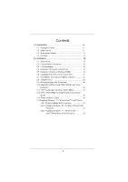
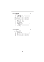
Hard Disks Installation ...30 2.11 Hot Plug Function for SATA / SATAII HDDs ...31 2.12 SATA / SATAII HDD Hot Plug Feature and Operation Guide ...32 2.13 Driver Installation Guide ...34 2.14 Installing Windows® 7 / 7 64-bit / VistaTM / VistaTM 64-bit / XP / XP 64-bit Without RAID Functions ...34 2.14 - ASRock H61DE/SI | User Manual - Page 4
Hardware Health Event Monitoring Screen ...3.6 Boot Screen ...3.7 Security Screen ...3.8 Exit Screen ...4.1 Install Operating System...4.2 Support CD Information ...4.2.1 Running Support CD ...4.2.2 Drivers Menu ...4.2.3 Utilities Menu...4.2.4 Contact Information ...36 36 37 37 38 41 42 44 46 47 48 - ASRock H61DE/SI | User Manual - Page 5
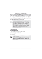
speci c information about the model you are using. www.asrock.com/support/index.asp 1.1 Package Contents ASRock H61DE/SI Motherboard (ATX Form Factor: 12.0-in x 8.6-in, 30.5 cm x 21.8 cm) ASRock H61DE/SI Quick Installation Guide ASRock H61DE/SI Support CD 2 x Serial ATA (SATA) Data Cables (Optional - ASRock H61DE/SI | User Manual - Page 6
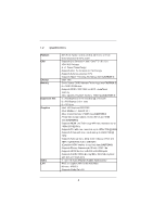
2nd Generation Intel® CoreTM i7 / i5 / i3 in LGA1155 Package - 4 + 1 Power Phase Design - Supports Intel® Turbo Boost 2.0 Technology - Supports K-Series unlocked CPU - Supports Hyper-Threading Technology (see CAUTION 1) - Intel® H61 - Dual Channel DDR3 Memory Technology (see CAUTION 2) - 4 x DDR3 - ASRock H61DE/SI | User Manual - Page 7
AMI UEFI Legal BIOS with GUI support - Supports "Plug and Play" - ACPI 1.1 Compliance Wake Up Events - Supports jumperfree - SMBIOS 2.3.1 Support - IGPU, DRAM, PCH, CPU PLL, VTT, VCCSA Voltage Multi-adjustment - Drivers, Utilities, AntiVirus Software (Trial Version), ASRock Software Suite (CyberLink - ASRock H61DE/SI | User Manual - Page 8
* For detailed product information, please visit our website: http://www.asrock.com WARNING Please realize that there is a certain risk involved with overclocking, including adjusting the setting in the BIOS, applying Untied Overclocking Technology, or using the third-party - ASRock H61DE/SI | User Manual - Page 9
our website for the operation procedures of ASRock Extreme Tuning Utility (AXTU). ASRock website: http://www.asrock.com ASRock Instant Flash is a BIOS ash utility embedded in Flash ROM. This convenient BIOS update tool allows you to update system BIOS without entering operating systems rst like MS - ASRock H61DE/SI | User Manual - Page 10
40% faster than before. ASRock APP Charger allows you to quickly charge many Apple devices simultaneously and even supports continuous charging when your PC enters into Standby mode (S1), Suspend to RAM (S3), hibernation mode (S4) or power off (S5). With APP Charger driver installed, you can easily - ASRock H61DE/SI | User Manual - Page 11
15. Combo Cooler Option (C.C.O.) provides the exible option to adopt three different CPU cooler types, Socket LGA 775, LGA 1155 and LGA 1156. Please be noticed that not all the 775 and 1156 CPU Fan can be used. 16. EuP, stands for Energy Using Product, - ASRock H61DE/SI | User Manual - Page 12
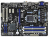
H61DE/SI PCIE1 RoHS CMOS Battery PCI Express 2.0 ErP/EuP Ready 1 HDMI_SPDIF_1 PCIE2 AUDIO CODEC Intel H61 PCI1 1 USB8_9 32Mb BIOS 5 6 7 8 9 10 11 12 13 14 15 1155-Pin CPU Socket CPU Fan Connector (CPU_FAN1) CPU Fan Connector (CPU_FAN2) ATX 12V Power Connector (ATX12V1) 2 x 240-pin DDR3 DIMM - ASRock H61DE/SI | User Manual - Page 13
1.4 I/O Panel 1 2 3 4 5 6 14 1 2 *3 4 5 6 7 7 8 9 13 12 ** 8 9 10 11 12 13 14 11 10 USB 2.0 Ports (USB01) VGA/D-Sub Port LAN RJ-45 Port Central / Bass (Orange) Rear Speaker (Black) Optical SPDIF Out Port Line In (Light Blue) Front Speaker (Lime) Microphone (Pink) USB 2.0 Ports (USB45) USB 2.0 - ASRock H61DE/SI | User Manual - Page 14
To enable Multi-Streaming function, you need to connect a front panel audio cable to the front panel audio header. After restarting your computer, you will nd "Mixer" tool on your system. Please select "Mixer ToolBox" , click "Enable playback multi-streaming", and click "ok". Choose "2CH", "4CH", " - ASRock H61DE/SI | User Manual - Page 15
Chapter 2: Installation This is an ATX form factor (12.0" x 8.6", 30.5 x 21.8 cm) motherboard. Before you install the motherboard, study the con guration of your chassis to ensure that the motherboard ts - ASRock H61DE/SI | User Manual - Page 16
CPU, please follow the steps below. Load Plate Load Lever Contact Array Socket Body 1155-Pin Socket Overview Before you insert the 1155-Pin CPU into the socket, please check if the CPU surface is unclean or PnP cap. 2. This cap must be placed if returning the motherboard for after service. 16 - ASRock H61DE/SI | User Manual - Page 17
Heat Sink) up. Locate Pin1 and the two orientation key notches. orientation key notch Pin1 alignment key Pin1 alignment key orientation key notch 1155-Pin CPU 1155-Pin Socket For proper inserting, please ensure to match the two orientation key notches of the CPU with the two alignment keys of the - ASRock H61DE/SI | User Manual - Page 18
instruction manuals of your CPU fan and heatsink. Below is an example to illustrate the installation of the heatsink for 1155 . Fan cables on side closest to MB header Fastener slots pointing straight out Press Please be noticed that this motherboard supports Combo Cooler Option (C.C.O.), which - ASRock H61DE/SI | User Manual - Page 19
chipset limitation, if you plan to install three or four memory modules on this motherboard, please install only single-sided memory modules. This motherboard supports two double-sided or four single-sided DIMMs. Therefore, if you install four DDR3 DIMMs, you can only adopt four single-sided DIMMs - ASRock H61DE/SI | User Manual - Page 20
Installing a DIMM Please make sure to disconnect power supply before adding or removing DIMMs or the system components. Step 1. Step 2. Unlock a DIMM slot by pressing the retaining clips outward. Align a DIMM on the slot such that the notch on the DIMM matches the break on the slot. notch break - ASRock H61DE/SI | User Manual - Page 21
. Please read the documentation of the expansion card and make necessary hardware settings for the card before you start the installation. Remove the system unit cover (if your motherboard is already installed in a chassis). Remove the bracket facing the slot that you intend to use. Keep the screws - ASRock H61DE/SI | User Manual - Page 22
connect HDMI monitor cable to HDMI port on the I/O panel. VGA/D-Sub port VGA/DVI-D port HDMI port 2. If you have installed onboard VGA driver from our support CD to your system already, you can freely enjoy the bene ts of dual monitor function after your system boots. If you haven't installed - ASRock H61DE/SI | User Manual - Page 23
display upgrade. With the internal VGA output support (DVI-D, D-Sub and HDMI) and external inserted to this motherboard. 4. Install the onboard VGA driver and the add-on PCI Express VGA card driver to your system. If you have installed the drivers already, there is no need to install them again - ASRock H61DE/SI | User Manual - Page 24
function with this motherboard, you need to adopt the monitor that supports HDCP function as well. Therefore, you can enjoy the superior display quality with high-de nition HDCP encryption contents. Please refer to below instruction for more details about HDCP function. What is HDCP? HDCP stands - ASRock H61DE/SI | User Manual - Page 25
need to clear the CMOS when you just nish updating the BIOS, you must boot up the system rst, and then shut it down before you do the clear-CMOS action. Please be noted that the password, date, time, user default pro le, 1394 GUID and MAC address will be cleared only if - ASRock H61DE/SI | User Manual - Page 26
p.12, No. 17) (SATA2_2: see p.12, No. 13) (SATA2_3: see p.12, No. 15) SATA2_1 SATA2_3 SATA2_0 SATA2_2 These four Serial ATAII (SATAII) connectors support SATA data cables for internal storage devices. The current SATAII interface allows up to 3.0 Gb/s data transfer rate. Either end of the SATA data - ASRock H61DE/SI | User Manual - Page 27
. 1. High De nition Audio supports Jack Sensing, but the panel wire on the chassis must support HDA to function correctly. Please follow the instruction in our manual and chassis manual to install your system. 2. state. The LED is off when the system is in S3/S4 sleep state or powered off (S5). 27 - ASRock H61DE/SI | User Manual - Page 28
the CPU fan cable to the connector and match the black wire to the ground pin. Though this motherboard provides 4-Pin CPU fan (Quiet Fan) support, the 3-Pin CPU fan still can work successfully even without the fan speed control function. If you plan to connect the 3-Pin CPU fan to - ASRock H61DE/SI | User Manual - Page 29
supply, please plug your power supply along with Pin 1 and Pin 5. 8 5 4-Pin ATX 12V Power Supply Installation 4 1 Serial port Header (9-pin COM1) (see p.12 No. 22) This COM1 header supports a serial port module. HDMI_SPDIF Header (2-pin HDMI_SPDIF1) (see p.12 No. 27) 1 GND SPDIFOUT HDMI_SPDIF - ASRock H61DE/SI | User Manual - Page 30
) Hard Disks Installation This motherboard adopts Intel® H61 chipset that supports Serial ATA (SATA) / Serial ATAII (SATAII) hard disks. You may install SATA / SATAII hard disks on this motherboard for internal storage devices. This section will guide you to install the SATA / SATAII hard disks - ASRock H61DE/SI | User Manual - Page 31
Hot Plug function for SATA / SATAII in AHCI mode. Intel® H61 chipset provides hardware support for Advanced Host controller Interface (AHCI), a new programming interface for SATA host controllers developed thru a joint industry effort. NOTE What is Hot Plug Function? If the SATA / SATAII HDDs - ASRock H61DE/SI | User Manual - Page 32
is installed into system properly. The latest SATA / SATAII driver is available on our support website: www.asrock.com 4. Make sure to use the SATA power cable & data cable, which are from our motherboard package. 5. Please follow below instructions step by step to reduce the risk of HDD crash or - ASRock H61DE/SI | User Manual - Page 33
the SATA / SATAII HDD. How to Hot Unplug a SATA / SATAII HDD: Points of attention, before you process the Hot Unplug: Please do follow below instruction sequence to process the Hot Unplug, improper procedure will cause the SATA / SATAII HDD damage and data loss. Step 1 Unplug SATA data cable from - ASRock H61DE/SI | User Manual - Page 34
2.13 Driver Installation Guide To install the drivers to your system, please insert the support CD to your optical drive first. Then, the drivers compatible to your system can be auto-detected and listed on the support CD driver page. Please follow the order from up to bottom side to install those - ASRock H61DE/SI | User Manual - Page 35
beginning of Windows® setup, press F6 to install a third-party AHCI driver. When prompted, insert the SATA / SATAII driver diskette containing the Intel® AHCI driver. After reading the floppy disk, the driver will be presented. Select the driver to install according to the mode you choose and the OS - ASRock H61DE/SI | User Manual - Page 36
during the Power-On-Self-Test (POST) to enter the UEFI SETUP UTILITY, otherwise, POST will continue with its test routines. If you wish to enter the then back on. Because the UEFI software is constantly being updated, the following UEFI setup screens and descriptions are for reference purpose - ASRock H61DE/SI | User Manual - Page 37
Screen or exit the current screen 3.2 Main Screen When you enter the UEFI SETUP UTILITY, the Main screen will appear and display the system overview. H61DE/SI 37 - ASRock H61DE/SI | User Manual - Page 38
VistaTM / 7 and want to enable this function, please set this item to [Enabled]. This item will be hidden if the current CPU does not support Intel SpeedStep technology. Please note that enabling this function may reduce CPU voltage and lead to system stability or compatibility issue with some power - ASRock H61DE/SI | User Manual - Page 39
, the motherboard will detect the memory module(s) inserted and assigns appropriate frequency automatically. CAS# Latency (tCL) Use this item to change CAS# Latency (tCL) Auto/Manual setting. The default is [Auto]. RAS# to CAS# Delay (tRCD) Use this item to change RAS# to CAS# Delay (tRCD) Auto - ASRock H61DE/SI | User Manual - Page 40
. The default is [Auto]. ODT WR (CHB) Use this item to change ODT WR (CHB) Auto/Manual setting. The default is [Auto]. ODT NOM (CHB) Use this item to change ODT NOM (CHB) Auto/Manual setting. The default is [Auto]. Voltage Control Power Saving Mode Use this to enable or disable Power - ASRock H61DE/SI | User Manual - Page 41
. Setting wrong values in this section may cause the system to malfunction. ASRock Instant Flash ASRock Instant Flash is a UEFI flash utility embedded in Flash ROM. This convenient UEFI update tool allows you to update system UEFI without entering operating systems rst like MS-DOS or Windows®. Just - ASRock H61DE/SI | User Manual - Page 42
on/off prefetching of adjacent cache lines. Enhance Halt State (C1E) All processors support the Halt State (C1). The C1 state is supported through the native processor instructions HLT and MWAIT and requires no hardware support from the chipset. In the C1 power state, the processor maintains the - ASRock H61DE/SI | User Manual - Page 43
Protection" can prevent data pages from being used by malicious software to execute code. This option will be hidden if the current CPU does not support No-Excute Memory Protection. Local x2APIC Use this to enable or disable Local x2APIC. The default value is [Disabled]. Please be noted that some OS - ASRock H61DE/SI | User Manual - Page 44
) is an architecture that offers breakthrough performance for the motherboard through ef cient memory utilization. In DVMT mode, the graphics driver allocates memory as needed for running graphics applications and is cooperatively using this memory with other system components. This item will - ASRock H61DE/SI | User Manual - Page 45
DVMT Memory You are allowed to adjust the shared memory size in this item. Configuration options: [128MB], [256MB] and [Maximum]. The option [Maximum] only appears when you adopt the memory module with 1024MB or above. 45 - ASRock H61DE/SI | User Manual - Page 46
] is selected, the AC/power resumes and the system starts to boot up when the power recovers. Deep Sx Mobile platforms support Deep S4/S5 in DC only and desktop platforms support Deep S4/S5 in AC only. Con guration options: [Disabled], [Enabled in S5] and [Enabled in S4 and S5]. The - ASRock H61DE/SI | User Manual - Page 47
SATA mode. Con guration options: [IDE Mode], [AHCI Mode] and [Disabled]. The default value is [IDE Mode]. AHCI (Advanced Host Controller Interface) supports NCQ and other new features that will improve SATA disk performance but IDE mode does not have these advantages. SATA Controller 0 Please select - ASRock H61DE/SI | User Manual - Page 48
3.4.5 Super IO Configuration Serial Port Use this item to enable or disable the onboard serial port. Serial Port Address Use this item to set the address for the onboard serial port. Con guration options: [3F8 / IRQ4] and [3E8 / IRQ4]. Infrared Port Use this item to enable or disable the onboard - ASRock H61DE/SI | User Manual - Page 49
RAM Use this item to select whether to auto-detect or disable the Suspend-toRAM feature. Select [Auto] will enable this feature if the OS supports it. Check Ready Bit Use this item to enable or disable the feature Check Ready Bit. PS/2 Keyboard Power On Use this item to enable - ASRock H61DE/SI | User Manual - Page 50
]. The default value is [Enabled]. Please refer to below descriptions for the details of these four options: [Enabled] - Enables support for legacy USB. [Auto] - Enables legacy support if USB devices are connected. [Disabled] - USB devices are not allowed to use under legacy OS and UEFI setup when - ASRock H61DE/SI | User Manual - Page 51
3.5 Hardware Health Event Monitoring Screen In this section, it allows you to monitor the status of the hardware on your system, including the parameters of the CPU temperature, motherboard temperature, CPU fan speed, chassis fan speed, and the critical voltage. CPU Fan 1 & 2 Setting This allows - ASRock H61DE/SI | User Manual - Page 52
3.6 Boot Screen In this section, it will display the available devices on your system for you to con gure the boot settings and the boot priority. Setup Prompt Timeout This shows the number of seconds to wait for setup activation key. 65535(0XFFFF) means inde nite waiting. Bootup Num-Lock If this - ASRock H61DE/SI | User Manual - Page 53
3.7 Security Screen In this section, you may set or change the supervisor/user password for the system. For the user password, you may also clear it. 53 - ASRock H61DE/SI | User Manual - Page 54
3.8 Exit Screen Save Changes and Exit When you select this option, it will pop-out the following message, "Save con guration changes and exit setup?" Select [OK] to save the changes and exit the UEFI SETUP UTILITY. Discard Changes and Exit When you select this option, it will pop-out the following - ASRock H61DE/SI | User Manual - Page 55
install the necessary drivers to activate the devices. 4.2.3 Utilities Menu The Utilities Menu shows the applications software that the motherboard supports. Click on a speci c item then follow the installation wizard to install it. 4.2.4 Contact Information If you need to contact ASRock or want - ASRock H61DE/SI | User Manual - Page 56
OS on a HDD Larger Than 2TB This motherboard is adopting UEFI BIOS that allows Windows® OS to be installed on a large size HDD you install Windows® 7 64-bit OS, OS will be formatted by GPT (GUID Partition Table). Please install the hot x le from Microsoft®: http://support.microsoft.com/kb/979903 56
-
 1
1 -
 2
2 -
 3
3 -
 4
4 -
 5
5 -
 6
6 -
 7
7 -
8
-
9
-
10
-
11
-
12
-
13
-
14
-
15
-
16
-
17
-
18
-
19
-
20
-
21
-
22
-
23
-
24
-
25
-
26
-
27
-
28
-
29
-
30
-
31
-
32
-
33
-
34
-
35
-
36
-
37
-
38
-
39
-
40
-
41
-
42
-
43
-
44
-
45
-
46
-
47
-
48
-
49
-
50
-
51
-
52
-
53
-
54
-
55
-
56
 |
 |
1
H61DE/SI
User Manual
Version 1.0
Published February 2011
Copyright©2011 ASRock INC. All rights reserved.