ASRock H61M-DGS User Manual
ASRock H61M-DGS Manual
 |
View all ASRock H61M-DGS manuals
Add to My Manuals
Save this manual to your list of manuals |
ASRock H61M-DGS manual content summary:
- ASRock H61M-DGS | User Manual - Page 1
H61M-DGS User Manual Version 1.0 Published December 2011 Copyright©2011 ASRock INC. All rights reserved. 1 - ASRock H61M-DGS | User Manual - Page 2
purchaser for backup purpose, without written consent of ASRock Inc. Products and corporate names appearing in this manual may or may not be registered trademarks or copyrights , USA ONLY The Lithium battery adopted on this motherboard contains Perchlorate, a toxic substance controlled in Perchlorate - ASRock H61M-DGS | User Manual - Page 3
23 2.9 Onboard Headers and Connectors 24 2.10 Serial ATA (SATA) / Serial ATAII (SATAII) Hard Disks Installation 28 2.11 Hot Plug Function for SATA / SATAII HDDs 28 2.12 SATA / SATAII HDD Hot Plug Feature and Operation Guide 29 2.13 Driver Installation Guide 31 2.14 Installing Windows® 7 / 7 64 - ASRock H61M-DGS | User Manual - Page 4
ACPI Configuration 46 3.4.7 USB Configuration 47 3.5 Hardware Health Event Monitoring Screen 48 3.6 Boot Screen 49 3.7 Security Screen 50 3.8 Exit Screen 51 4 Software Support 52 4.1 Install Operating System 52 4.2 Support CD Information 52 4.2.1 Running Support CD 52 4.2.2 Drivers Menu 52 - ASRock H61M-DGS | User Manual - Page 5
fic information about the model you are using. www.asrock.com/support/index.asp 1.1 Package Contents ASRock H61M-DGS Motherboard (Micro ATX Form Factor: 8.9-in x 6.8-in, 22.6 cm x 17.3 cm) ASRock H61M-DGS Quick Installation Guide ASRock H61M-DGS Support CD 2 x Serial ATA (SATA) Data Cables (Optional - ASRock H61M-DGS | User Manual - Page 6
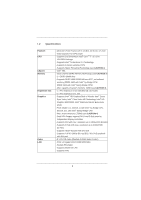
CPU Chipset Memory Expansion Slot Graphics Audio LAN - Micro ATX Form Factor: 8.9-in x 6.8-in, 22.6 cm x 17.3 cm - Solid Capacitor for CPU power - Supports 2nd Generation Intel® CoreTM i7 / i5 / i3 in LGA1155 Package - Supports Intel® Turbo Boost 2.0 Technology - Supports K-Series unlocked CPU - ASRock H61M-DGS | User Manual - Page 7
x Print Port header - 1 x COM port header - CPU/Chassis/Power FAN connector - 24 pin ATX power connector - 4 pin 12V power connector - Front panel audio connector - 2 x USB 2.0 headers (support 4 USB 2.0 ports) - 32Mb AMI BIOS - AMI UEFI Legal BIOS with GUI support - Supports "Plug and Play" - ACPI - ASRock H61M-DGS | User Manual - Page 8
visit our website: http://www.asrock.com WARNING Please realize that there is a certain risk involved with overclocking, including adjusting the setting in the BIOS, applying Untied Overclocking Technology, or using the third-party overclocking tools. Overclocking may affect your system stability - ASRock H61M-DGS | User Manual - Page 9
VistaTM / XP. For Windows® OS with 64-bit CPU, there is no such limitation. You can use ASRock XFast RAM to utilize the memory that Windows® cannot use. 4. The maximum shared memory size is defined by the chipset vendor and is subject to change. Please check Intel® website for the latest information - ASRock H61M-DGS | User Manual - Page 10
the latency in game. Traffic Shaping: You can watch Youtube HD video and download files simultaneously. Real-Time Analysis of Your Data: With the status window, you can easily recognize which data streams you are currently transferring. 11. ASRock XFast RAM fully utilizes the memory space that cannot - ASRock H61M-DGS | User Manual - Page 11
14. ASRock XFast RAM is not supported by Microsoft® Windows® XP / XP 64-bit. 15. EuP, stands for in off mode condition. To meet EuP standard, an EuP ready motherboard and an EuP ready power supply are required. According to Intel's suggestion, the EuP ready power supply must meet the standard of - ASRock H61M-DGS | User Manual - Page 12
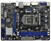
19 18 17 16 15 14 13 12 11 10 9 1 1155-Pin CPU Socket 2 ATX 12V Power Connector (ATX12V1) 3 CPU Fan Connector (CPU_FAN1) 4 ATX Power Connector (ATXPWR1) 5 2 x 240-pin DDR3 DIMM Slots (Dual Channel: DDR3_A1, DDR3_B1, Blue) 6 Intel H61 Chipset 7 32Mb SPI Flash 8 SATA2 Connector (SATA2_1, Blue - ASRock H61M-DGS | User Manual - Page 13
5 Microphone (Pink) 6 USB 2.0 Ports (USB45) 7 USB 2.0 Ports (USB23) 8 USB 2.0 Ports (USB01) 9 DVI-D Port 10 D-Sub Port 11 PS/2 Audio 2nd output" to use front panel audio. Then reboot your system. For Windows® 7 / VistaTM: After restarting your computer, please double-click "Realtek HD Audio - ASRock H61M-DGS | User Manual - Page 14
This is a Micro ATX form factor (8.9" x 6.8", 22.6 x 17.3 cm) motherboard. Before you install the motherboard, study the configuration of your chassis to ensure that the motherboard fits into it. Make sure to unplug the power cord before installing or removing the motherboard. Failure to do - ASRock H61M-DGS | User Manual - Page 15
of Intel 1155-Pin CPU, please follow the steps below. Load Plate Load Lever Contact Array Socket Body 1155-Pin Socket Overview Before you insert the 1155-Pin CPU into the socket, please check if the CPU the PnP cap. 2. This cap must be placed if returning the motherboard for after service. 15 - ASRock H61M-DGS | User Manual - Page 16
key notches. orientation key notch alignment key Pin1 Pin1 orientation key notch 1155-Pin CPU alignment key 1155-Pin Socket For proper inserting, please ensure to match the two orientation key notches of the CPU with the two alignment keys of the socket. Step 3-3. Carefully place the - ASRock H61M-DGS | User Manual - Page 17
operation or contact other components. Please be noticed that this motherboard supports Combo Cooler Option (C.C.O.), which provides the flexible option to adopt three different CPU cooler types, Socket LGA 775, LGA 1155 and LGA 1156. The white throughholes are for Socket LGA 1155/1156 CPU fan. 17 - ASRock H61M-DGS | User Manual - Page 18
2.5 Installation of Memory Modules (DIMM) This motherboard provides two 240-pin DDR3 (Double Data Rate 3) DIMM slots, and supports Dual Channel Memory Technology. For dual channel configuration, you always need to install two identical (the same brand, speed, size and chiptype) memory modules in the - ASRock H61M-DGS | User Manual - Page 19
Express slots on this motherboard. PCIE slots: PCIE1 (PCIE x16 slot; Blue) is used for PCI Express x16 lane width graphics cards. PCIE2 (PCIE x1 slot; White) is used for PCI Express cards with x1 lane width cards, such as Gigabit LAN card, SATA2 card, etc. Installing an expansion card Step 1. Before - ASRock H61M-DGS | User Manual - Page 20
motherboard supports dual monitor feature. With the internal VGA output support (DVI-D and D-Sub), you can easily enjoy the benefits of dual monitor feature without installing any add-on VGA card to this motherboard. This motherboard you have installed onboard VGA driver from our support CD to your - ASRock H61M-DGS | User Manual - Page 21
. If you do not adjust the UEFI setup, the default value of "Onboard VGA Share Memory", [Auto], will disable D-Sub function when the add-on VGA card is inserted to this motherboard. 4. Install the onboard VGA driver and the add-on PCI Express VGA card driver to your system. If you have installed the - ASRock H61M-DGS | User Manual - Page 22
supported on this motherboard. To use HDCP function with this motherboard, you need to adopt the monitor that supports HDCP function as well. Therefore, you can enjoy the superior display quality with high-definition HDCP encryption contents. Please refer to below instruction Products compatible with - ASRock H61M-DGS | User Manual - Page 23
to clear the CMOS when you just finish updating the BIOS, you must boot up the system first, and then shut it down before you do the clear-CMOS action. Please be noted that the password, date, time, user default profile, 1394 GUID and MAC address will be cleared only if the - ASRock H61M-DGS | User Manual - Page 24
support SATA data cables for internal storage devices. The current SATAII interface allows up to 3.0 Gb/s data transfer rate. Serial ATA (SATA) Data Cable (Optional) Either end of the SATA data cable can be connected to the SATA / SATAII hard disk or the SATAII connector on this motherboard. USB - ASRock H61M-DGS | User Manual - Page 25
cable that allows convenient connection and control of audio devices. 1. High Definition Audio supports Jack Sensing, but the panel wire on the chassis must support HDA to function correctly. Please follow the instruction in our manual and chassis manual to install your system. 2. If you use AC - ASRock H61M-DGS | User Manual - Page 26
fan (Quiet Fan) support, the 3-Pin CPU fan still can work successfully even without the fan speed control function. If you plan to connect the 3-Pin CPU fan to the CPU fan connector on this motherboard, please connect it to Pin 1-3. Pin 1-3 Connected 3-Pin Fan Installation ATX Power Connector (24 - ASRock H61M-DGS | User Manual - Page 27
Though this motherboard provides 24-pin ATX power connector, 12 24 it can still work if you adopt a traditional 20-pin ATX power supply. To use the 20-pin ATX power supply, please plug your power supply along with Pin 1 and Pin 13. ATX 12V Power Connector (4-pin ATX12V1) (see p.12 No. 2) Serial - ASRock H61M-DGS | User Manual - Page 28
2.10 Serial ATA (SATA) / Serial ATAII (SATAII) Hard Disks Installation This motherboard adopts Intel® H61 chipset that supports Serial ATA (SATA) / Serial ATAII (SATAII) hard disks. You may install SATA / SATAII hard disks on this motherboard for internal storage devices. This section will guide you - ASRock H61M-DGS | User Manual - Page 29
not be supported by the chipset because of its limitation, the SATA / SATAII Hot Plug support information of our motherboard is indicated in the product spec on our website: www.asrock.com 2. Make sure your SATA / SATAII HDD can support Hot Plug function from your dealer or HDD user manual. The SATA - ASRock H61M-DGS | User Manual - Page 30
cable to (White) to the power supply 1x4-pin cable. the motherboard's SATAII connector. SATA power cable 1x4-pin power connector (White) Step attention, before you process the Hot Unplug: Please do follow below instruction sequence to process the Hot Unplug, improper procedure will cause the SATA - ASRock H61M-DGS | User Manual - Page 31
2.13 Driver Installation Guide To install the drivers to your system, please insert the support CD to your optical drive first. Then, the drivers compatible to your system can be auto-detected and listed on the support CD driver page. Please follow the order from up to bottom side to install those - ASRock H61M-DGS | User Manual - Page 32
on your system. At the beginning of Windows® setup, press F6 to install a third-party AHCI driver. When prompted, insert the SATA / SATAII driver diskette containing the Intel® AHCI driver. After reading the floppy disk, the driver will be presented. Select the driver to install according to the mode - ASRock H61M-DGS | User Manual - Page 33
configure your system. The UEFI chip on the motherboard stores the UEFI SETUP UTILITY. You may run the Because the UEFI software is constantly being updated, the following UEFI setup screens and descriptions /date information OC Tweaker To set up overclocking features Advanced To set up the advanced UEFI - ASRock H61M-DGS | User Manual - Page 34
3.1.2 Navigation Keys Please check the following table for the function description of each navigation key. Navigation Key(s) Function Description / Moves cursor left or right to select Screens / Moves cursor up or down to select items + / - To change option for the selected items - ASRock H61M-DGS | User Manual - Page 35
overclocking may cause damage to your CPU and motherboard. It should be done at your own risk and expense. CPU Configuration CPU Ratio Use this item to change the ratio value of this motherboard. Intel SpeedStep Technology Intel SpeedStep technology is Intel's new power saving technology. Processors - ASRock H61M-DGS | User Manual - Page 36
Use this item to configure time window which the long duration power is maintained. OverClocking Support Use this item to enable or disable GT OverClocking Support. The default value is [Disabled]. DRAM Timing Configuration DRAM Frequency If [Auto] is selected, the motherboard will detect the memory - ASRock H61M-DGS | User Manual - Page 37
setting. The default is [Auto]. DRAM tRTP Use this item to change Read to Precharge (tRTP) Auto/Manual setting. The default is [Auto]. DRAM tFAW Use this item to change Four Activate Window (tFAW) Auto/Manual setting. The default is [Auto]. DRAM tCWL Use this item to change CAS# Write Latency (tCWL - ASRock H61M-DGS | User Manual - Page 38
Voltage Offset Use this to select CPU Core Voltage Offset. The default value is [Auto]. IGPU Auto]. PCH Voltage Use this to select PCH Voltage. The default value is [Auto]. CPU PLL Voltage Use this to select CPU PLL Voltage. The default value is [Auto]. VCCSA Voltage Use this to select VCCSA Voltage - ASRock H61M-DGS | User Manual - Page 39
CPU Configuration, North Bridge Configuration, South Bridge Configuration, Storage Configuration, Super IO Configuration, ACPI Configuration and USB UEFI update tool allows you to update system UEFI without entering operating systems first like MS-DOS or Windows®. Just save the new UEFI file to your USB fl - ASRock H61M-DGS | User Manual - Page 40
(C1). The C1 state is supported through the native processor instructions HLT and MWAIT and requires no hardware support from the chipset. In the C1 power state, the processor maintains the context of the system caches. CPU C3 State Support Use this to enable or disable CPU C3 (ACPI C2) report to - ASRock H61M-DGS | User Manual - Page 41
to the IA-32 Intel Architecture. An IA-32 processor with "No Execute (NX) Memory Protection" can prevent data pages from being used by malicious software to execute codes. This option will be hidden if the current CPU does not support No-Excute Memory Protection. Intel Virtualization Technology When - ASRock H61M-DGS | User Manual - Page 42
is [Disabled]. Share Memory This allows you to set onboard VGA share memory feature. The default value is [Auto]. Configuration options: [Auto], [32MB], [64MB], [128MB], [256MB] and [512MB]. IGD Multi-Monitor Use this to enable or disable IGD Multi-Monitor by Internal Graphics Device. The default - ASRock H61M-DGS | User Manual - Page 43
South Bridge Configuration Onboard HD Audio Select [Auto], [Enabled] or [Disabled] for the onboard HD Audio feature. If you select [Auto], the onboard HD Audio will be disabled when PCI Sound Card is plugged. Front Panel Select [Auto] or [Disabled] for the onboard HD Audio Front Panel. Onboard HDMI - ASRock H61M-DGS | User Manual - Page 44
SATA mode. Configuration options: [IDE Mode], [AHCI Mode] and [Disabled]. The default value is [IDE Mode]. AHCI (Advanced Host Controller Interface) supports NCQ and other new features that will improve SATA disk performance but IDE mode does not have these advantages. Hard Disk S.M.A.R.T. Use this - ASRock H61M-DGS | User Manual - Page 45
serial port. Serial Port Address Use this item to set the address for the onboard serial port. Configuration options: [3F8 / IRQ4] and [3E8 / IRQ4]. Parallel Port Use this item to enable or disable the onboard parallel port. Device Mode Use this item to change the Printer Port mode. Change Settings - ASRock H61M-DGS | User Manual - Page 46
[Auto] will enable this feature if the OS supports it. Check Ready Bit Use this item to to [Enabled] if you plan to use this motherboard to submit Windows® VistaTM certification. PS/2 Keyboard Power On system. USB Keyboard/Remote Power On Use this item to enable or disable USB Keyboard/Remote to - ASRock H61M-DGS | User Manual - Page 47
these four options: [Enabled] - Enables support for legacy USB. [Auto] - Enables legacy support if USB devices are connected. [Disabled] - USB devices are not allowed to use under legacy OS and UEFI setup when [Disabled] is selected. If you have USB compatibility issue, it is recommended to select - ASRock H61M-DGS | User Manual - Page 48
the status of the hardware on your system, including the parameters of the CPU temperature, motherboard temperature, CPU fan speed, chassis fan speed, and the critical voltage. CPU Fan Setting This allows you to set the CPU fan speed. Configuration options: [Full On] and [Automatic Mode]. The default - ASRock H61M-DGS | User Manual - Page 49
boots, please select [Enabled]. Configuration options: [Enabled] and [Disabled]. The default value is [Enabled]. Boot From Onboard LAN Use this item to enable or disable the Boot From Onboard LAN feature. Boot Failure Guard Enable or disable the feature of Boot Failure Guard. Boot Failure Guard Count - ASRock H61M-DGS | User Manual - Page 50
3.7 Security Screen In this section, you may set or change the supervisor/user password for the system. For the user password, you may also clear it. 50 - ASRock H61M-DGS | User Manual - Page 51
3.8 Exit Screen Save Changes and Exit When you select this option, it will pop-out the following message, "Save configuration changes and exit setup?" Select [OK] to save the changes and exit the UEFI SETUP UTILITY. Discard Changes and Exit When you select this option, it will pop-out the following - ASRock H61M-DGS | User Manual - Page 52
install the necessary drivers to activate the devices. 4.2.3 Utilities Menu The Utilities Menu shows the applications software that the motherboard supports. Click on a specific item then follow the installation wizard to install it. 4.2.4 Contact Information If you need to contact ASRock or want to - ASRock H61M-DGS | User Manual - Page 53
HDD Larger Than 2TB This motherboard is adopting UEFI BIOS that allows Windows® OS to be installed on a large size HDD (>2TB). Please follow below procedure to install the operating system. 1. Please make sure to use Windows® VistaTM 64-bit (with SP1 or above) or Windows® 7 64-bit. 2. Press or
-
 1
1 -
 2
2 -
 3
3 -
 4
4 -
 5
5 -
 6
6 -
 7
7 -
8
-
9
-
10
-
11
-
12
-
13
-
14
-
15
-
16
-
17
-
18
-
19
-
20
-
21
-
22
-
23
-
24
-
25
-
26
-
27
-
28
-
29
-
30
-
31
-
32
-
33
-
34
-
35
-
36
-
37
-
38
-
39
-
40
-
41
-
42
-
43
-
44
-
45
-
46
-
47
-
48
-
49
-
50
-
51
-
52
-
53
 |
 |

1
H61M-DGS
User Manual
Version 1.0
Published December 2011
Copyright©2011 ASRock INC. All rights reserved.