ASRock H61M-DS User Manual
ASRock H61M-DS Manual
 |
View all ASRock H61M-DS manuals
Add to My Manuals
Save this manual to your list of manuals |
ASRock H61M-DS manual content summary:
- ASRock H61M-DS | User Manual - Page 1
H61M-VGS / H61M-VS User Manual Version 1.0 Published February 2011 Copyright©2011 ASRock INC. All rights reserved. 1 - ASRock H61M-DS | User Manual - Page 2
that may appear in this manual. With respect to the contents of this manual, ASRock does not provide warranty of any kind, either expressed or implied, including but CALIFORNIA, USA ONLY The Lithium battery adopted on this motherboard contains Perchlorate, a toxic substance controlled in Perchlorate - ASRock H61M-DS | User Manual - Page 3
/ H61M-VS 11 1.4 I/O Panel (H61M-VGS 12 1.5 I/O Panel (H61M-VS 13 2 Installation 14 2.1 Screw Holes 14 2.2 Pre-installation Precautions 14 2.3 CPU Installation 15 2.4 Installation of Heatsink and CPU fan 17 2.5 Installation of Memory Modules (DIMM 18 2.6 Expansion Slots (PCI Express Slots - ASRock H61M-DS | User Manual - Page 4
Main Screen 33 3.3 OC Tweaker Screen 35 3.4 Advanced Screen 38 3.4.1 CPU Configuration 39 3.4.2 North Bridge Configuration 41 3.4.3 South Bridge Confi 51 4 Software Support 52 4.1 Install Operating System 52 4.2 Support CD Information 52 4.2.1 Running Support CD 52 4.2.2 Drivers Menu 52 4.2.3 - ASRock H61M-DS | User Manual - Page 5
-VGS / H61M-VS Motherboard (Micro ATX Form Factor: 8.9-in x 6.8-in, 22.6 cm x 17.3 cm) ASRock H61M-VGS / H61M-VS Quick Installation Guide ASRock H61M-VGS / H61M-VS Support CD 2 x Serial ATA (SATA) Data Cables (Optional) 1 x I/O Panel Shield ASRock Reminds You... To get better performance in Windows - ASRock H61M-DS | User Manual - Page 6
1 x PCI Express 2.0 x16 slot (blue @ x16 mode) - 1 x PCI Express 2.0 x1 slot - Intel® HD Graphics 2000/3000 - Pixel Shader 4.1, DirectX 10.1 - Max. shared memory 1759MB (see CAUTION 4) - Supports D-Sub with max. resolution up to 2048x1536 @ 75Hz - 5.1 CH HD Audio (VIA® VT1705 Audio Codec) - H61M-VGS - ASRock H61M-DS | User Manual - Page 7
1 x COM port header - CPU/Chassis/Power FAN connector - 24 pin ATX power connector - 4 pin 12V power connector - Front panel audio connector - 2 x USB 2.0 headers (support 4 USB 2.0 ports) BIOS Feature - 32Mb AMI BIOS - AMI UEFI Legal BIOS with GUI support - Supports "Plug and Play" - ACPI - ASRock H61M-DS | User Manual - Page 8
for system usage under Windows® 7 / VistaTM / XP. For Windows® OS with 64-bit CPU, there is no such limitation. 4. The maximum shared memory size is defined by the chipset vendor and is subject to change. Please check Intel® website for the latest information. 5. ASRock Extreme Tuning Utility (AXTU - ASRock H61M-DS | User Manual - Page 9
joystick to control your PC games. All you have to do is just to install the ASRock AIWI utility either from ASRock official website or ASRock software support CD to your motherboard, and also download the free AIWI Lite from App store to your iPhone/iPod touch. Connecting your PC and apple devices - ASRock H61M-DS | User Manual - Page 10
power of the completed system shall be under 1.00W in off mode condition. To meet EuP standard, an EuP ready motherboard and an EuP ready power supply are required. According to Intel's suggestion, the EuP ready power supply must meet the standard of 5v standby power efficiency is higher than 50 - ASRock H61M-DS | User Manual - Page 11
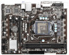
18 17 16 15 14 13 12 11 10 9 1 1155-Pin CPU Socket 2 ATX 12V Power Connector (ATX12V1) 3 CPU Fan Connector (CPU_FAN1) 4 ATX Power Connector (ATXPWR1) 5 2 x 240-pin DDR3 DIMM Slots (Dual Channel: DDR3_A1, DDR3_B1, Blue) 6 Intel H61 Chipset 7 32Mb SPI Flash 8 SATA2 Connector (SATA2_1, Blue - ASRock H61M-DS | User Manual - Page 12
header. After restarting your computer, you will find "VIA HD Audio Deck" tool on your system. Please follow below instructions according to the OS you install. For Windows® XP / XP 64-bit OS: Please click "VIA HD Audio Deck" icon , and click "Speaker". Then you are allowed to select "2 Channel - ASRock H61M-DS | User Manual - Page 13
header. After restarting your computer, you will find "VIA HD Audio Deck" tool on your system. Please follow below instructions according to the OS you install. For Windows® XP / XP 64-bit OS: Please click "VIA HD Audio Deck" icon , and click "Speaker". Then you are allowed to select "2 Channel - ASRock H61M-DS | User Manual - Page 14
This is a Micro ATX form factor (8.9" x 6.8", 22.6 x 17.3 cm) motherboard. Before you install the motherboard, study the configuration of your chassis to ensure that the motherboard fits into it. Make sure to unplug the power cord before installing or removing the motherboard. Failure to do - ASRock H61M-DS | User Manual - Page 15
of Intel 1155-Pin CPU, please follow the steps below. Load Plate Load Lever Contact Array Socket Body 1155-Pin Socket Overview Before you insert the 1155-Pin CPU into the socket, please check if the CPU the PnP cap. 2. This cap must be placed if returning the motherboard for after service. 15 - ASRock H61M-DS | User Manual - Page 16
key notches. orientation key notch alignment key Pin1 Pin1 orientation key notch 1155-Pin CPU alignment key 1155-Pin Socket For proper inserting, please ensure to match the two orientation key notches of the CPU with the two alignment keys of the socket. Step 3-3. Carefully place the - ASRock H61M-DS | User Manual - Page 17
Heatsink This motherboard is equipped with 1155-Pin socket that supports Intel 1155-Pin CPU. Please adopt the type of heatsink and cooling fan compliant with Intel 1155Pin CPU to dissipate heat. Before you installed the heatsink, you need to spray thermal interface material between the CPU and the - ASRock H61M-DS | User Manual - Page 18
of Memory Modules (DIMM) This motherboard provides two 240-pin DDR3 (Double Data Rate 3) DIMM slots, and supports Dual Channel Memory Technology. For dual channel configuration, you always need to install two identical (the same brand, speed, size and chiptype) memory modules in the DDR3 DIMM - ASRock H61M-DS | User Manual - Page 19
Slots (PCI Express Slots) There are 2 PCI Express slots on this motherboard. PCIE slots: PCIE1 (PCIE x16 slot; Blue) is used for PCI Express x16 lane width graphics cards. PCIE2 (PCIE x1 slot; White) is used for PCI Express cards with x1 lane width cards, such as Gigabit LAN card, SATA2 card, etc - ASRock H61M-DS | User Manual - Page 20
when the add-on VGA card is inserted to this motherboard. 4. Install the onboard VGA driver and the add-on PCI Express VGA card driver to your system. If you have installed the drivers already, there is no need to install them again. 5. Set up a multi-monitor display. For Windows® XP / XP 64-bit OS - ASRock H61M-DS | User Manual - Page 21
"Apply" or "OK" to apply these new values. G. Repeat steps C through E for the diaplay icon identified by the number one, two and three. For Windows® 7 / 7 64-bit / VistaTM / VistaTM 64-bit OS: Right click the desktop, choose "Personalize", and select the "Display Settings" tab so that you can adjust - ASRock H61M-DS | User Manual - Page 22
need to clear the CMOS when you just finish updating the BIOS, you must boot up the system first, and then shut it down before you do the clear-CMOS action. Please be noted that the password, date, time, user default profile, 1394 GUID and MAC address will be cleared only if the - ASRock H61M-DS | User Manual - Page 23
and connectors will cause permanent damage of the motherboard! Serial ATAII Connectors (SATA2_0: see p.11, No. 10) (SATA2_1: see p.11, No. 8) on the I/O panel, there are two USB 2.0 headers on this motherboard. Each USB 2.0 header can support two USB 2.0 ports. Print Port Header (25-pin LPT1) (see - ASRock H61M-DS | User Manual - Page 24
cable that allows convenient connection and control of audio devices. 1. High Definition Audio supports Jack Sensing, but the panel wire on the chassis must support HDA to function correctly. Please follow the instruction in our manual and chassis manual to install your system. 2. If you use AC - ASRock H61M-DS | User Manual - Page 25
fan (Quiet Fan) support, the 3-Pin CPU fan still can work successfully even without the fan speed control function. If you plan to connect the 3-Pin CPU fan to the CPU fan connector on this motherboard, please connect it to Pin 1-3. Pin 1-3 Connected 3-Pin Fan Installation ATX Power Connector (24 - ASRock H61M-DS | User Manual - Page 26
ATX 12V Power Connector (4-pin ATX12V1) (see p.11 No. 2) Serial port Header (9-pin COM1) (see p.11 No. 17) Please connect an ATX 12V power supply to this connector. This COM1 header supports a serial port module. 26 - ASRock H61M-DS | User Manual - Page 27
2.10 Serial ATA (SATA) / Serial ATAII (SATAII) Hard Disks Installation This motherboard adopts Intel® H61 chipset that supports Serial ATA (SATA) / Serial ATAII (SATAII) hard disks. You may install SATA / SATAII hard disks on this motherboard for internal storage devices. This section will guide you - ASRock H61M-DS | User Manual - Page 28
not be supported by the chipset because of its limitation, the SATA / SATAII Hot Plug support information of our motherboard is indicated in the product spec on our website: www.asrock.com 2. Make sure your SATA / SATAII HDD can support Hot Plug function from your dealer or HDD user manual. The SATA - ASRock H61M-DS | User Manual - Page 29
the power supply 1x4-pin cable. Connect SATA data cable to the motherboard's SATAII connector. SATA power cable 1x4-pin power connector (White) attention, before you process the Hot Unplug: Please do follow below instruction sequence to process the Hot Unplug, improper procedure will cause the - ASRock H61M-DS | User Manual - Page 30
to your system can be auto-detected and listed on the support CD driver page. Please follow the order from up to bottom side to install those required drivers. Therefore, the drivers you install can work properly. 2.14 Installing Windows® 7 / 7 64-bit / VistaTM / VistaTM 64-bit / XP / XP 64-bit - ASRock H61M-DS | User Manual - Page 31
on your system. At the beginning of Windows® setup, press F6 to install a third-party AHCI driver. When prompted, insert the SATA / SATAII driver diskette containing the Intel® AHCI driver. After reading the floppy disk, the driver will be presented. Select the driver to install according to the mode - ASRock H61M-DS | User Manual - Page 32
configure your system. The UEFI chip on the motherboard stores the UEFI SETUP UTILITY. You may run the Because the UEFI software is constantly being updated, the following UEFI setup screens and descriptions /date information OC Tweaker To set up overclocking features Advanced To set up the advanced UEFI - ASRock H61M-DS | User Manual - Page 33
Screen or exit the current screen 3.2 Main Screen When you enter the UEFI SETUP UTILITY, the Main screen will appear and display the system overview. H61M-VGS 33 - ASRock H61M-DS | User Manual - Page 34
H61M-VS 34 - ASRock H61M-DS | User Manual - Page 35
. Please note that overclocking may cause damage to your GPU and motherboard. It should be done at your own risk and expense. CPU Ratio Setting Use this item to change the ratio value of this motherboard. GT Over Clock Use this to enable or disable GT Over Clock by Internal Graphics Device. The - ASRock H61M-DS | User Manual - Page 36
. Configuration options: [Auto] and [Manual]. The default value is [Auto]. Core Current Limit Use this item to add voltage when CPU is in Turbo mode. DRAM Timing Control DRAM Frequency If [Auto] is selected, the motherboard will detect the memory module(s) inserted and assigns appropriate frequency - ASRock H61M-DS | User Manual - Page 37
Use this item to change Four Activate Window (tFAW) Auto/Manual setting. The default is [Auto]. Memory Power Down Mode Use this item to Use this to select PCH Voltage. The default value is [Auto]. CPU PLL Voltage Use this to select CPU PLL Voltage. The default value is [Auto]. VTT Voltage Use this - ASRock H61M-DS | User Manual - Page 38
configurations for the following items: CPU Configuration, North Bridge Configuration ASRock Instant Flash ASRock Instant Flash is a UEFI flash utility embedded in Flash ROM. This convenient UEFI update tool allows you to update system UEFI without entering operating systems first like MS-DOS or Windows - ASRock H61M-DS | User Manual - Page 39
(C1). The C1 state is supported through the native processor instructions HLT and MWAIT and requires no hardware support from the chipset. In the C1 power state, the processor maintains the context of the system caches. CPU C3 State Support Use this to enable or disable CPU C3 (ACPI C2) report to - ASRock H61M-DS | User Manual - Page 40
provided by Vanderpool Technology. This option will be hidden if the installed CPU does not support Intel Virtualization Technology. No-Excute Memory Protection No-Execution (NX) Memory Protection Technology is an enhancement to the IA-32 Intel Architecture. An IA-32 processor with "No Execute (NX - ASRock H61M-DS | User Manual - Page 41
(Intel® Virtualization Technology for Directed I/O). The default value of this feature is [Disabled]. Primary Graphics Adapter This allows you to select the boot graphic adapter priority. Configuration options: [Onboard] and [PCI Express]. The default value is [PCI Express]. Onboard VGA Share Memory - ASRock H61M-DS | User Manual - Page 42
DVMT Memory You are allowed to adjust the shared memory size in this item. Configuration options: [128MB], [256MB] and [Maximum]. The option [Maximum] only appears when you adopt the memory module with 1024MB or above. 42 - ASRock H61M-DS | User Manual - Page 43
allows you to enable or disable the "Onboard LAN" feature. Onboard HD Audio Select [Auto], [Enabled] or [Disabled] for the onboard HD Audio feature. If you select [Auto], the onboard HD Audio will be disabled when PCI Sound Card is plugged. Front Panel Select [Auto] or [Disabled] for the onboard HD - ASRock H61M-DS | User Manual - Page 44
]. AHCI (Advanced Host Controller Interface) supports NCQ and other new features that will improve SATA disk performance but IDE mode does not have these advantages. SATA Controller 0 Please select [Compatible] when you install legacy OS. If native OS (Windows® XP / VistaTM / 7) is installed, please - ASRock H61M-DS | User Manual - Page 45
3.4.5 Super IO Configuration Serial Port Use this item to enable or disable the onboard serial port. Serial Port Address Use this item to set the address for the onboard serial port. Configuration options: [3F8 / IRQ4] and [3E8 / IRQ4]. Parallel Port Use this item to enable or disable the onboard - ASRock H61M-DS | User Manual - Page 46
the Suspend-toRAM feature. Select [Auto] will enable this feature if the OS supports it. Check Ready Bit Use this item to enable or disable the feature Check the system from the power-soft-off mode. PCI Devices Power On Use this item to enable or disable PCI devices to turn on the system from the - ASRock H61M-DS | User Manual - Page 47
to below descriptions for the details of these four options: [Enabled] - Enables support for legacy USB. [Auto] - Enables legacy support if USB devices are connected. [Disabled] - USB devices are not allowed to Only] - USB devices are allowed to use only under UEFI setup and Windows / Linux OS. 47 - ASRock H61M-DS | User Manual - Page 48
the status of the hardware on your system, including the parameters of the CPU temperature, motherboard temperature, CPU fan speed, chassis fan speed, and the critical voltage. CPU Fan Setting This allows you to set the CPU fan speed. Configuration options: [Full On] and [Automatic Mode]. The default - ASRock H61M-DS | User Manual - Page 49
3.6 Boot Screen In this section, it will display the available devices on your system for you to configure the boot settings and the boot priority. Setup Prompt Timeout This shows the number of seconds to wait for setup activation key. 65535(0XFFFF) means indefinite waiting. Bootup Num-Lock If this - ASRock H61M-DS | User Manual - Page 50
3.7 Security Screen In this section, you may set or change the supervisor/user password for the system. For the user password, you may also clear it. 50 - ASRock H61M-DS | User Manual - Page 51
3.8 Exit Screen Save Changes and Exit When you select this option, it will pop-out the following message, "Save configuration changes and exit setup?" Select [OK] to save the changes and exit the UEFI SETUP UTILITY. Discard Changes and Exit When you select this option, it will pop-out the following - ASRock H61M-DS | User Manual - Page 52
install the necessary drivers to activate the devices. 4.2.3 Utilities Menu The Utilities Menu shows the applications software that the motherboard supports. Click on a specific item then follow the installation wizard to install it. 4.2.4 Contact Information If you need to contact ASRock or want to - ASRock H61M-DS | User Manual - Page 53
HDD Larger Than 2TB This motherboard is adopting UEFI BIOS that allows Windows® OS to be installed on a large size HDD (>2TB). Please follow below procedure to install the operating system. 1. Please make sure to use Windows® VistaTM 64-bit (with SP1 or above) or Windows® 7 64-bit. 2. Press or
-
 1
1 -
 2
2 -
 3
3 -
 4
4 -
 5
5 -
 6
6 -
 7
7 -
8
-
9
-
10
-
11
-
12
-
13
-
14
-
15
-
16
-
17
-
18
-
19
-
20
-
21
-
22
-
23
-
24
-
25
-
26
-
27
-
28
-
29
-
30
-
31
-
32
-
33
-
34
-
35
-
36
-
37
-
38
-
39
-
40
-
41
-
42
-
43
-
44
-
45
-
46
-
47
-
48
-
49
-
50
-
51
-
52
-
53
 |
 |

1
H61M-VGS /
H61M-VS
User Manual
Version 1.0
Published February 2011
Copyright©2011 ASRock INC. All rights reserved.