ASRock H61M-GE User Manual
ASRock H61M-GE Manual
 |
View all ASRock H61M-GE manuals
Add to My Manuals
Save this manual to your list of manuals |
ASRock H61M-GE manual content summary:
- ASRock H61M-GE | User Manual - Page 1
H61M-GE User Manual Version 1.0 Published February 2011 Copyright©2011 ASRock INC. All rights reserved. 1 - ASRock H61M-GE | User Manual - Page 2
purchaser for backup purpose, without written consent of ASRock Inc. Products and corporate names appearing in this manual may or may not be registered trademarks or copyrights , USA ONLY The Lithium battery adopted on this motherboard contains Perchlorate, a toxic substance controlled in Perchlorate - ASRock H61M-GE | User Manual - Page 3
Installation 16 2.4 Installation of Heatsink and CPU fan 18 2.5 Installation of Memory Modules (DIMM 19 2.6 Expansion Slots (PCI and PCI Express Slots 21 2.7 Dual Monitor and Surround Display Features 22 2.8 ASRock Smart Remote Installation Guide 25 2.9 Jumpers Setup 26 2.10 Onboard Headers - ASRock H61M-GE | User Manual - Page 4
36 3.1.1 UEFI Menu Bar 36 3.1.2 Navigation Keys 37 3.2 Main Screen 37 3.3 OC Tweaker Screen 38 3.4 Advanced Screen 41 3.4.1 CPU Con guration 54 4 Software Support 55 4.1 Install Operating System 55 4.2 Support CD Information 55 4.2.1 Running Support CD 55 4.2.2 Drivers Menu 55 4.2.3 - ASRock H61M-GE | User Manual - Page 5
c information about the model you are using. www.asrock.com/support/index.asp 1.1 Package Contents ASRock H61M-GE Motherboard (Micro ATX Form Factor: 9.6-in x 9.6-in, 24.4 cm x 24.4 cm) ASRock H61M-GE Quick Installation Guide ASRock H61M-GE Support CD 2 x Serial ATA (SATA) Data Cables (Optional - ASRock H61M-GE | User Manual - Page 6
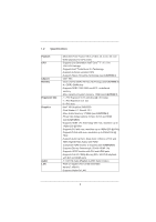
CPU Chipset Memory Expansion Slot Graphics Audio LAN - Micro ATX Form Factor: 9.6-in x 9.6-in, 24.4 cm x 24.4 cm - Solid Capacitor for CPU power - Supports 2nd Generation Intel® CoreTM i7 / i5 / i3 in LGA1155 Package - Supports Intel® Turbo Boost 2.0 Technology - Supports K-Series unlocked CPU - ASRock H61M-GE | User Manual - Page 7
32Mb AMI BIOS - AMI UEFI Legal BIOS with GUI support - Supports "Plug and Play" - ACPI 1.1 Compliance Wake Up Events - Supports jumperfree - SMBIOS 2.3.1 Support - IGPU, DRAM, PCH, CPU PLL, VTT, VCCSA Voltage Multi-adjustment - Drivers, Utilities, AntiVirus Software (Trial Version), ASRock Software - ASRock H61M-GE | User Manual - Page 8
16) * For detailed product information, please visit our website: http://www.asrock.com WARNING Please realize that there is a certain risk involved with overclocking, including adjusting the setting in the BIOS, applying Untied Overclocking Technology, or using the third-party overclocking tools - ASRock H61M-GE | User Manual - Page 9
the setting of "Hyper Threading Technology", please check page 42. 2. This motherboard supports Dual Channel Memory Technology. Before you implement Dual Channel Memory Technology, make sure to read the installation guide of memory modules on page 19 for proper installation. 3. Due to the operating - ASRock H61M-GE | User Manual - Page 10
40% faster than before. ASRock APP Charger allows you to quickly charge many Apple devices simultaneously and even supports continuous charging when your PC enters into Standby mode (S1), Suspend to RAM (S3), hibernation mode (S4) or power off (S5). With APP Charger driver installed, you can easily - ASRock H61M-GE | User Manual - Page 11
to adopt three different CPU cooler types, Socket LGA 775, LGA 1155 and LGA 1156. Please be noticed that not all the 775 and 1156 CPU Fan can be used To meet EuP standard, an EuP ready motherboard and an EuP ready power supply are required. According to Intel's suggestion, the EuP ready power supply - ASRock H61M-GE | User Manual - Page 12
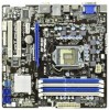
FRONT Bottom: Optical SPDIF DX10.1 Top: Center: Bottom: MIC IN H61M-GE LAN PHY 27 PCIE1 PCI Express 2.0 26 CMOS PCIE2 Battery Super I/O PCI1 Intel 8 H61 9 25 ErP/EuP Ready RoHS AUDIO CODEC HD_AUDIO1 HDMI_SPDIF_1 1 1 1 PCI2 COM1 1 LPT1 IR1 CLRCMOS1 1 1 PLED PWRBTN - ASRock H61M-GE | User Manual - Page 13
Data Activity Orange 100Mbps connection On Link Green 1Gbps connection LAN Port ** If you use 2-channel speaker, please connect details in accordance with the type of speaker you use. TABLE for Audio Output Connection Audio Output Channels Front Speaker Rear Speaker Central / Bass Line In or - ASRock H61M-GE | User Manual - Page 14
To enable Multi-Streaming function, you need to connect a front panel audio cable to the front panel audio header. After restarting your computer, you will nd "Mixer" tool on your system. Please select "Mixer ToolBox" , click "Enable playback multi-streaming", and click "ok". - ASRock H61M-GE | User Manual - Page 15
This is a Micro ATX form factor (9.6" x 9.6", 24.4 x 24.4 cm) motherboard. Before you install the motherboard, study the con guration of your chassis to ensure that the motherboard ts into it. Make sure to unplug the power cord before installing or removing the motherboard. Failure to do - ASRock H61M-GE | User Manual - Page 16
Intel 1155-Pin CPU, please follow the steps below. Load Plate Load Lever Contact Array Socket Body 1155-Pin Socket Overview Before you insert the 1155-Pin CPU into the socket, please check if the CPU surface is unclean or if there is any bent pin on the socket motherboard for after service. 16 - ASRock H61M-GE | User Manual - Page 17
key Pin1 Pin1 orientation key notch 1155-Pin CPU alignment key 1155-Pin Socket For proper inserting, please ensure to match the two orientation key notches of the CPU with the two alignment keys of the socket. Step 3-3. Carefully place the CPU into the socket by using a purely vertical motion - ASRock H61M-GE | User Manual - Page 18
operation or contact other components. Please be noticed that this motherboard supports Combo Cooler Option (C.C.O.), which provides the exible option to adopt three different CPU cooler types, Socket LGA 775, LGA 1155 and LGA 1156. The white throughholes are for Socket LGA 1155/1156 CPU fan. 18 - ASRock H61M-GE | User Manual - Page 19
run at DDR3 1066 only. 6. Due to chipset limitation, if you plan to install three or four memory modules on this motherboard, please install only single-sided memory modules. 7. This motherboard supports two double-sided or four single-sided DIMMs. Therefore, if you install four DDR3 DIMMs, you can - ASRock H61M-GE | User Manual - Page 20
matches the break on the slot. notch break notch break The DIMM only ts in one correct orientation. It will cause permanent damage to the motherboard and the DIMM if you force the DIMM into the slot at incorrect orientation. Step 3. Firmly insert the DIMM into the slot until the retaining - ASRock H61M-GE | User Manual - Page 21
is used for PCI Express cards with x1 lane width cards, such as Gigabit LAN card, SATA2 card, etc. Installing an expansion card Step 1. Step 2. Step you start the installation. Remove the system unit cover (if your motherboard is already installed in a chassis). Remove the bracket facing the slot - ASRock H61M-GE | User Manual - Page 22
VGA card to this motherboard. This motherboard also provides independent display controllers for DVI-D, D-Sub and HDMI to support dual VGA output so VGA/DVI-D port HDMI port 2. If you have installed onboard VGA driver from our support CD to your system already, you can freely enjoy the bene ts of - ASRock H61M-GE | User Manual - Page 23
than the total capability of the system memory. If you do not adjust the UEFI setup, the default value of "Onboard VGA Share Memory", [Auto], will disable VGA/D-Sub function when the add-on VGA card is inserted to this motherboard. 4. Install the onboard VGA driver and the add-on PCI Express VGA - ASRock H61M-GE | User Manual - Page 24
function is supported on this motherboard. To use HDCP function with this motherboard, you need to adopt the monitor that supports HDCP function as well. Therefore, you can enjoy the superior display quality with high-de nition HDCP encryption contents. Please refer to below instruction for more - ASRock H61M-GE | User Manual - Page 25
23 45 Step3. GND IRTX IRRX ATX+5VSB Install Multi-Angle CIR Receiver to support Hot-Plug function. Please install it before you boot the system. * ASRock Smart Remote is only supported by some of ASRock motherboards. Please refer to ASRock website for the motherboard support list: http://www.asrock - ASRock H61M-GE | User Manual - Page 26
need to clear the CMOS when you just nish updating the BIOS, you must boot up the system rst, and then shut it down before you do the clear-CMOS action. Please be noted that the password, date, time, user default pro le, 1394 GUID and MAC address will be cleared only if - ASRock H61M-GE | User Manual - Page 27
SATAII hard disk or the SATAII connector on this motherboard. Besides six default USB 2.0 ports on the I/O panel, there are two USB 2.0 headers on this motherboard. Each USB 2.0 header can support two USB 2.0 ports. This header supports an optional wireless transmitting and receiving infrared module - ASRock H61M-GE | User Manual - Page 28
(see p.12 No. 16) 1 GND IRTX IRRX ATX+5VSB This header can be used to connect the remote audio devices. 1. High De nition Audio supports Jack Sensing, but the panel wire on the chassis must support HDA to function correctly. Please follow the instruction in our manual and chassis manual - ASRock H61M-GE | User Manual - Page 29
Please connect the fan cables to the fan connectors and match the black wire to the ground pin. CPU Fan Connectors (4-pin CPU_FAN1) (see p.12 No. 1) FAN_SPEED_CONTROL CPU_FAN_SPEED +12V GND 1 2 3 4 Please connect the CPU fan cable to the connector and match the black wire to the ground pin. 29 - ASRock H61M-GE | User Manual - Page 30
fan (Quiet Fan) support, the 3-Pin CPU fan still can work successfully even without the fan speed control function. If you plan to connect the 3-Pin CPU fan to the CPU fan connector on this motherboard, please connect it to Pin 1-3. Pin 1-3 Connected 3-Pin Fan Installation ATX Power Connector (24 - ASRock H61M-GE | User Manual - Page 31
ATAII (SATAII) Hard Disks Installation This motherboard adopts Intel® H61 chipset that supports Serial ATA (SATA) / Serial ATAII (SATAII) hard disks. You may install SATA / SATAII hard disks on this motherboard for internal storage devices. This section will guide you to install the SATA / SATAII - ASRock H61M-GE | User Manual - Page 32
is installed into system properly. The latest SATA / SATAII driver is available on our support website: www.asrock.com 4. Make sure to use the SATA power cable & data cable, which are from our motherboard package. 5. Please follow below instructions step by step to reduce the risk of HDD crash or - ASRock H61M-GE | User Manual - Page 33
the power supply 1x4-pin cable. Connect SATA data cable to the motherboard's SATAII connector. SATA power cable 1x4-pin power connector (White) attention, before you process the Hot Unplug: Please do follow below instruction sequence to process the Hot Unplug, improper procedure will cause the - ASRock H61M-GE | User Manual - Page 34
2.14 Driver Installation Guide To install the drivers to your system, please insert the support CD to your optical drive first. Then, the drivers compatible to your system can be auto-detected and listed on the support CD driver page. Please follow the order from up to bottom side to install those - ASRock H61M-GE | User Manual - Page 35
/ SATAII driver diskette containing the Intel® AHCI driver. After reading the floppy disk, the driver will be presented. Select the driver to install according to the mode you choose and the OS you install. Using SATA / SATAII HDDs without NCQ function STEP 1: Set up UEFI. A. Enter UEFI SETUP UTILITY - ASRock H61M-GE | User Manual - Page 36
UEFI chip on the motherboard stores the UEFI SETUP UTILITY. You may run the UEFI SETUP UTILITY when you start up the computer. Please press or during the Power-On-Self-Test (POST) to enter the UEFI Because the UEFI software is constantly being updated, the following UEFI setup screens - ASRock H61M-GE | User Manual - Page 37
up the selected screen To display the General Help Screen To load optimal default values for all the settings To save changes and exit the UEFI SETUP UTILITY To jump to the Exit Screen or exit the current screen 3.2 Main Screen When you enter the - ASRock H61M-GE | User Manual - Page 38
GPU and motherboard. It should be done at your own risk and expense. CPU Ratio Setting Use this item to change the ratio value of this motherboard. GT hidden if the current CPU does not support Intel SpeedStep technology. Please note that enabling this function may reduce CPU voltage and lead to - ASRock H61M-GE | User Manual - Page 39
Core Current Limit Use this item to add voltage when CPU is in Turbo mode. DRAM Timing Control DRAM Frequency If [Auto] is selected, the motherboard will detect the memory module(s) inserted and assigns appropriate frequency automatically. CAS# Latency (tCL) Use this item to change CAS# Latency (tCL - ASRock H61M-GE | User Manual - Page 40
Use this item to change ODT NOM (CHB) Auto/Manual setting. The default is [Auto]. Voltage Control Power Saving Mode Use this to enable or disable Power Saving Mode. The default value is [Disabled]. CPU Core Voltage Offset Use this to select CPU Core Voltage Offset. The default value is [Auto]. IGPU - ASRock H61M-GE | User Manual - Page 41
wrong values in this section may cause the system to malfunction. ASRock Instant Flash ASRock Instant Flash is a UEFI flash utility embedded in Flash ROM. This convenient UEFI update tool allows you to update system UEFI without entering operating systems rst like MS-DOS or Windows®. Just launch - ASRock H61M-GE | User Manual - Page 42
(C1). The C1 state is supported through the native processor instructions HLT and MWAIT and requires no hardware support from the chipset. In the C1 power state, the processor maintains the context of the system caches. CPU C3 State Support Use this to enable or disable CPU C3 (ACPI C2) report to - ASRock H61M-GE | User Manual - Page 43
provided by Vanderpool Technology. This option will be hidden if the installed CPU does not support Intel Virtualization Technology. No-Excute Memory Protection No-Execution (NX) Memory Protection Technology is an enhancement to the IA-32 Intel Architecture. An IA-32 processor with "No Execute (NX - ASRock H61M-GE | User Manual - Page 44
-d Use this to enable or disable Intel® VT-d technology (Intel® Virtualization Technology for Directed I/O). The motherboard through ef cient memory utilization. In DVMT mode, the graphics driver allocates memory as needed for running graphics applications and is cooperatively using this memory - ASRock H61M-GE | User Manual - Page 45
DVMT Memory You are allowed to adjust the shared memory size in this item. Configuration options: [128MB], [256MB] and [Maximum]. The option [Maximum] only appears when you adopt the memory module with 1024MB or above. 45 - ASRock H61M-GE | User Manual - Page 46
S5]. The default value is [Enabled in S5]. Onboard LAN This allows you to enable or disable the "Onboard LAN" feature. Onboard HD Audio Select [Auto], [Enabled] or [Disabled] for the onboard HD Audio feature. If you select [Auto], the onboard HD Audio will be disabled when PCI Sound Card is plugged - ASRock H61M-GE | User Manual - Page 47
SATA mode. Con guration options: [IDE Mode], [AHCI Mode] and [Disabled]. The default value is [IDE Mode]. AHCI (Advanced Host Controller Interface) supports NCQ and other new features that will improve SATA disk performance but IDE mode does not have these advantages. SATA Controller 0 Please select - ASRock H61M-GE | User Manual - Page 48
3.4.5 Super IO Configuration Serial Port Use this item to enable or disable the onboard serial port. Serial Port Address Use this item to set the address for the onboard serial port. Con guration options: [3F8 / IRQ4] and [3E8 / IRQ4]. CIR Controller Use this item to enable or disable the CIR - ASRock H61M-GE | User Manual - Page 49
3.4.6 ACPI Configuration Suspend to RAM Use this item to select whether to auto-detect or disable the Suspend-toRAM feature. Select [Auto] will enable this feature if the OS supports it. Check Ready Bit Use this item to enable or disable the feature Check Ready Bit. PS/2 Keyboard Power On Use this - ASRock H61M-GE | User Manual - Page 50
this item to enable or disable the use of USB 2.0 controller. Legacy USB Support Use this option to select legacy support for USB devices. There are four con guration options: [Enabled], [Auto], [Disabled] and [UEFI Setup Only]. The default value is [Enabled]. Please refer to below descriptions for - ASRock H61M-GE | User Manual - Page 51
the status of the hardware on your system, including the parameters of the CPU temperature, motherboard temperature, CPU fan speed, chassis fan speed, and the critical voltage. CPU Fan Setting This allows you to set the CPU fan speed. Con guration options: [Full On] and [Automatic Mode]. The default - ASRock H61M-GE | User Manual - Page 52
please select [Enabled]. Con guration options: [Enabled] and [Disabled]. The default value is [Enabled]. Boot From Onboard LAN Use this item to enable or disable the Boot From Onboard LAN feature. Boot Failure Guard Enable or disable the feature of Boot Failure Guard. Boot Failure Guard Count Enable - ASRock H61M-GE | User Manual - Page 53
3.7 Security Screen In this section, you may set or change the supervisor/user password for the system. For the user password, you may also clear it. 53 - ASRock H61M-GE | User Manual - Page 54
this option, it will pop-out the following message, "Save con guration changes and exit setup?" Select [OK] to save the changes and exit the UEFI SETUP UTILITY. Discard Changes and Exit When you select this option, it will pop-out the following message, "Discard changes and exit setup?" Select [OK - ASRock H61M-GE | User Manual - Page 55
install the necessary drivers to activate the devices. 4.2.3 Utilities Menu The Utilities Menu shows the applications software that the motherboard supports. Click on a speci c item then follow the installation wizard to install it. 4.2.4 Contact Information If you need to contact ASRock or want to - ASRock H61M-GE | User Manual - Page 56
on a HDD Larger Than 2TB This motherboard is adopting UEFI BIOS that allows Windows® OS to be UEFI:xxx" to boot. 4. Start Windows® installation. 5. If you install Windows® 7 64-bit OS, OS will be formatted by GPT (GUID Partition Table). Please install the hot x le from Microsoft®: http://support
-
 1
1 -
 2
2 -
 3
3 -
 4
4 -
 5
5 -
 6
6 -
 7
7 -
8
-
9
-
10
-
11
-
12
-
13
-
14
-
15
-
16
-
17
-
18
-
19
-
20
-
21
-
22
-
23
-
24
-
25
-
26
-
27
-
28
-
29
-
30
-
31
-
32
-
33
-
34
-
35
-
36
-
37
-
38
-
39
-
40
-
41
-
42
-
43
-
44
-
45
-
46
-
47
-
48
-
49
-
50
-
51
-
52
-
53
-
54
-
55
-
56
 |
 |

1
H61M-GE
User Manual
Version 1.0
Published February 2011
Copyright©2011 ASRock INC. All rights reserved.